Advertisement
Quick Links
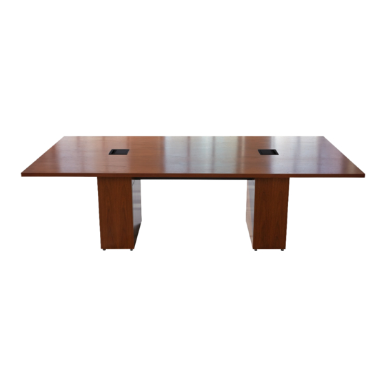
Pre-Select Conference Tables
THANK YOU
Thank you for purchasing a T5 Series Pre-Select Conference Table. Please read these
instructions thoroughly before installing or assembling this product.
PRODUCT FEATURES
• Patent-pending swing-out pedestal rack can be located in the table pedestal of choice.
Innovative flexibility for up to 3 RU of sideways rackmounting, small device mounting or a
combination of the two. Includes three tool-free Lever Lock™ plates for mounting small devices
• Wiremold InteGreat™ Table Boxes in black or silver with 2 retracting HDMI cables and 2 AC
outlets for power and connectivity at the surface. Table boxes and cable retractors are
concealed by the table's pedestal
• Power distribution
• Cable management strips and bridge lances
Instruction Sheet
T5 SERIES
I-00825
Rev -
Advertisement

Subscribe to Our Youtube Channel
Related Manuals for Middle Atlantic Products T5 SERIES


Summary of Contents for Middle Atlantic Products T5 SERIES
- Page 1 T5 SERIES Pre-Select Conference Tables THANK YOU Thank you for purchasing a T5 Series Pre-Select Conference Table. Please read these instructions thoroughly before installing or assembling this product. PRODUCT FEATURES • Patent-pending swing-out pedestal rack can be located in the table pedestal of choice.
- Page 2 IMPORTANT SAFETY INSTRUCTIONS • Read these instructions. • Heed all warnings. • Clean only with dry cloth. • Keep these instructions. • Follow all instructions. • Only use attachments/accessories specified by the manufacturer. DANGER HAZARDOUS VOLTAGE: The lightning flash with the arrowhead symbol, within an equilateral triangle is intended to alert the user to the presence of uninsulated dangerous voltage within the product’s enclosure that may be of sufficient magnitude to constitute a risk of electric shock to persons.
- Page 3 INSTRUCTIONS IMPORTANTES SUR LA SÉCURITÉ • Lire ces instructions. • Respectez tous les avertissements. • Nettoyer uniquement avec un chiffon sec. • Conservez ces instructions. • Suivez toutes les instructions. • N'utilisez que des accessoires spécifiés par le fabricant. DANGER TENSION DANGEREUSE: Le symbole de la pointe de flèche, dans un triangle équilatéral, est destiné à alerter l'utilisateur sur la présence de tension dangereuse non isolée dans l'enceinte du produit qui peut être d'une ampleur suffisante pour constituer un risque d'électrocu- tion.
- Page 4 WEIGHT RATINGS Model Number Weight Rating Tabletop 200 lbs. Maximum Total Rated Load Swing-Out Rack 20 lbs. Maximum Total Rated Load WARNING: This product is intended for use only with the products and maximum weights indicated. Use with other products or products heavier than the maximum weights indicated may result in instability causing possible injury.
- Page 5 SUPPLIED COMPONENTS AND HARDWARE (CONTINUED) SWING-OUT RACK (T5-TECH-KITXX) (20x) #10 x 5/8” Wood (2x) Screw Lacing Strip HDMI Retractors (2x) 10-32 Oval (2x) 10-32 x 1/2” Model Qty. Flat Head Screw 1-Piece Tabletop 2-Piece Tabletop Model Qty. Model Qty. 1-Piece Tabletop 1-Piece Tabletop 2-Piece Tabletop 2-Piece Tabletop...
- Page 6 SUPPLIED COMPONENTS AND HARDWARE (CONTINUED) SWING-OUT RACK (T5-TECH-KITXX) (6x) Lever Lock Securing Rivet Face After Panel A/V Table Box Model Qty. (20x) 1-Piece Tabletop Lever Lock Plate Washer 2-Piece Tabletop FAN OPTION (T5-DCFANKIT-1) (8x) (2x) 10-32 x 3/8” Fan #6 x 3/8” Fan Mounting Screw Fan Controller Controller Mounting...
- Page 7 INSTALLING TROUGHS TO PEDESTAL BASES CAUTION: At least two people are required for pedestal, trough, and tabletop procedures. ATTENTION: Au moins deux personnes sont requises pour les procédures de piédestal, de quille et de table. 1. Before you begin, hand tighten all leveling glides on the pedestal bases as shown. (FIGURE A) TIP: Use 7/16”...
- Page 8 INSTALLING TROUGHS TO PEDESTAL BASES (CONTINUED) 4. Use power driver or screwdriver and (12x for 2-piece tabletop models, 6x for 1-piece models) 1 1/2” wood screws (F) to finish installing the troughs to the pedestal bases as shown. (FIGURE C) NOTE: Use the 1 1/2"...
- Page 9 INSTALLING TROUGHS TO PEDESTAL BASES (CONTINUED) 6. With the assembly now in its final location, use a 4’ level to check across pedestal bases and along troughs and carefully make necessary adjustments by loosening leveling glides as needed. (FIGURE A) INSTALLING THE LACING STRIPS •...
- Page 10 INSTALLING THE HDMI RETRACTORS • Install each HDMI retractor (N) by carefully hooking the shovel lances up and to the center of the retractor bracket as shown. (FIGURE F) NOTE: Carefully push the Shovel Lances retractor inward to secure on Retractors the clip into place.
- Page 11 INSTALLING THE POWER STRIP (CONTINUED) 4. Plug the power cable (U) into the receptacle on the power strip (T) and secure it in place with the Power power cable retainer. (FIGURE H) Cable Retainer 5. Connect the power cable into your desired receptacle.
- Page 12 INSTALLING THE PIVOT BRACKETS 1. Place pivot bracket (V) inside of pedestal with flanges positioned as shown. (FIGURE K) 2. Use power driver and (3x) #10 x 5/8” wood screws (L) to secure the pivot bracket (V) to the side and center of pedestal.
- Page 13 INSTALLING THE FAN OPTION (T5-DCFANKIT-1) 1. Use (4x per fan) 10-32 x 3/8” fan mounting screws (AF) to install each fan (AG) upward into the opening on the pivot bracket (V) with the cables positioned toward the back corners as shown. (FIGURE L) Inside of Pedestal FIGURE L...
- Page 14 INSTALLING THE FAN OPTION (T5-DCFANKIT-1, CONTINUED) 4. Run the cables from each fan to the inline fan controller (AH). (Inputs 1 and 2 are interchangeable.) (FIGURE P) 5. Connect power supply (AK) to input on Jumper Pins inline fan controller (AH). 6.
- Page 15 INSTALLING LEVER LOCK™ INTO THE SWING-OUT RACK (CONTINUED) NOTE: Reposition the rackrails to the second depth position using the (2x, per rail) 10-32 PEM studs and (2x, per rail) 10-32 nuts, if desired. (FIGURE S) 10-32 10-32 PEM Stud FIGURE S 2.
- Page 16 INSTALLING LEVER LOCK INTO THE SWING-OUT RACK (CONTINUED) 3. Use a 10-32 x 3/4” truss screw with washer (Y) to secure the Lever Lock adapter bracket to the rackrail. (FIGURE U) FIGURE U 4. Repeat the process to install the second Lever Lock adapter bracket (X) in the same position as the first, but on the opposite side of the rack.
- Page 17 INSTALLING LEVER LOCK INTO THE SWING-OUT RACK (CONTINUED) 5. Attach the 2” and/or 10” Lever Lock plate (Z and AA, respectively) by installing the side without the clip into the brackets first. Then install the side with the clip until it clicks into place. (FIGURE W) Clip Side with Side without...
- Page 18 INSTALLING THE SWING-OUT RACK NOTE: This topic shows the installation of the swing-out rack in a recommended right swing position inside of the pedestal and may be reversed to have a left swing, if desired. 1. Place the retractable hinge pins into the holes on the pivot bracket (top) and bottom of the pedestal as shown.
- Page 19 INSTALLING THE SWING-OUT RACK (CONTINUED) 2. Use the swing-out rack’s lock pin to secure the rack into the pedestal as shown. (FIGURE AA) FIGURE AA Lock NOTE: When the swing-out rack is installed with a left swing position, the lock pin is on the upper-right side and secures into the pivot bracket (top) instead of the bottom of the pedestal.
- Page 20 ADJUSTING PEDESTAL BASE DOOR (IF NECESSARY) • If necessary, use screwdriver to adjust door hinges as shown. (FIGURE AC) Side Adjustment Height Adjustment Depth Adjustment FIGURE AC JOINING TABLETOP HALVES (2-PIECE TABLETOP MODELS ONLY) CAUTION: At least two people are required for pedestal, trough, and tabletop procedures. ATTENTION: Au moins deux personnes sont requises pour les procédures de piédestal, de quille et de table.
- Page 21 JOINING TABLETOP HALVES (2-PIECE TABLETOP MODELS ONLY, CONTINUED) 2. With tabletops shifted to one end exposing the joint connector holes, insert (4x) joint connectors (J, with hex hole facing downward) and use 5mm hex bit to tighten the seam. (FIGURE AE) Tabletop Seam Joint Connector...
- Page 22 ATTACHING THE BASE ASSEMBLY TO THE TABLETOP(S) (CONTINUED) 2. Use power driver or screwdriver and (12x for 2-piece tabletop models, 8x for 1-piece models) 1” wood screws (G) to attach the pedestal bases to the top as shown. (FIGURE AG) Tabletop Seam CAREFUL: Use the 1"...
- Page 23 ATTACHING THE MENDING PLATES (2-PIECE TABLETOP MODELS ONLY) • Use power driver or screwdriver and (12x) 1" wood screws (G) to attach the 2 mending plates (K) on the bottom of the tabletops (D) as shown. (FIGURE AJ) Tabletop Seam CAREFUL: Use the 1"...
- Page 24 INSTALLING THE TABLE BOXES NOTE: To protect the wood finish from scratching, do not place any parts or tools on the unprotected tabletop surface during assembly. For wood kit care and cleaning, refer to I-00788. • To install the table boxes, refer to the “A/V Table Boxes Installation Instructions” 1011928. (FIGURE AK) NOTE: Position hinge of top lid in the desired direction.
- Page 25 ITE (listée par UL) dans votre table. Tandis que le câblage direct de votre table est possible, il ne doit être effectué que par du personnel qualifié selon NEC, NFPA 70, CEC, CSA C22.1, et tous les codes municipaux locaux. Contactez Middle Atlantic Products pour plus d'informations au (973) 839-1011.
- Page 26 Voice: 613-836-2501 - Fax: 613-836-2690 / ca.middleatlantic.com - customerservicecanada@middleatlantic.ca Factory Distribution USA: NJ - CA - IL Canada: ON - BC At Middle Atlantic Products we are always listening. Your comments are welcome. Middle Atlantic Products is an ISO 9001 and ISO 14001 Registered Company. Page 26...
Need help?
Do you have a question about the T5 SERIES and is the answer not in the manual?
Questions and answers