
Related Manuals for igus Motion Plastics dryve D1


Summary of Contents for igus Motion Plastics dryve D1
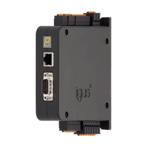
- Page 1 ® igus® Motion Plastics dryve D1, ST- DC- EC/BLDC-Motor Control System Manual V2.4 Website shop Videos/Tutorials www.igus.eu/D1 www.igus.eu/dryve/tutorial 1/121 Operating Manual dryve D1, ST-, DC-, EC/BLDC-Motor Control System - V2.4...
-
Page 2: Table Of Contents
5.4.6 Self-Tuning ..................38 5.4.7 Brake ....................39 5.4.8 Braking Resistor for EC/BLDC Motors ..........40 5.4.8.1 Braking Resistor selection for igus motors ........40 5.4.8.2 Braking Resistor dimensioning for custom motors ......41 5.4.8.3 Braking Voltage Setting ..............44 Axis Configuration ................45 5.5.1 Axis ....................45 5.5.2... - Page 3 Table of contents 5.5.4 Homing .....................49 5.5.5 Analogue Absolute Feedback ............50 Communication ................51 5.6.1 Ethernet TCP/IP ................51 5.6.2 Transmission Protocol ..............52 5.6.3 Bus Systems ..................53 5.6.4 Ethernet MAC address ..............54 Inputs/Outputs ..................55 5.7.1 Digital Inputs ..................55 5.7.2 Digital Outputs ..................58 5.7.3 Digital Outputs Signal Characteristics ..........58 5.7.4...
- Page 4 Table of contents 6.4.13 Cyclic Synchronous Position Mode ..........90 6.4.14 Error ....................90 6.4.15 Object information ................91 6.4.16 Overview of available objects ............91 6.4.17 Detailed description of the objects for motion control .......92 Modbus TCP Gateway ..............102 6.5.1 Necessary User Interface Settings ..........102 6.5.2 Conversion of Integers into Double Word ........103 6.5.3...
-
Page 5: Safety Instructions, Protective Measures And Guidelines
This manual was created according to the best of our knowledge and belief. It is used for technical documentation and for ® assisting the user during the initial operation. The warnings, cautions and instructions issued by igus regarding the dryve D1 motor control system must in any case be passed on to the end user if the dryve D1 motor control system is used as part of an overall system. -
Page 6: Safety Instructions
Safety Instructions, Protective Measures and Guidelines 1.4 Safety Instructions 1.4.1 Information Classification The degree and type of hazard are marked unambiguously. All safety instructions are assigned to one of the following classes. DANGER! Safety instructions marked with DANGER indicate an imminently hazardous situation. A disregard of the notice inevitably leads to a serious or even fatal accident. -
Page 7: Quick Setup
Quick Setup 2 Quick Setup Thank you very much, for choosing the dryve D1 motor control system! In the following, "quick initial operation" it is explained how to setup the dryve D1 and to control a stepper or DC-Motor with a PC. - Page 8 Quick Setup Connect the components in accordance with the following diagrams and instructions. When connecting the cores, take note of the following illustrations, which are intended to assist you. Press the orange spring into the connector by hand or with pliers and hold the spring down.
- Page 9 Quick Setup X5 Motor Connector For a Stepper Motor: Connect inputs X5.1 - X5.4 in accordance with the following diagram. For a DC-Motor: Connect inputs X5.1 and X5.2 in accordance with the following diagram IP address The IP address which is assigned by the PC to the dryve D1 must be entered in the browser in order to establish a connection to the dryve D1.
- Page 10 "quick initial operation" of the system have already been made ex works. Specify the motor type ® Select the igus article number that is shown on the motor label The parameters are set automatically Leave the field by clicking in a free area Click on "Apply"...
- Page 11 Quick Setup Enter the Available Stroke and the Feed Rate. The Feed Rate defines the performed movement with each motor shaft revolution. A possible value for the Available Stroke is for example 100 mm and 60 mm for the Feed Rate. These values must be adopted to the used linear axis.
- Page 12 The program can be stopped with the "Stop" button. If the program were to be started again, it would continue from the marked row. ® For igus motors, the motor controller data have been set appropriately by default. For user-defined motors, the controllers must be parameterised.
-
Page 13: Product Overview
(PC or PLC) via a standard Ethernet cable. The user interface is displayed in a browser of your ® choice, without having to install any additional software. This makes it possible to parameterise the igus dryve D1 motor controller in an extremely short time. -
Page 14: Technical Data
Product Overview 3.2 Technical Data Mechanical Data D x W x H in millimetres, incl. connectors & mounting elements 124 x 31 x 139 Weight in grams 200 g Electrical Data CAUTION! • Risk of destruction An operating voltage above the voltage indicated in the technical data will destroy the dryve D1 Select an operating voltage within the voltage range specified in the technical data. - Page 15 Product Overview Feedback Internal Voltage Source Short Circuit Protected 1 – 4096 increments Resolution Encoder Input Frequency Min. 300 kHz Hall Sensor Input Frequency 5 kHz Holding Brake Voltage output 24 V Current output Max. 1 A PWM at 48 V U at X 1.1 312 kHz Min.
-
Page 16: Installation
Installation Environmental Conditions WARNING! Danger of malfunction Fire hazard Explosion hazard Danger of electric shock Never operate the dryve D1 motor control system in water or in an aggressive, flammable or explosive atmosphere. Ambient Temperature Operation -20 °C to +45 °C Transport -40 °C to +60 °C Storage... -
Page 17: Electrical Installation
Installation 4.2 Electrical Installation WARNING! Danger of electrical voltage Danger of electric arcs Danger of injury and destruction of components. Always turn off the power before disconnecting or making electrical connections in the system. Secure the power supply against restart. After switching the device off, wait at least 5 minutes. -
Page 18: Power Supply Selection
Installation CAUTION ! The connection terminals are designed for single wires. A firm connection cannot be guaranteed due to improper multiple occupancy. There is a risk that wires may slip out of the terminals and cause short circuits. If several signals/wires have to be connected to one terminal, they must be brought together via an external terminal and connected from there with a single wire. - Page 19 Installation The arrow marks pin 1 19/121 Operating Manual dryve D1, ST-, DC-, EC/BLDC-Motor Control System - V2.4...
- Page 20 Installation Connector Assignment Description 12 - 48 V Load Motor Voltage Supply (necessary for operation) Logic/Load-Voltage 0 V Logic/Load Common Ground (necessary for operation) 12 - 24 V Logic Controller Voltage Supply (necessary for operation) Binary Tipp/Teach Step/Direction Digital Input 1 Bit 0 Bit 0 Step...
-
Page 21: Pin Assignment
Installation 4.2.2 Pin Assignment The connectors must be wired according to your application. For this purpose, use the detailed illustrations below for each individual connector. X1 Logic/Load Connector If the dryve D1 is to be connected as a PELV wiring, the 0 V X1.2 terminal is to be connected to the earth potential of the overall application. - Page 22 Installation X4 Analogue Inputs Connector With the Analogue Inputs it is possible to process position and velocity setpoints as well as position feedbacks with a 0 V to 10 V or ± 10 V signal. An analogue position setpoint potential can be supplied by an external master (i.e. a higher-level control system, whereby the external voltage supply must be connected to the X4.4 ground contact) to X4.2 as well as voltage- changing components (e.g.
- Page 23 Installation The following illustrations show how to connect a holding brake to X5.6 and X5.7. If the dryve D1 motor control system is operated with a load voltage of 24 V at X1.1, the voltage is directly passed on to the X5.6 brake output.
- Page 24 Installation X6 Feedback Connector The dryve D1 supports Incremental Feedback (Encoder) and Hall Sensors for position determination with a supply voltage of 5 V. These can be single-ended or line-driver (Encoder) or 2-pole or 3-pole Hall Sensors. If an encoder has an index channel, one homing pulse per motor revolution can be processed. The following table shows the connection assignment.
- Page 25 Installation Stepper Motor EC/BLDC-Motor DC-Motor 25/121 Operating Manual dryve D1, ST-, DC-, EC/BLDC-Motor Control System - V2.4...
-
Page 26: Communication Interfaces
Installation 4.2.3 Communication Interfaces X7 CANopen Port The dryve D1 may be controlled with the CANopen communication protocol. For this purpose, the dryve D1 will be connected to the bus and the master via the CANopen port. The standard pin assignment in accordance with CiA 301 is illustrated in the table. -
Page 27: Initial Operation And User Interface
Initial Operation and User Interface Ethernet To configure the dryve D1, the Ethernet Port must be connected to a network or directly to a computer via a patch cable. Communication is based on the TCP/IP protocol. Modbus TCP Gateway If the communication shall be executed via the Modbus TCP Gateway protocol, the Ethernet Port must be connected to a network or directly to a computer via a patch cable. -
Page 28: Connection Loss
Initial Operation and User Interface 5.1.1 Connection Loss If the Ethernet connection to the dryve D1 is interrupted, the dryve D1 automatically tries to re-establish it. In such a case, a dialogue window displays help topics. Once the connection has been re-established and communication is possible, the dryve D1 automatically reconnects itself to the user interface, the dialogue window closes automatically and the parameterisation can be continued in the same tab. -
Page 29: User Interface Information
Initial Operation and User Interface 5.2 User Interface Information Navigation Menu The desired page will be displayed by clicking on the corresponding tab in the grey navigation menu at the left-hand edge of the screen. The page currently being shown is highlighted in orange. Switches The status of the individual ON/OFF switches and Either-Or switches can be changed by clicking on them. -
Page 30: Entering Parameters
Initial Operation and User Interface 5.2.1 Entering Parameters The parameters entered are transferred directly, i.e. "live", to the control system. Additional confirmation, advance deactivation of the "Enable" signal or a reboot of the control system is only necessary for parameters that are critical for operation. Before the dryve D1 is rebooted, a period of 5 seconds must elapse before altered parameters are permanently saved. -
Page 31: Start
Initial Operation and User Interface 5.3 Start 5.3.1 Language The following languages are available for operation of the dryve D1: German English The user can select a language by clicking on the respective national flag. 5.3.2 Measuring System The user can choose between the metric and imperial measurement systems. -
Page 32: Configuration
Initial Operation and User Interface 5.3.5 Configuration The whole parametrisation, as well as the Drive Profile can be saved and reloaded as a configuration file. Configuration Name Assignment Click in the blank text field and enter the desired configuration name. 40 characters are available. Leave the field by clicking somewhere outside the text field The new Configuration Name is now set and displayed on top of the user interface Save... -
Page 33: Password
Initial Operation and User Interface Update process Deactivate the dryve D1 via disabling the Digital Input 7 “Enable” (external signal or use of the switch on “Inputs/Outputs” page Click on "Update" The file manager of the browser opens automatically Navigate to the storage location of the firmware file (dryve-D1-1-XXXXXXXX.cpio) Select it and click on "Open"... -
Page 34: Motor Configuration
Initial Operation and User Interface 5.4 Motor configuration The dryve D1 can control Stepper, DC and EC/BLDC-Motors. Basic information is provided in the following chart. Stepper Motor (ST) Parameters Description Motor Current Indicates the maximum permissible continuous current of the motor. Boost Current The Boost Current indicates the increase of the Motor Current during acceleration and deceleration phases. -
Page 35: Motor
Initial Operation and User Interface 5.4.1 Motor NOTE A motor type change is only possible after DI 7 "Enable" has been revoked. NOTE The "Auto" mode adapts the Step Mode in relation to the motor's shaft speed. At low rotating speeds, the 1/64 Step Mode is preselected and, when the rotating speed increases, it is successively changed until 1/1 Full Step Mode is reached NOTE The maximum of 25.000 steps/seconds must not be exceeded if a fixed step mode is being used (steps per revolution... -
Page 36: User-Defined Motor
The parameters "Motor Current", "Boost Current", "Holding Current", "Step Angle" and "Pole pairs" are automatically filled with standard values. The predefined igus® motor currents have been reduced by 25% compared to the datasheet values Installed peripheral devices such as motor-mounted gearboxes or feedback systems, including the necessary parameters, are automatically set and activated Motor-specific control parameters are entered automatically on the "Oscilloscope"... -
Page 37: Gear
® If you have selected a "Custom article" at "Article Number" or if you want to use a gearbox that matches an igus motor, please configure the gearbox manually. For this purpose, use the Help information provided in the manual or on the user interface. -
Page 38: Closed-Loop
Initial Operation and User Interface Deactivate the dryve D1 by revoking the DI 7 "Enable" signal (external signal or switch on the "Inputs/Outputs" page) Activate a “Feedback” by setting the switch to "ON" Select the used Feedback from the dropdown menu 10. -
Page 39: Brake
If a holding brake is mounted but not activated, malfunctions or component damage can occur NOTE ® The igus motors with built-in brakes are designed as holding brakes. These brakes are only designed for holding the load in position at a standstill and are not used to decelerate loads during a movement. -
Page 40: Braking Resistor For Ec/Bldc Motors
NOTE The Braking Resistor is only available for EC/BLDC motors. 5.4.8.1 Braking Resistor selection for igus motors The stated resistor values were determined from different application scenarios and are meant as a guideline to select an appropriate resistor. -
Page 41: Braking Resistor Dimensioning For Custom Motors
Initial Operation and User Interface 5.4.8.2 Braking Resistor dimensioning for custom motors The Braking Resistor value and power rating are determined according to the following formulas. NOTE The minimal resistance with 48 V at X1.1 is 1,7 Ω and 0,8 Ω with 24 V. If a lower resistance is used the error E02 “Motor Overcurrent”... - Page 42 Initial Operation and User Interface Power dissipation value Horizontal application �� ���������� �� = �� √ ���������� ∅ nom ���������� 3 ∗ (�� + �� + �� ���������� ���������� ���������� Average motor braking power produced at a single movement cycle in watt [W]] brake Ø...
- Page 43 Initial Operation and User Interface Vertical application: �� �������� �������� �� �� ���������� ( √ ���������� + √ 3 ∗ (�� + �� + �� 3 ∗ (�� + �� + �� ���������� ���������� ���������� ���������� ���������� ���������� �� = �� ����������...
-
Page 44: Braking Voltage Setting
Initial Operation and User Interface 5.4.8.3 Braking Voltage Setting GEFAHR! Fire Hazard! Incorrect Braking Voltage settings can cause a fire hazard! If the Braking Voltage is set below the applied Load Voltage at X1.1, the Braking Resistors power rating is too low and the power supply is not adequately dimensioned an „Overload protection shut off“... -
Page 45: Axis Configuration
Initial Operation and User Interface 5.5 Axis Configuration Available settings for linear or rotational axis configuration are described in the following. 5.5.1 Axis Necessary basic settings for exact positioning. Settings Description Available Stroke Specifying the movement window for "ABS" mode (Absolute Positioning). All other modes remain unaffected by this restriction. - Page 46 Initial Operation and User Interface Setting Description Following Error Permissible deviation of the actual position from the desired position. If 50% of the permissible Following Error is reached, a warning is displayed. If the permissible Following Error is exceeded, the movement is stopped and an error message will be displayed.
-
Page 47: Limit Switch
Initial Operation and User Interface 5.5.3 Limit Switch Specification of the position and number of limit switches used. Setting Description None No limit switch installed on the axis Negative Limit switch placed at the negative end of the axis Positive Limit switch placed at the positive end of the axis Negative and Positive Limit switches placed at the positive and negative ends of the axis... - Page 48 Initial Operation and User Interface Triggered Limit Switches If an activated limit switch is triggered, the "E12 Limit Switch" error is shown and the movement is stopped. A retracting movement in the opposite direction is possible after the error has been acknowledged. If no position feedback is used, a triggered Limit Switch causes the “Referenced”...
-
Page 49: Homing
Initial Operation and User Interface 5.5.4 Homing Selection of the preferred homing method and specification of a position offset. Methods Description SCP Set Current Position Homing takes place at the current position LSN Limit Switch Negative Homing takes place at the negative limit switch LSP Limit Switch Positive Homing takes place at the positive limit switch IEN Index Encoder Negative... -
Page 50: Analogue Absolute Feedback
Initial Operation and User Interface 5.5.5 Analogue Absolute Feedback Configuration of the analogue Target Position value and the analogue Current Position value. Available Stroke (p. 45) will be integrated with these voltages. Example: If the Available Stroke is set to 100 mm and the set voltage interval at Analogue Input AI 1 is from 1 V up to 9 V, these 100 mm will be mapped on the available 8 V (100 mm / 8V = 12,5 mm per 1 V at Analogue Input AI 1). -
Page 51: Communication
Initial Operation and User Interface 5.6 Communication Configuration of the different communication forms with a web browser and higher-level automation controllers. 5.6.1 Ethernet TCP/IP Configuration of Ethernet TCP/IP communication. The IP address can be assigned automatically or manually. The following methods are available for automatic assignment of the IP address. •... -
Page 52: Transmission Protocol
Initial Operation and User Interface Preferred IP Address Assignment Method Selection Select "Automatic IP" or "Manual IP" In the case of "Automatic IP", no further settings must be made Please go straight to point 6 Entry of the desired "IP Address" Entry of the desired "Subnet Mask"... -
Page 53: Bus Systems
Initial Operation and User Interface Selection of the preferred Transmission Protocol Select "HTTPS" or "HTTP" If you choose "HTTP", no further settings must be made Please go straight to point 3 Selection of the certificate type "Self-signed HTTPS certificate" Click on "Generate" External “HTTPS”... -
Page 54: Ethernet Mac Address
Initial Operation and User Interface Activation of CANopen communication Enter the "Node ID" intended for the dryve D1 in the text field Select the Node transmission rate from the dropdown menu Activate CANopen communication with the switch After activation, it is possible to send and receive CANopen data to and from the dryve D1. Movement commands, however, cannot be processed until dominance has been set on the "Drive Profiles (p.56)"... -
Page 55: Inputs/Outputs
Initial Operation and User Interface 5.7 Inputs/Outputs The digital inputs and outputs respectively receive and send signals for communication purposes "High" signals (H) or "Low" signals (L). 5.7.1 Digital Inputs Signals under 10% of the voltage applied at X2.11 are evaluated as "Low". Signal over 60% as "High" Input level percentage DI to voltage at X2.11 100% High... - Page 56 Initial Operation and User Interface Binary Input Function Description DI 1 Bit 0 Bit for binary coding DI 2 Bit 1 Bit for binary coding DI 3 Bit 2 Bit for binary coding DI 4 Bit 3 Bit for binary coding DI 5 Bit 4 Bit for binary coding...
- Page 57 Initial Operation and User Interface Input Function Description DI 1 Bit 0 Bit for binary coding DI 2 Bit 1 Bit for binary coding DI 3 Bit 2 Bit for binary coding DI 4 Jog Left Negative traversing with jog velocity DI 5 Jog Right Positive traversing with jog velocity...
-
Page 58: Digital Outputs
Initial Operation and User Interface 5.7.2 Digital Outputs The dryve D1 outputs status messages via the five Digital Outputs. These can be evaluated by a master control unit (PLC, etc.) or can be used for information display via an external signal hardware. - Page 59 Initial Operation and User Interface Example: I/O Movement with Error Signal Type Signal Typ Bereit Aktiv Referenziert Alert Error internal Ziel erreicht DI / internal Freigabe Example: I/O Movement with Feedback Error Signal Type Signal Typ Bereit Aktiv Referenziert Alert Error internal Ziel erreicht...
-
Page 60: Analogue Inputs
Initial Operation and User Interface Example: Bus operation with Closed Loop and active Positioning Window Signal Type Signal Typ Ready Active Referenced DO/CAN Alert Error CAN/Internal Goal Reached DI / internal Enable 5.7.4 Analogue Inputs 0 V to 10 V and ± 10 V signals can be converted into setpoints and position feedback via the analogue inputs. Setting Operating Mode AI 1... -
Page 61: Drive Profile
Initial Operation and User Interface 5.8 Drive Profile 5.8.1 Drive Mode Selection The selection will set the corresponding drive mode dominant and is now entitled to execute movements. Available for selection are: • „Binary“ – Use of the digital in/outputs to preselect motion profile •... -
Page 62: Test Function
Initial Operation and User Interface 5.8.2 Test Function Created commands can be tested with the help of the "Start", "Stop" and "Quick-Stop" buttons. Select the "Inputs/Output" tab in the Navigation menu Set DI 7 “Enable Select the "Drive Profile" tab in the Navigation menu Mark the row to be executed by clicking in the number field in front of it Click on "Start"... -
Page 63: Binary
Initial Operation and User Interface 5.8.4 Binary The following parameters are set on the page Drive Profile (p. 62). Delays specified at "Pause" are not started until the positioning movement has ended. The row link "Next" is executed when the pause time is lapsed. - Page 64 Initial Operation and User Interface Mode Description Analogue Rotation with Direction Definition Rotary movement with a set acceleration and maximum velocity. The rotation direction and the rotation velocity setpoint is set via Analogue Input "AI 1". The signal can be supplied manually or by a higher-level control system.
- Page 65 Initial Operation and User Interface In the following chapter the configuration steps for each mode are explained. Select "HOM" in the “Mode” drop-down menu. If "SCP" has been selected as homing type on the "Axis" page, go straight to point 4 The "Position"...
- Page 66 Initial Operation and User Interface Select "ARO" in the “Mode” drop-down menu Select the desired motor rotation direction at “Position” Enter the desired values for "Acceleration" and "Deceleration". If no value or a 0 (zero) is entered at "Deceleration", the value from "Acceleration" is used The final setup of the “ARO”...
-
Page 67: Tipp/Teach
Initial Operation and User Interface 5.8.5 Tipp/Teach The following parameters are set on the page Drive Profile (p. 62). Execution of the created motion sequences is explained under Signal Exchange, Tipp/Teach (p.72). The following command modes are available in the "Binary" operating modes Mode Description Homing run... -
Page 68: Oscilloscope And Controller Data
Initial Operation and User Interface 5.9 Oscilloscope and Controller Data 5.9.1 Oscilloscope Settings The internal oscilloscope enables simultaneous observation of 4 channels over a period of 5 seconds. Each channel can transfer one of eight different values. • Actual current (A) •... -
Page 69: Controller Data
D1 to the requirements of very different applications. ® For igus motors, universal parameters have already been set. In applications with high velocities or with heavy loads or special attention to noise minimisation , it might be necessary to fine-tune the Control Data settings. -
Page 70: Controller Data Fine-Tuning
Initial Operation and User Interface 5.9.3 Controller Data Fine-Tuning ® If you want to manually parameterise motors not supplied by igus , observe the following instructions. CAUTION! A current controller with incorrect settings may damage the dryve D1 or the connected motor! -
Page 71: Feed Rate Specification
Initial Operation and User Interface 5.10 Feed Rate Specification If the “Feed rate” is not known, It can be easily determined with a measuring instrument such as a steel ruler. This procedure is described with reference to an example. NOTE Do not carry out a homing run before specifying the feed rate. - Page 72 Initial Operation and User Interface If the carriage moves very slowly or hardly at all, gradually increase the “Jog Velocity” on the "Axis" page, until a movement is clearly visible. If the carriage moves too quickly, reduce the “Jog Velocity” 25.
-
Page 73: Absolute Feedback
Initial Operation and User Interface 5.11 Absolute Feedback Analogue Setpoints Configuration (APS, ARO, ADR) Enter the voltage for the minimum stroke in "AI 1 Stroke Min". Enter the voltage for maximum stroke in "AI 1 Stroke Max". Absolute Feedback Configuration Activate the “Feedback”... -
Page 74: Impulse Check With Physical Limitation
Reset to factory settings, incl. deletion of all entered parameters ® Pierce the product label on the right-hand side of the left-hand "u" arc of the igus logo Insert a long thin object, e.g. a straightened paper clip, into the opening... -
Page 75: External Signal Exchange
External Signal Exchange 6 External Signal Exchange 6.1 Binary Positioning movements created with the Drive Profile (p.56) can be started as well from a higher-level control system. The Digital In/Outputs are used for communication. Certain requirements must be complied before parameterised positioning movements are executed. These requirements depend on the chosen mode. -
Page 76: Binary Signal Sequence
External Signal Exchange ABS, APS Set Di 7 “Enable” "Ready" signal at DO 1 No "Active" signal at DO 2 "Referenced" signal at DO 3 No "Error" signal at DO 5 “Available Stroke” “Feed Rate” “Max. Velocity” “Jog Velocity” (≤”Max. Velocity”) 10. - Page 77 External Signal Exchange Summary Binary Movement Selection The table shows which Digital Inputs must be switched to select the desired positioning movement. If you use the Inverting function (switch for the respective input changed from "H" (High) to "L" (Low) on the "Inputs/Outputs" page), this input will be interpreted as active if it is pulled to ground.
-
Page 78: Tipp/Teach
External Signal Exchange 6.2 Tipp/Teach Besides manual positioning, parameterised positioning movements as created under Drive Profile (p.56) can be executed by a higher-level control system (p.96f) as well. The Digital In/Outputs are used for communication. Certain requirements must be complied before parameterised positioning movements are executed. These requirements depend on the chosen mode. -
Page 79: Tipp/Teach Signal Sequence
External Signal Exchange “HOM” Requirements for a “Homing” execution: Set Di 7 “Enable” "Ready" signal at DO 1 No "Active" signal at DO 2 No "Error" signal at DO 5 “Available Stroke” “Feed Rate” “Max. Velocity” “Jog Velocity” (≤”Max. Velocity”) “Max, Acceleration”... - Page 80 External Signal Exchange The table shows which Digital Inputs must be switched to select the desired positioning movement . If you use the Inverting function (switch for the respective input changed from "H" (High) to "L" (Low) on the "Inputs/Outputs" page), this input will be interpreted as active if it is pulled to ground.
-
Page 81: Step/Direction
External Signal Exchange 6.3 Step/Direction Each positive edge of a square wave signal corresponds to a step movement. The acceleration and velocity is varied with the applied signal frequency. The amount of counted positive edges determines the goal position. NOTE Step/Direction mode is momentarily available for Stepper Motors only. -
Page 82: Canopen
External Signal Exchange 6.4 CANopen In the following chapter, the CANopen interface is explained. The implementation is according to CiA301 and CiA402 (CiA402-3 servo drives) 6.4.1 Special Features of SDO/PDO Communication SDO communication is primarily for parameterisation of object entries. If the dryve D1 is disconnected from the voltage supply, all the configured SDO parameters are lost. -
Page 83: Network Management
External Signal Exchange 6.4.4 Network management An initialisation process must be completed before the dryve D1 can be controlled by the master. This initialisation process is performed by the D1 automatically. Available are SDO and the synchronous and asynchronous PDO data transmission. The asynchronous data transmission is available with and without event timer. -
Page 84: Necessary User Interface Settings
External Signal Exchange Command Bit assignment, Controlword 6040h Transitions Bit 7 Bit 3 Bit 2 Bit 1 Bit 0 Shutdown 2, 6, 8 Switch On Switch On and Enable Operation1 3, 4 Disable Voltage 7, 9, 10, 12 Quick Stop 7, 10, 11 Disable Operation Enable Operation... -
Page 85: State Machine Visualisation
External Signal Exchange 6.4.6 State Machine Visualisation Start D1 boot up Not ready to switch on Automatic state transition Read Statusword 6041h Switch on 0000 0100 0100 0000 (MSB...LSB) disabled 04 64 04 40 Set Digital Input 7 Set Digital Input 7 to status high Read Statusword 6041h Bit 9 = High? -
Page 86: Statusword
External Signal Exchange 6.4.7 Statusword The Statusword provides general operating state information of the dryve D1. Bit assignment of Statusword 6041h Description Different meaning "Mode Specific" Homing Profile Position Profile Velocity Ready to Switch On Switched On Operation Enabled Fault Voltage Enable Quick Stop Switch On Disabled... -
Page 87: Controlword
External Signal Exchange 6.4.8 Controlword The Controlword can be used to trigger changes to the dryve D1 Bit assignment Controlword 6040h Description Different meaning "Mode Specific" Homing Profile Position Profile Velocity Switch On Enable Voltage Quick Stop Enable Operation Mode Specific 0: Homing Blocked 0: No Start Signal 1: Homing Start... -
Page 88: Homing
External Signal Exchange 6.4.10 Homing Homing is used to reach a homing (reference) point and thus specify the zero point of the axis. For this mode to be used, the value 6 must be entered in object 6060h "Modes of Operation". Homing Execution Requirements •... -
Page 89: Profile Position Mode
External Signal Exchange 6.4.11 Profile Position Mode The Profile Position Mode (PP) is used for the execution of positioning movements. To perform positioning movements, the parameters for position, velocity, acceleration and deceleration must be entered. The value 1 must be set in object 6060h "Modes of Operation" so that this mode can be used. Positioning movement Execution Requirements •... -
Page 90: Cyclic Synchronous Position Mode
External Signal Exchange 6.4.13 Cyclic Synchronous Position Mode The Cyclic Synchronous Position Mode (CSP) is used to implement motion control by specifying many individual position points. This mode is particularly suitable for circular movements or for a synchronization of several axes. Accelerations and velocities are generated internally according to the next Target Position command. -
Page 91: Object Information
External Signal Exchange 6.4.15 Object information Variable Information in an object without sub index structures Array Information indicated in an object with sub index structures Visible String Information indicated in an object in the ASCII format. Indication of the length always in sub index 0, information from sub index 1 onwards Unsigned 8 to 32 Type of data for integral values with 8 to 32 bits in the positive value range Integer 8 to 32... -
Page 92: Detailed Description Of The Objects For Motion Control
External Signal Exchange 6.4.17 Detailed description of the objects for motion control 6040h Controlword Short description Object for controlling the dryve D1 Parameter Name Control Word Object Type Date Type UNSIGNED16 0x0006 Access PDO Mapping Bit Assignment Switch On Enable Voltage Quick Stop Enable Operation Mode Specific... - Page 93 External Signal Exchange Example– read “Statusword” CANopen COB-ID Byte0 Byte1 Byte2 Byte3 Byte4 Byte5 Byte6 Byte7 601h Modbus TCP as Gateway Byte 0 - 4 9 - 11 14 - 17 19 - 22 bin 0000 0000 0000 1101 0000 0000 0010 1011 0000 1101 0000 0000 0110 0000 0100 0001 0000 0000...
- Page 94 External Signal Exchange 6067h Position Window Short description Indication of a symmetrical area around the target point. If this area is reached, the target position can be regarded as reached. Parameter Name Position_window Object Type Data Type INTEGER32 0x0004 Access PDO Mapping 6068h Position Window Time Short description...
- Page 95 External Signal Exchange 6081h Profile Velocity Short description Indication of the speed Parameter Name Profile_velocity Object Type Data Type UNSIGNED32 0x0007 Access PDO Mapping 6083h Profile Acceleration Short description Indication of acceleration Parameter Name Profile_acceleration Object Type Data Type UNSIGNED32 0x0007 Access PDO Mapping...
- Page 96 External Signal Exchange Example 3: Positioning movement in the 0,01 mm range, with 5:1 gear Tooth belt axis with 70 mm Feed Rate per motor shaft revolution 6092ℎ: 01 �������� = 70 �� 100 = 7000 6092ℎ: 02 ��ℎ������ ���������������������� = 5 6092ℎ: 01 ��������...
- Page 97 External Signal Exchange 6098h Homing Method Short description Stipulation of the homing method Parameter Name Homing_method Object Type Data Type INTEGER8 0x0002 Access PDO Mapping Value assignment LSN Limit Switch Negative LSP Limit Switch Positive IEN Index Encoder Negative IEP Index Encoder Positive SCP Set Current Position AAF Analogue Absolute Feedback The homing method is set in the user interface.
- Page 98 External Signal Exchange 60C2h Interpolation Time Period Short description Defining the cycle time when a new position increment will be adopted in object 607Ah „Target Position“ If sub-index 01 is set to 5 and sub-index 02 to -3, a position increment will be adopted each 5 ms. −Subindex 02 ����������...
- Page 99 External Signal Exchange Bit assignment of 60DEh sub1 Digital Inputs Bit 16 to 31 DI 1 off DI 1 on DI 2 off DI 2 on DI 3 off DI 3 on DI 4 off DI 4 on DI 5 off DI 5 on DI 6 off DI 6 on...
- Page 100 External Signal Exchange Bit Assignment 60FEh Digital Outputs Brake off Brake on Reserved Reserved Reserved Reserved Reserved Reserved Reserved Reserved Reserved Reserved Reserved Reserved Reserved Reserved Reserved DO 1 off DO 1 on DO 2 off DO 2 on DO 3 off DO 3 on DO 4 off DO 4 on...
- Page 101 External Signal Exchange 6502h Supported Drive Modes Short description Indication of the travel modes supported by the dryve D1 Parameter Name Supported_drive_modes Object Type Data Type UNSIGNED32 0x0007 Access PDO Mapping Bit Assignment Profile Position Mode Velocity Mode Profile Velocity Mode Profile Torque Mode Reserved Homing Mode...
-
Page 102: Modbus Tcp Gateway
External Signal Exchange 6.5 Modbus TCP Gateway The Modbus TCP Gateway communication is implemented as a gateway and is solely used for data telegram transmissions. It is based on the CAN in Automation (CiA) specification "Access from other networks" part 1 " General principles and services" and part 2 "Modbus/TCP mapping“. -
Page 103: Conversion Of Integers Into Double Word
External Signal Exchange 6.5.2 Conversion Decimal into Double Word Decimal Integer Binary Integer as double word Byte 22 Byte 21 Byte 20 Byte 19 0000.0000.0000.0000.0000.0000.0110.0100 0000.0000.0000.0000.0000.0000.1111.1111 0000.0000.0000.0000.0000.0001.0000.0000 2.000 0000.0000.0000.0000.0000.0111.1101.0000 6.000 0000.0000.0000.0000.0001.0111.0111.0000 30.000 0000.0000.0000.0000.0111.0101.0011.0000 150.000 0000.0000.0000.0010.0100.1001.1111.0000 101.253.137 0000.0110.0000.1001.0000.0000.0001.0001 -100 1111.1111.1111.1111.1111.1111.1001.1100 -255 1111.1111.1111.1111.1111.1111.0000.0001 -256 1111.1111.1111.1111.1111.1111.0000.0000... -
Page 104: Byte Assignment Modbus Tcp Gateway Telegram
External Signal Exchange 6.5.4 Byte Assignment Modbus TCP Gateway Telegram Byte Endianness Field Value Description Byte 0 Big Endian Transaction Identification of Modbus telegram (allocation of a response Identifier to a command telegram). The master will set a value, e.g. 1, in the command telegram. -
Page 105: Rx/Tx Telegram Example
External Signal Exchange 6.5.5 RX/TX Telegram Example The following examples show how Ethernet telegrams must be structured to ensure proper communication between the dryve D1 and a Modbus TCP Gateway Master. Listed below are read/write telegrams with the respective response telegram from the dryve D1. The Bytes highlighted in green must be configured for the respective purpose (e.g. reading the Statusword 6041 or writing the Controlword 6040h). - Page 106 External Signal Exchange Byte Telegram Type Task/Information Send Telegram (TX) bin 0000 0000 0000 0000 0000 0000 0000 0000 0000 0000 0000 1101 0000 0000 0010 1011 0000 1101 0000 0000 0000 0000 0000 0000 0110 0000 0100 0001 0000 0000 0000 0000 0000 0000 0000 0000 0000 0010 not send not send not send not send Read Status Request hex 0h...
- Page 107 External Signal Exchange Byte Telegram Type Task/Information Send Telegram (TX) bin 0000 0000 0000 0000 0000 0000 0000 0000 0000 0000 0000 1110 0000 0000 0010 1011 0000 1101 0000 0001 0000 0000 0000 0000 0110 0000 1001 0010 0000 0010 0000 0000 0000 0000 0000 0000 0000 0001 0000 0001 not send not send not send Write Value: Write hex 0h...
- Page 108 External Signal Exchange Byte Telegram Type Task/Information Profile Position Mode Send Telegram (TX) bin 0000 0000 0000 0000 0000 0000 0000 0000 0000 0000 0000 1110 0000 0000 0010 1011 0000 1101 0000 0001 0000 0000 0000 0000 0110 0000 0110 0000 0000 0000 0000 0000 0000 0000 0000 0000 0000 0001 0000 1110 not send not send not send Write Value: Write hex 0h...
- Page 109 External Signal Exchange Byte Telegram Type Task/Information Send Telegram (TX) bin 0000 0000 0000 0000 0000 0000 0000 0000 0000 0000 0000 1110 0000 0000 0010 1011 0000 1101 0000 0001 0000 0000 0000 0000 0110 0000 0110 0000 0000 0000 0000 0000 0000 0000 0000 0000 0000 0001 0000 1111 not send not send not send Command: Write hex 0h...
-
Page 110: Exception Codes Modbus Tcp Gateway
External Signal Exchange 6.5.6 Exception Codes Modbus TCP Gateway In the case of an error the value 80h will be always added to Byte 7. Example Value Byte 7: 2Bh + 80h = ABh (43 + 128 = 171) The value of Byte 7 resend by the dryve D1 is therefore ABh (171). The error information is sent in Byte 8. -
Page 111: Alerts And Errors
Alerts and Errors 7 Alerts and Errors Alerts Description A10 Temperature too high The temperature of the power unit has risen above 85 °C. In the event of a further temperature rise, please increase the cooling air flow, lower the ambient temperature, reduce the acceleration or velocity or insert pauses between the movements. - Page 112 Alerts and Errors Description E08 Load Supply Low No or too little voltage at terminal X1:1-2 Please check if a permissible voltage from 5 to 24 V is applied to the terminal E09 Load Supply High Voltage at terminal X1:1-2 too high Please check if a permissible voltage from 5 to 24 V is applied to the terminal E10 Temperature Power unit is overheated...
-
Page 113: Troubleshooting
Troubleshooting 8 Troubleshooting Temperature Error E10 Description Possible Cause Possible Countermeasures • After a certain operating time, the The power electronic is thermally Load reduction dryve D1 enters the "Stop" state and overloaded due to excessively • Motor Current reduction emits the error "E10 Temperature"... -
Page 114: Faqs
How do I connect a limit switch? The following applies to the igus limit switches: The brown wire is connected to 24V and the blue wire to 0V. Depending on the position, the black wire is connected to terminal X2.8 or X2.9 of the dryve D1. The supply voltage (brown and blue wire of the limit switch) is not provided by the D1. -
Page 115: Accessories
Brake Resistor for Nema 24 BLDC Motors, 100 W, 3,3 Ω DLE-BR-100-3R3 Brake Resistor for Nema 34 BLDC Motors, 100 W, 2,7 Ω DLE-BR-100-2R7 Additional accessories as well as motors available at http://www.igus.eu/drylinE 115/121 Operating Manual dryve D1, ST-, DC-, EC/BLDC-Motor Control System - V2.4... -
Page 116: Abbreviations
Explanation of terminology 11 Abbreviations • Analogue Input • Absolute Positioning in relation to the zero point • Rotational speed with direction set by an external analogue setpoint • Positioning with an external set analogue setpoint • Rotational velocity with an external set analogue setpoint •... - Page 117 Explanation of terminology • DC-Motor A DC-Motor consists of a stator (fixed part) and the rotor (moving part). Pole reversal of the magnetic field is necessary for rotary movement and is executed by the commutator on the rotor. Carbon brushes conduct the electric current through the commutator in a changing flow direction into the motor windings fitted on the rotor.
-
Page 118: Overview Of Input Values
Overview of input values 13 Overview of input values Page Group Subitem 1 Subitem 2 Evaluated input Start Configuration 40 characters Password Admin Change Min. 30 characters Observer Change Min. 30 characters Motor Motor Motor Current All motors 0 A to 7 A Boost Current Stepper Motor Min. - Page 119 Overview of input values Page Group Subitem 1 Subitem 2 Evaluated input Axis Absolute Feedback AI 1 Min. Target Value (V) -10 V to 10 V AI 1 Max. Target Value (V) -10 V to 10 V AI 1 Dead Band Zero Value From 0 to 1 in 0,001 V steps AI 1 Dead Band Input Signal From 0 to 1 in 0,001 V steps...
- Page 120 Overview of input values Page Group Subitem 1 Subitem 2 Evaluated input Oscilloscope Controller Data Current Amplification (P) from 0 to 10,000 Time constant (I) from 0 to 1,000,000 Speed Amplification (P) from 0 to 10,000 Time constant (I) from 0 to 1,000,000 Position Amplification (P) from 0 to 10,000...
-
Page 121: Service
14 Service Customer service DE-dryve@igus.net +49 (0) 2203-9649-845 ® Technical support for igus dryve motor control systems Videos/Tutorials www.igus.de/dryve/tutorial Videos with tutorials on the range of functions of the dryve D1 and how to set it up for operation ®...
Need help?
Do you have a question about the Motion Plastics dryve D1 and is the answer not in the manual?
Questions and answers