Table of Contents
Advertisement
Quick Links
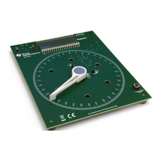
This user's guide describes the characteristics, operation, and use of the
evaluation module (EVM). This EVM demonstrates the application of the
sensor for contactless angle measurement in rotary systems. The EVM implements both encoding and
decoding of absolute angle information. Throughout this document, the terms evaluation board, evaluation
module, and EVM are synonymous with the DRV5055-ANGLE-EVM. This document includes a schematic,
reference printed circuit board (PCB) layouts, and a complete bill of materials (BOM).
SLYU048 – July 2018
Submit Documentation Feedback
Copyright © 2018, Texas Instruments Incorporated
SLYU048 – July 2018
DRV5055-ANGLE-EVM
DRV5055-ANGLE-EVM
DRV5055
DRV5055-ANGLE-EVM
User's Guide
linear Hall effect
1
Advertisement
Table of Contents

Related Manuals for Texas Instruments DRV5055-ANGLE-EVM Series


Summary of Contents for Texas Instruments DRV5055-ANGLE-EVM Series
- Page 1 EVM are synonymous with the DRV5055-ANGLE-EVM. This document includes a schematic, reference printed circuit board (PCB) layouts, and a complete bill of materials (BOM). SLYU048 – July 2018 DRV5055-ANGLE-EVM Submit Documentation Feedback Copyright © 2018, Texas Instruments Incorporated...
-
Page 2: Table Of Contents
List of Tables ....................DRV5055 Device Summary ........................Kit Contents ..................... Related Documentation ......................Bill of Materials Trademarks All trademarks are the property of their respective owners. DRV5055-ANGLE-EVM SLYU048 – July 2018 Submit Documentation Feedback Copyright © 2018, Texas Instruments Incorporated... -
Page 3: Overview
Supports single-sensor configurations for limited-range angle sensing, and dual-sensor configurations for full 360° sensing range • Supports up to 36-point transfer function calibration for < 1° peak-to-peak estimation error • PCB mounting holes SLYU048 – July 2018 DRV5055-ANGLE-EVM Submit Documentation Feedback Copyright © 2018, Texas Instruments Incorporated... -
Page 4: Related Documentation
Newer revisions are available from www.ti.com or the Texas Instruments' Literature Response Center at (800) 477-8924 or the Product Information Center at (972) 644-5580. When ordering, identify the document by both title and literature number. Table 3 lists documentation related to the DRV5055-ANGLE-EVM. -
Page 5: Operation
After calibration is complete, the value displayed on the LCD accurately tracks the position of the pointer. The following sections describe the calibration procedure and available operating modes in greater detail. SLYU048 – July 2018 DRV5055-ANGLE-EVM Submit Documentation Feedback Copyright © 2018, Texas Instruments Incorporated... -
Page 6: Calibration Guide On Bottom Silkscreen For Quick Lookup
For each calibration point that appears on the display, rotate the pointer to the corresponding position on the compass, and press the push-button to store. Figure 2. Calibration Guide on Bottom Silkscreen for Quick Lookup DRV5055-ANGLE-EVM SLYU048 – July 2018 Submit Documentation Feedback Copyright © 2018, Texas Instruments Incorporated... - Page 7 See the Angle Measurements With Linear Hall Effect Sensors Application Report for a detailed discussion of the two measurement modes. SLYU048 – July 2018 DRV5055-ANGLE-EVM Submit Documentation Feedback Copyright © 2018, Texas Instruments Incorporated...
-
Page 8: Hardware
As the magnet rotates, the components of the magnetic flux density vector are measured at points P1 and P2, and are sinusoidal, as shown in the plot of Figure Figure 4. Generating Sinusoidal Magnetic Flux Density Signals DRV5055-ANGLE-EVM SLYU048 – July 2018 Submit Documentation Feedback Copyright © 2018, Texas Instruments Incorporated... - Page 9 (MSPMATHLIB) to efficiently evaluate inverse trigonometric functions. ASIN is used for single-sensor decoding, and ATAN2 is used for dual-sensor decoding. The MSP430 programming interface is also accessible for experimentation. SLYU048 – July 2018 DRV5055-ANGLE-EVM Submit Documentation Feedback Copyright © 2018, Texas Instruments Incorporated...
-
Page 10: Schematics, Pcb Layout, And Bill Of Materials
Version control disabled Assembly Variant: Sheet: warrant that this design will meet the specifications, will be suitable for your application or fit for any particular purpose, or will operate in an im plementation. Texas Instruments and/or its Drawn By: H. Munikoti File: SENS036A_Main.SchDoc... -
Page 11: Top Overlay
PCB Layout NOTE: PCB layout images are not to scale. Figure 6. Top Overlay Figure 8. Bottom Overlay Figure 7. Top Layer Figure 9. Bottom Layer SLYU048 – July 2018 DRV5055-ANGLE-EVM Submit Documentation Feedback Copyright © 2018, Texas Instruments Incorporated... -
Page 12: Bill Of Materials
Hall Effect Sensor Family, DBZ0003A (SOT-23- DBZ0003A DRV5055A3QDBZT Texas Instruments High Accuracy 3.3 V or 5 V Ratiometric Bipolar U2, U4 LPG0003A DRV5055A1QLPGM Texas Instruments Hall Effect Sensor Family, LPG0003A (TO-92-3) DRV5055-ANGLE-EVM SLYU048 – July 2018 Submit Documentation Feedback Copyright © 2018, Texas Instruments Incorporated... - Page 13 PCB Label 0.650 x 0.200 LBL1 THT-14-423-10 Brady inch TP1, TP2, TP3, TP4, TP6, TP7, TP8, TP9, Test Point, Miniature, SMT Test Point, Miniature, SMT 5019 Keystone TP10, TP11, TP12 SLYU048 – July 2018 DRV5055-ANGLE-EVM Submit Documentation Feedback Copyright © 2018, Texas Instruments Incorporated...
- Page 14 STANDARD TERMS FOR EVALUATION MODULES Delivery: TI delivers TI evaluation boards, kits, or modules, including any accompanying demonstration software, components, and/or documentation which may be provided together or separately (collectively, an “EVM” or “EVMs”) to the User (“User”) in accordance with the terms set forth herein.
- Page 15 FCC Interference Statement for Class B EVM devices NOTE: This equipment has been tested and found to comply with the limits for a Class B digital device, pursuant to part 15 of the FCC Rules. These limits are designed to provide reasonable protection against harmful interference in a residential installation.
- Page 16 【無線電波を送信する製品の開発キットをお使いになる際の注意事項】 開発キットの中には技術基準適合証明を受けて いないものがあります。 技術適合証明を受けていないもののご使用に際しては、電波法遵守のため、以下のいずれかの 措置を取っていただく必要がありますのでご注意ください。 1. 電波法施行規則第6条第1項第1号に基づく平成18年3月28日総務省告示第173号で定められた電波暗室等の試験設備でご使用 いただく。 2. 実験局の免許を取得後ご使用いただく。 3. 技術基準適合証明を取得後ご使用いただく。 なお、本製品は、上記の「ご使用にあたっての注意」を譲渡先、移転先に通知しない限り、譲渡、移転できないものとします。 上記を遵守頂けない場合は、電波法の罰則が適用される可能性があることをご留意ください。 日本テキサス・イ ンスツルメンツ株式会社 東京都新宿区西新宿6丁目24番1号 西新宿三井ビル 3.3.3 Notice for EVMs for Power Line Communication: Please see http://www.tij.co.jp/lsds/ti_ja/general/eStore/notice_02.page 電力線搬送波通信についての開発キットをお使いになる際の注意事項については、次のところをご覧ください。http:/ /www.tij.co.jp/lsds/ti_ja/general/eStore/notice_02.page 3.4 European Union 3.4.1 For EVMs subject to EU Directive 2014/30/EU (Electromagnetic Compatibility Directive): This is a class A product intended for use in environments other than domestic environments that are connected to a low-voltage power-supply network that supplies buildings used for domestic purposes.
- Page 17 Notwithstanding the foregoing, any judgment may be enforced in any United States or foreign court, and TI may seek injunctive relief in any United States or foreign court. Mailing Address: Texas Instruments, Post Office Box 655303, Dallas, Texas 75265 Copyright © 2018, Texas Instruments Incorporated...
- Page 18 IMPORTANT NOTICE FOR TI DESIGN INFORMATION AND RESOURCES Texas Instruments Incorporated (‘TI”) technical, application or other design advice, services or information, including, but not limited to, reference designs and materials relating to evaluation modules, (collectively, “TI Resources”) are intended to assist designers who are developing applications that incorporate TI products;...
Need help?
Do you have a question about the DRV5055-ANGLE-EVM Series and is the answer not in the manual?
Questions and answers