Table of Contents
Advertisement
Quick Links
Advertisement
Table of Contents

Subscribe to Our Youtube Channel
Related Manuals for Nauticam NA-5DIV


Summary of Contents for Nauticam NA-5DIV
- Page 2 ORWARD Thank you for your purchase of a NAUTICAM housing. At NAUTICAM, we pride ourselves in the ability to recognise the requirements of professional as well as amateur underwater photographers and fulfill them through the innovative designs of our products. We strive to achieve a high level of user-friendliness by allowing stress-free installation and easy operation of all important functions of the camera.
-
Page 3: Table Of Contents
ABLE OF ONTENTS Warranty ……………………………………………………………………………………………………………. Precautions ………………………………………………………………………………………………………… Package Contents ………………………………………………………………………………………………. Specifications …………………………………………………………………………………………………….. Identification of Parts ………………………………………………………………………………………… Opening and Closing the Housing ……………………………………………………………………… Preparation of the Housing ………………………………………………………………………………… Installing the Camera ………………………………………………………………………………………… Mounting the Port ……………………….……………………………………………………………………. Changing the Viewfinder ……………………………………………………………………..……………. Care and Maintenance ………………………………………………………………………………………. Optional Accessories ………………………………………………………………………………………….. -
Page 4: Warranty
NAUTICAM does not hold responsibility for damage, of any nature, to any equipment used with and/or placed within our products. NAUTICAM accepts no liability for any loss of captured images or the inability to capture images even if it is due to the malfunctioning of our products. -
Page 5: Precautions
O-ring(s). • Do not use lubricants from other brands with the silicone rubber O-ring on this housing, only use the lubricant provided by NAUTICAM. • Discontinue use immediately should you notice any leakage. - Page 6 • Do not open the product in a wet or sandy environment. Protect the interior from moisture and debris in order to prevent malfunction or leakage. • Do not store the product in an environment of high humidity. • Do not leave the housing and the monitor in direct sunlight for prolonged periods. •...
-
Page 7: Package Contents
ACKAGE ONTENTS • NA-5DIV housing • Canon hotshoe plug to dual Nikonos connectors (trigger and ground connections only) • Spare silicone rubber O-ring for housing • O-ring remover • CR2032 battery • Lubricant • Set of Allen keys • Instruction manual... -
Page 8: Specifications
PECIFICATIONS Housing body: Aluminium alloy Construction Surface treatment: Hard anodised Display window: Abrasion resistant polycarbonate Width: 358mm Dimensions Height: 187mm Depth: 135mm Weight Approx. 2.91kg Buoyancy Slightly negative Depth rating 100 metres Port mount N120 Compatible Canon EOS 5D Mark IV camera... -
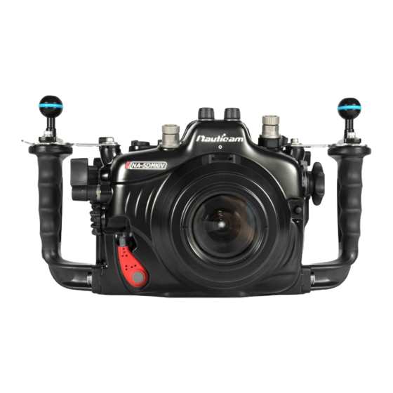
Page 9: Identification Of Parts
DENTIFICATION OF ARTS Optical bulkhead x2 Port alignment index Shutter release lever Handle x2 Port release safety button Port lock/release lever... - Page 10 Mode dial Nikonos 5-pins bulkhead M16 to M14 step On/off lever down adaptor Index/Magnify M5/M10 threaded hole /Reduce lever Zoom/focus gear Playback lever disengagement lever Zoom/focus lever Lens release button...
- Page 11 TTL flash trigger indicator window AE LOCK button Menu button AF point selection button Info button Multi-controller Creative Photo button Quick control button Rating button SET button Housing lock safety button (L) AF area selection button Housing lock Housing lock (L) safety button (R) Erase button Housing lock (R)
- Page 12 White balance/ Metering mode selection button M16 accessory port Nikonos 5-pins bulkhead Drive mode/ AF operation/ On/off button for optional AF method selection button TTL flash trigger PN#26321 M5/M10 threaded hole Live view shooting / M-Fn lever Movie shooting selector Flash compensation/ ISO speed setting lever Start/stop lever...
-
Page 13: Opening And Closing The Housing
PENING AND LOSING THE OUSING To open the housing: Always open and close the housing with the front facing down, place the housing on a flat surface or in your lap. The housing can be opened and closed by operating the two housing locks; when opening, press the safety buttons, then turn the locks outwards. - Page 14 To close the housing: When closing, make sure there is nothing caught between the closing surfaces of the two halves of the housing. To close, turn the locks towards the housing, and then make sure they are locked in place securely.
-
Page 15: Preparation Of The Housing
REPARATION OF THE OUSING 1. After verifying that the main O-ring is in 5. Setting up the moisture alarm: good condition, lightly coat it with the lubricant provided. 2. Make sure the O-ring groove located in the front part of the housing is free from any foreign material;... - Page 16 2. Switch the alarm on. The LED light 3. Test the alarm by connecting the will flash blue once and turn blue two wires near the bottom of the for five seconds indicating the housing with a damp cotton bud; battery is normal.
- Page 17 Optional Vacuum Valve: Vacuum valve can be attached to the housing via one of the accessory port for conducting a vacuum seal test. Please refer to the manual of the vacuum valve for details of the operation. LED status identification: On start up: LED indicator Status...
- Page 18 After start up: LED indicator Status Flashing "Blue" light Standby mode. The moisture alarm is active, and the system is ready for vacuum indication whenever a vacuum is detected. Flashing "Red" light with Moisture is detected. beeping sound Flashing "Yellow" light Some vacuum is detected, target vacuum level is not reached.
- Page 19 To reset when changing port/lens: Release vacuum. Remove the port and lens from the housing and camera. Press the BLUE button once to reset the system. The LED light will turn blue for five seconds then it goes into flashing blue light standby mode.
-
Page 20: Installing The Camera
NSTALLING THE AMERA To install the camera into to the housing: 2. Remove the camera saddle from 1. Turn the locking lever on the tray the housing. of the housing to the “open” position. - Page 21 4. Attach the saddle to the camera 3. Align the pin on the saddle with by tightening the screw to the the opening in the bottom of the tripod socket of the camera with a camera as indicated in the screwdriver or a coin.
- Page 22 Connect 5. Mount the camera by sliding the 6. Lock the camera into place by attached saddle along the rail in turning the locking lever to the the housing until it cannot go in “lock” position. any further. 7. Confirm that all the controls of the housing are correctly engaged.
-
Page 23: Mounting The Port
Connect OUNTING THE Please refer to the NAUTICAM system port chart for a range of compatible ports; note that extension rings may be needed for certain lenses and adaptors are available for the attachment of ports of other manufacturers. To remove housing cap/ port: 2. - Page 24 3. Lift housing cap. 4. Pull down the Zoom/ focus gear disengagement lever before mounting lens (with gears installed) to the camera. Engage the gears by pulling up the lever to the original position. Confirm that zoom/focus knob operates correctly.
- Page 25 To mount port: Remove the O-ring from the port, inspect for any damage and lightly coat it with the provided lubricant before placing it back into its groove. Verify that the port opening of the housing is clean and free from Align the mounting indices of foreign material.
- Page 26 To remove the port from the housing, simply turn the port locking lever to the outward position and gently pull it out. 5. Lock the port into place by turning the port locking lever to the inward position. To ensure that the port is securely mounted, confirm that the green line on the safety button...
-
Page 27: Changing The Viewfinder
HANGING THE IEWFINDER In order that users can change to a preferred viewfinder easily, the 0.66X viewfinder which comes with this housing is designed so that it can be removed and re-installed by following the simple steps described below. To remove the viewfinder: 1. - Page 28 To re-install the viewfinder: 1. Lightly coat the O-rings on the 3. Push the viewfinder from the outside of the housing until it outer periphery of the viewfinder body with lubricant. cannot go in any further. 2. Align the viewfinder with the 4.
-
Page 29: Care And Maintenance
O-ring with the provided lubricant before reinstalling it in the groove. A damaged O-ring should be discarded immediately and replaced only with one that is provided by NAUTICAM. • Replace the main O-ring annually. It is recommended that you ship the housing to our... -
Page 30: Optional Accessories
PTIONAL CCESSORIES P.N. 32201 P.N. 25624 P.N. 32203 M14 Vacuum Valve II Nauticam 180˚ straight Nauticam 45˚ viewfinder viewfinder (Pushbutton Release) P.N. 26321 TTL Flash Trigger for Canon...
Need help?
Do you have a question about the NA-5DIV and is the answer not in the manual?
Questions and answers