
Subscribe to Our Youtube Channel
Related Manuals for Nauticam NA-D800


Summary of Contents for Nauticam NA-D800
- Page 2 Thank you for your purchase of a NAUTICAM digital camera housing. At NAUTICAM, we pride ourselves on the ability to recognise the requirements of professional as well as amateur underwater photographers and fulfill them through the innovative designs of our products. We strive to achieve a high level of user-friendliness by allowing stress-free installation and easy operation of all important functions of the camera.
- Page 3 1. All NAUTICAM Products are warranted against any material and manufacturing defects for one year from the date of purchase for consumer use. 2. NAUTICAM accepts no liability for any damage to and defects in the housing caused by improper use and/or poor maintenance; it is the responsibility of the owner to carefully follow the instructions in this manual.
- Page 4 1. NA-D800 housing 2. Instruction manual 3. Spare silicone rubber main o-ring 4. O-ring remover 5. CR2032 battery (for moisture alarm) 6. Lubricant 7. Set of Allen keys CR2032 battery Spare silicone rubber o-ring O-ring remover Lubricant Set of Allen keys...
- Page 5 O-ring(s). 2. Do not use lubricants from other brands with the silicone rubber O-ring on this housing, only use the lubricant provided by NAUTICAM. 3. Discontinue use immediately should you notice any leakage. 4. Store the housing in a robust, shock-proof container during transportation;...
- Page 6 Specifications Identification of Parts Preparation of the Housing Opening and Closing the Housing Installing the Camera Flash Operation Mounting the Port Connecting the Strobe System Changing the Viewfinder Care and Maintenance...
- Page 7 Housing body: Aluminium alloy Surface treatment: Hard anodised Construction Display window: Abrasion resistant polycarbonate Grip handles: Polycarbonate and rubber Width: 351 mm Dimensions Height: 194 mm (with handles) Depth: 134 mm Weight 2.81 kg (without camera) Buoyancy Slightly negative Depth rating 100 metres Moisture alarm: Blinking LED and audible alarm...
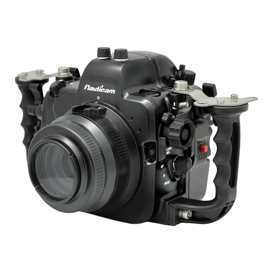
- Page 8 On/Off control knob Movie-record lever Grip handle x 2 AF-ON lever Port lock/release lever Exposure mode button Optical bulkhead for strobe Exposure compensation lever connections x 2 Port alignment index Shutter release lever Metering selector knob Sub-command dial Main command dial...
- Page 9 Delete button Info button Menu button Housing lock (R) Protect/Help button Housing lock safety button (R) Housing lock (L) Live view selector lever Housing lock safety button (L) Multi selector Playback zoom in button Up selection button Thumbnail/Playback zoom out Left selection button button OK button...
- Page 10 M16 optional accessory port AF-mode button Lens release button Image quality/size button Release mode knob White balance button ISO sensitivity lever Bracketing button Playback lever Flash Off lever Flash pop-up/ flash Zoom/ focus gear disengagement compensation button lever Focus mode selection knob Zoom/focus knob...
- Page 11 Shooting Tips 1. By setting the “Release Button to Use Dial” function of the D800 camera to Yes allows adjustments which are normally made by holding down a button and rotating a command dial to be made by rotating the command dial after the button is pressed and released.
- Page 12 2. The length of time that the camera continues to meter exposure can be assigned by the "Auto Meter-off Delay" setting. To control the time period of exposure meters, under Menu, scroll to Custom Setting Menu, enter ‘c’ Timers/AE lock. Then scroll to ‘c2’...
- Page 13 1. After verifying that the main O-ring is in good condition, lightly coat it with the lubricant provided. 2. Make sure the O-ring groove located in the front part of the housing is free from any foreign material; the groove can be cleaned with the aid of a microfiber cloth.
- Page 14 iii. Insert the 5-pin bulkhead through the threaded hole. Tighten the 5-pin bulkhead with a spanner. Connect the 5-pin bulkhead to the accessory shoe plug. Slide the accessory shoe plug of the housing into the accessory shoe of the camera.
- Page 15 Setting up the moisture alarm 1. Install the CR2032 battery provided into the battery compartment on the circuit board inside the rear part of the housing. 2. Test the alarm by contacting the two wires near the bottom of the housing with a damped cotton bud;...
- Page 16 1. Always open and close the housing with the front facing down, place the housing on a flat surface or in your lap. 2. When closing, make sure there is nothing caught between the closing surfaces of the two halves of the housing. 3.
- Page 17 1. Turn the locking lever on the tray 2. Remove the camera saddle from of the housing to the “open” the housing. position. 3. Pull the sliding bar on the saddle 4. Align the pin on the saddle with to its outward position. the opening in the bottom of the camera as indicated in the diagram.
- Page 18 6. After ensuring the C/S/M activator Attach the saddle to the camera on the sliding bar aligns correctly by tightening the screw to the with the focus mode selector of tripod socket of the camera with the camera, push the sliding bar a screwdriver or a coin.
- Page 19 Make sure the Release mode 10. Lock the camera into place by knob is in upwards position turning the locking lever to before aligning the rear the “lock” position. housing with the front housing. Push it down when the housing is closed to gain access to the release mode dial.
- Page 20 The D800 camera’s built-in flash can be used for triggering external strobes. To raise the flash after the camera has been installed into the housing, press the Flash mode/flash compensation button; pressing this button also allows the flash exposure to be adjusted by the sub-command dial.
- Page 21 Please refer to the NAUTICAM port system chart for a range of compatible ports; note that extension rings may be needed for certain lenses and adaptors are available for the attachment of ports of other manufacturers. To remove housing cap: 1.
- Page 22 To mount port: 5. Verify that the port opening of 4. Remove the O-ring from the port, the housing is clean and free from inspect for any damage and foreign material. lightly coat it with the provided lubricant before placing it back into its groove.
- Page 23 Optional strobe attachment balls can be attached to the strobe mounting bases on the housing or onto the top of the handles. There are two ways of connecting strobes to the NA-D800 housing: A) by optical connection through the Optical Bulkheads; B) by electrical connection through the Nikonos 5-pins bulkhead.
- Page 24 Then scroll to ‘e3’ Flash cntrl for built-in flash and enter. Scroll to Commander mode. Set the Built-in flash Mode to ‘--‘, Group A (one of the strobes) to Mode ‘TTL’, and Group B (the other strobe) to Mode ‘TTL’. The exposure compensation of each strobe can be set individually (A and/or B) by entering the value under Comp.
- Page 25 Then scroll to ‘e3’ Flash cntrl for built-in flash and enter. Scroll to TTL and press OK. For Manual operation, set the built-in flash of the D800 camera to Manual mode. From the Menu, scroll to Custom Setting Menu (Pencil shaped icon on the left of the LCD screen), enter ‘e’...
- Page 26 A3) Other strobes The optical signal from the D800 built-in flash can also be utilised to trigger other strobes having an optical sensor. B) Using the Nikonos 5-pin bulkhead The Nikonos 5-pin bulkhead connects to all the 5 contact points of the D800 hotshoe for iTTL compatible operation.
- Page 27 In order that users can change to a preferred viewfinder easily, the 0.66X viewfinder which comes with this housing is designed so that it can be removed and re-installed by following the simple steps described below. To remove the viewfinder: 2.
- Page 28 To re-install the viewfinder: 3. Push the viewfinder from the 1. Lightly coat the O-rings on the outside of the housing until it outer periphery of the cannot go in any further. viewfinder body with lubricant. 4. Place the retainer O-ring of the 2.
- Page 29 O-ring with the provided lubricant before reinstalling it in the groove. A damaged O-ring should be discarded immediately and replaced only with one that is provided by NAUTICAM. 4. Replace the main O-ring annually.
Need help?
Do you have a question about the NA-D800 and is the answer not in the manual?
Questions and answers