Table of Contents
Advertisement
Quick Links
Download this manual
See also:
Manual
Copyright © 2013
All rights reserved.
Publication number: S2153-4980/1
Original instructions: English.
All rights reserved throughout the world. No part of this
document may be stored in a retrieval system, transmitted,
copied or reproduced in any way, including, but not limited
to, photocopy, photograph, magnetic or other record
without the prior agreement and permission in writing of
the Vitec Group plc.
We want you to receive Sachtler products that are always
state of the art. Therefore we reserve the right to make
changes based on technical advances.
Disclaimer
The information contained in this manual is believed to be
correct at the time of printing. Vitec Videocom Ltd reserves
the right to make changes to the information or
specifications without obligation to notify any person of
such revision or changes. Changes will be incorporated in
new versions of the publication.
We are making every effort to ensure that our manuals are
updated on a regular basis to reflect changes to product
specifications and features. Should this manual not contain
information on the core functionality of your product,
please let us know. You may be able to access the latest
revision of this manual from our website.
Vitec Videocom Ltd reserves the right to make changes to
product design and functionality without notification.
Published by:
Vitec Videocom Ltd
Supports Technical Publications Department
William Vinten Building
Western Way
Bury St Edmunds
Suffolk IP33 3TB
United Kingdom
E-mail: technical.publications@vitecgroup.com
Advertisement
Table of Contents

Summary of Contents for Sachtler Ace Follow Focus
- Page 1 Vitec Group plc. We want you to receive Sachtler products that are always state of the art. Therefore we reserve the right to make changes based on technical advances.
-
Page 2: Table Of Contents
Mounting the Ace Follow Focus........ -
Page 3: Safety Instructions
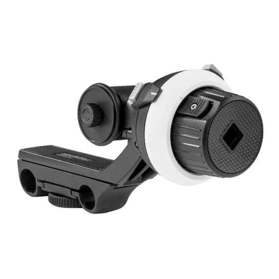
Ø39 mm (1.5 in.) (Min lens dia.) Usage Ø15 mm (0.5 in.) LWS rods The Ace Follow Focus is designed for use by professional camera operators to support Friction wheel high-performance lightweight cameras. The Ace Follow Focus must be mounted onto a Ø35 mm (1.4 in.) -
Page 4: Operating Elements
When the slide switch is disengaged, the handwheel has infinite rotation. The slide switch is located on the handwheel. Marking disc A marking disc is supplied with the Ace Follow Focus to enable the operator to mark focal reference points. The marking disc is fitted over the handwheel. - Page 5 Upper slide bridge When the Ace Follow Focus is mounted on the support rods, the upper slide bridge can be adjusted to accommodate a variety of lens diameters. When the upper slide bridge is in the required position, it is secured in place using the bridge clamp.
-
Page 6: Assembly
Assembling the friction wheel/drive gear The Ace Follow Focus comes supplied with a Ø35 mm friction wheel and a 50 tooth drive gear. The friction wheel/drive gear is secured to either the front or the rear of the double-sided drive. -
Page 7: Rotating The Double-Sided Drive
Rotating the double-sided drive The double-sided drive can be rotated to allow the gear mechanism to move in either direction. To rotate the double-sided drive (see Fig. 4): If fitted, loosen and remove the friction wheel/drive gear that is attached to the shortest side of the double-sided drive [A, B]. -
Page 8: Operation
Operation Mounting the Ace Follow Focus To mount the Ace Follow Focus onto camera rods (see Fig. 5): Ensure that the head platform is level and apply both the horizontal and vertical brakes [A]. If required, rotate the bridge clamp clockwise to loosen the lower support rod bridge [B]. -
Page 9: Setting The Hard Stops
Setting the hard stops Reference points for the maximum and minimum focal distances can be marked on the marking disc. Hard stops allow the operator to set mechanical limits for lenses without them. To set the focal distances (see Fig. 6): Rotate the handwheel to find the start focal point. -
Page 10: Removing The Ace Follow Focus
Removing the Ace Follow Focus To remove the Ace Follow Focus from camera rods (see Fig. 7): Ensure that the head platform is level and apply both the horizontal and vertical brakes [A]. Rotate the bridge clamp clockwise to loosen the lower support rod bridge [B]. -
Page 11: Maintenance
Particular attention should be paid to the lower support rod bridge, the double-sided gear drive spindle and the end stop bezels. The marking disc must be removed from the Ace Follow Focus before cleaning. Follow the instructions supplied with the marking pen when cleaning the marking discs. - Page 12 -11-...


Need help?
Do you have a question about the Ace Follow Focus and is the answer not in the manual?
Questions and answers