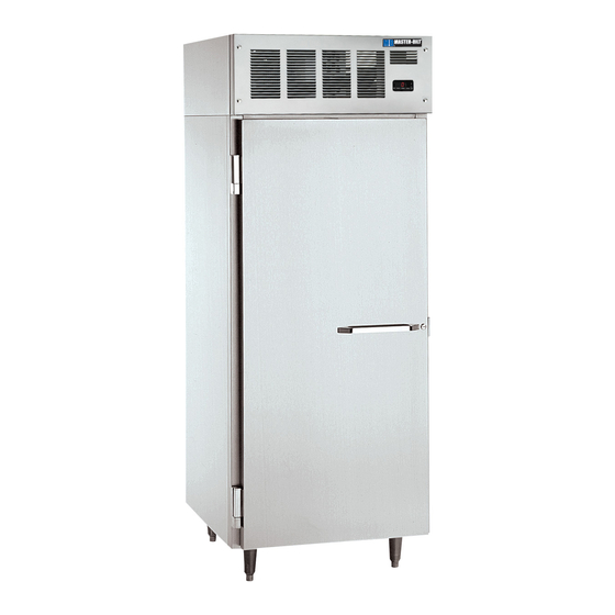
Master Bilt IHC-27 Installation & Operation Manual
Ice cream hardening/holding cabinets
Hide thumbs
Also See for IHC-27:
- Specification sheet (2 pages) ,
- Installation & operation manual (16 pages)

Related Manuals for Master Bilt IHC-27


Summary of Contents for Master Bilt IHC-27
- Page 1 IHC-27 & IHC-48 Ice Cream Hardening/Holding Cabinets Installation & Operations Manual Master-Bilt Products 908 Highway 15 North New Albany, MS 38652 Phone: (800) 684-8988 3/20 Rev. A 57-02699...
-
Page 2: Table Of Contents
Temperature Sensor, Defrost Heater and Fan Motor Replacement…………....……..…………..….8 ELECTRONIC REFRIGERATION CONTROL…………………...…………………………………...………….…….…..9 Operations.................................9 Manual Defrost..............................9 Changing the Set Point............................9 Alarm Signals..............................10 Electrical Connections............................10 FINAL CHECK LIST……………………………………………………..………………………………..…….…………..…10 PART LIST..................................11 ACCESSORIES……………………………………………………………..…………………………….………………..…...11 SALE AND DISPOSAL…..…………………………………………………..………………………………….………..…..11 IHC-27 WIRING DIAGRAM………………..…………………..…………………………..………………….……………..12 IHC-48 WIRING DIAGRAM………………..…………………..…………………………..………………….……………...…13 3/20 Rev. A 57-02699... -
Page 3: Introduction
INTRODUCTION ® Thank you for purchasing a Master-Bilt cabinet. This manual contains important instructions for installing, using, and servicing a ® Master-Bilt IHC case. A parts list is included with this manual. Read all these documents carefully before installing or servicing your equipment. -
Page 4: Warning Labels And Safety Instructions
WARNING LABELS AND SAFETY INSTRUCTIONS DANGER Risk of fire or explosion. Flammable refrigerant used. To be repaired only by trained service personnel. Do not puncture refrigerant tubing. CAUTION Risk of fire or explosion. Flammable refrigerant used. Consult instruction manual/repair manual/owner’s guide before attempting to install or service this product. All safety precautions must be followed. -
Page 5: Pre-Installation Instructions
PRE-INSTALLATION INSTRUCTIONS INSPECTION FOR SHIPPING DAMAGE You are responsible for filing all freight claims with the delivering truck line. Inspect all cartons and crates for damage as soon as they arrive. If damage is noted to shipping crates or cartons or if a shortage is found, note this on the bill of lading (all copies) prior to signing. -
Page 6: Electrical
ELECTRICAL WARNING Before servicing electrical components in the case or the doors or door frames make sure all power to case is off. Always use a qualified technician. Check voltage and amps drawn on (Page 17) to determine proper line and fuse or circuit breaker size. Check power supply for low voltage. -
Page 7: Leg And Condensate Pan Installation
LOW TEMPERATURE FREEZERS – “IHC” Models The power cords are rated 15A, 120 Volt for the IHC-27 and 20A, 120 V for the IHC 48 and are located on top of the cabinet at the right rear for connection to power. On initial start-up the evaporator fan motors will not start and you cannot initiate a defrost until the evaporator coil temperature has lowered to 25F. -
Page 8: Temperature Sensor, Defrost Heater And Fan Motor Replacement
Temperature sensor, drain pan defrost heater, fan motor, drain line heater and temperature probe replacement Before servicing the unit or replacing any components, technician must: Turn the refrigeration rocker switch to the 0 position. This rocker switch is located on top of the cabinet at the back of the control box behind the temperature controller. -
Page 9: Electronic Refrigeration Control
® MASTER-BILT ELECTRONIC REFRIGERATION CONTROL OPERATION Compressor When power is first turned on to the control, the LED indicator under COMP on the display starts blinking. The cabinet will enter a defrost at start-up. The compressor(s) and the Defrost icon will be on. The defrost will last 6 minutes followed by a 3 minutes dripping time. -
Page 10: Alarm Signals
Here is a list of the parameters the value of which can be changed in the programming mode, as well as their ranges. Factory’s Display Setting Description Symbol Temperature set point -25 F Cut-out temperature is Set + Hy, Differential 7... -
Page 11: Part List
MASTER-BILT PART LIST The table below gives Master-Bilt ® part numbers. Use this chart when ordering replacement parts for your IHC cabinets. Always advise cabinet serial number when ordering parts Description IHC-27 IHC-48 Compressor 03-15546 03-15546 Run Capacitor 19-14844 19-14844... -
Page 12: Ihc-27 Wiring Diagram
IHC-27 Electrical Diagrams PART NO. MODEL(S) 67-0697 IHC-27-R290 DATE 03/19/20 3/20 Rev. A 57-02699... -
Page 13: Ihc-48 Wiring Diagram
IHC-48 ELECTRIC DIAGRAM PART NO. MODEL(S) 67-0698 IHC-48-R290 DATE 03/19/20 3/20 Rev. A 57-02699...
Need help?
Do you have a question about the IHC-27 and is the answer not in the manual?
Questions and answers