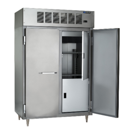
Master Bilt IHC-27 Installation & Operation Manual
Refrigeration solutions
Hide thumbs
Also See for IHC-27:
- Specification sheet (2 pages) ,
- Installation & operation manual (13 pages)
Summary of Contents for Master Bilt IHC-27
- Page 1 Installation & Operations Manual Master-Bilt Products 908 Highway 15 North New Albany, MS 38652 Phone: (800) 684-8988 6/17Rev. E 57-02410...
- Page 2 6/17 Rev. E 57-02410...
-
Page 3: Table Of Contents
TABLE OF CONTENTS INTRODUCTION STORE CONDITIONS . .. WARNING LABELS AND SAFETY INSTRUCTIONS ..5 PRE-INSTALLATION INSTRUCTIONS .......6 Inspection for Shipping Damage ..6 INSTALLATION INSTRUCTIONS General Instructions Mechanical .. Electrical Leg and Condensate Pan Installation.. . -
Page 4: Introduction
INTRODUCTION ® Thank you for purchasing a Master-Bilt cabinet. This manual contains important instructions for installing, using, ® and servicing a Master-Bilt IHC case. A parts list is included with this manual. Read all these documents carefully before installing or servicing your equipment. STORE CONDITIONS ®... -
Page 5: Warning Labels And Safety Instructions
WARNING LABELS AND SAFETY INSTRUCTIONS This symbol is the safety-alert symbol. When you see this symbol on your cabinet or in this manual, be alert to the potential for personal injury or damage to your equipment. Be sure you understand all safety messages and always follow recommended precautions and safe operating practices. -
Page 6: Pre-Installation Instructions
PRE-INSTALLATION INSTRUCTIONS INSPECTION FOR SHIPPING DAMAGE You are responsible for filing all freight claims with the delivering truck line. Inspect all cartons and crates for damage as soon as they arrive. If damage is noted to shipping crates or cartons or if a shortage is found, note this on the bill of lading (all copies) prior to signing. -
Page 7: Mechanical
MECHANICAL Remove front grille and check refrigeration lines to see that they are free (not touching each other or compressor). Spin condenser fan blade to see that it is free. Check that all service valves (3) are open. Remove wooden shipping blocks under compressor. Check all refrigeration lines and electrical conduit for rubbing or chaffing, paying particular attention to area where lines enter the cabinet. -
Page 8: Leg And Condensate Pan Installation
LOW TEMPERATURE FREEZERS – “IHC” Models The IHC has a power cord (15A, 230 Volt) on top of the cabinet at the right rear for connection to power. On initial start-up the evaporator fan motors will not start and you cannot initiate a defrost until the evaporator coil temperature has lowered to 25°F. -
Page 9: Temperature Sensor, Defrost Heater And Fan Motor Replacement
Temperature sensor, defrost heater and fan motor replacement Before making any change, technician should: 1. Disconnect power to the cabinet 2. Remove screws from venturi and pull down ROOM TEMP. SENSOR FAN DELAY/DEFROST TERMINATION SENSOR MOTOR EVAP. COIL MOTOR DEFROST HEATER HEATER SHIELD VENTURI... -
Page 10: Electronic Refrigeration Control
® MASTER-BILT ELECTRONIC REFRIGERATION CONTROL Display Lay-out Compressor When power is first turned on to the control, the controller will go through the start-up delay. After one-minute delay the compressor comes on. The LED for cooling indicator stays on while compressor relay is energized. - Page 11 HOW TO CHANGE THE SETPOINT HOW TO CHANGE a parameter value NOTE 1: The set value is stored even when the procedure is exited by waiting the time-out to expire. ® NOTE 2: Master-Bilt SETPOINT is set at a recommended –25°F at the factory. NOTE 3: To scroll down the parameters without changing them, press the DOWN button.
-
Page 12: Sensor Temperature And Resistance
Check condensing unit for vibrating or rubbing tubing. Dampen and clamp as required. All valves should be completely opened counter-clockwise. Check packing nuts on all service valves. Replace all service valve caps and latch unit covers. Accessories Description IHC-27 IHC-48 Casters (4) 5” diameter A297-11140 A297-11140 Tray Slides 9/16”... -
Page 13: Part Numbers
MASTER-BILT PART LIST ® The table below gives Master-Bilt part numbers. Use this chart when ordering replacement parts for your IHC cabinets. Always Advise Cabinet Serial Number When Ordering Parts Description IHC-27 IHC-48 Coil Defrost Heater 17-00442 17-09076 Compressor 03-14403... -
Page 14: Wiring Diagram
REVISION B DATE MODEL(S) 6/13/17 3/6/15 IHC 27, 48 REVISION A DESCRIPTION 6/23/16 LAE BIT25 CONTROLLER 6/17 Rev. E 57-02410... - Page 15 REVISION B DATE MODEL(S) 6/13/17 3/6/15 IHC 27, 48 REVISION A DESCRIPTION 6/23/16 LAE BIT25 CONTR. REMOTE 6/17 Rev. E 57-02410...
- Page 16 REVISION B DATE MODEL(S) 6/13/17 3/6/15 IHC 27, 48 REVISION A DESCRIPTION 6/23/16 LAE BIT25 BOOSTING TRANS 6/17 Rev. E 57-02410...


Need help?
Do you have a question about the IHC-27 and is the answer not in the manual?
Questions and answers