VIA Technologies ARTiGO A820 User Manual
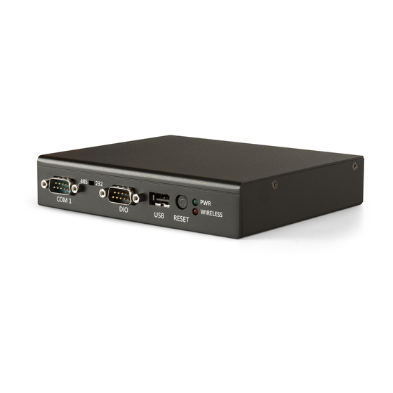
Ultra slim fanless low-profile
gateway system
Hide thumbs
Also See for ARTiGO A820:
- User manual (49 pages) ,
- Quick start manual (28 pages) ,
- Development manual (10 pages)

Subscribe to Our Youtube Channel
Related Manuals for VIA Technologies ARTiGO A820


Summary of Contents for VIA Technologies ARTiGO A820
- Page 1 USER MANUAL ARTiGO A820 Ultra Slim Fanless Low-profile Gateway System 1.05-05182018-112400...
- Page 2 VIA Technologies, Inc. reserves the right the make changes to the products described in this manual at any time without prior notice. Regulatory Compliance FCC-A Radio Frequency Interference Statement This equipment has been tested and found to comply with the limits for a class A digital device, pursuant to part 15 of the FCC rules.
-
Page 3: Safety Precautions
Battery Recycling and Disposal Only use the appropriate battery specified for this product. Do not re-use, recharge, or reheat an old battery. Do not attempt to force open the battery. Do not discard used batteries with regular trash. Discard used batteries according to local regulations. Safety Precautions Always read the safety instructions carefully. -
Page 4: Box Contents
ARTiGO A820 User Manual Box Contents ATG-A820-3D10A2 1 x ARTiGO A820 system 1 x AC-to-DC adapter 1 x Power cord (USA type) 1 x Console cable 1 x Screw pack for miniPCIe module 1 x Rubber feet pack Ordering Information... -
Page 5: Table Of Contents
ARTiGO A820 User Manual Table of Contents 1. Product Overview ........................1 1.1. Key Features ............................1 1.1.1. ARM Based System ............................. 1 1.1.2. Ultra Slim and Space Saving........................1 1.1.3. Optimize Integration with Multiple I/O Access ................... 1 1.1.4. - Page 6 ARTiGO A820 User Manual 5.1. Linux Support ..........................34 5.1.1. Driver Installation ............................. 34 5.2. Technical Supports and Assistance ................... 34...
- Page 7 Figure 39: Securing the top cover ..........................29 Figure 40: Installing the rubber feet ..........................30 Figure 41: Installing the VESA bracket ......................... 31 Figure 42: Installing the VESA plate ..........................32 Figure 43: Installing the ARTiGO A820 system to the VESA plate ............... 33...
- Page 8 ARTiGO A820 User Manual List of Tables Table 1: USB 2.0 ports pinouts ............................9 Table 2: DIO port pinouts..............................9 Table 3: COM port pinouts ............................10 Table 4: DC-in jack pinouts ............................11 Table 5: HDMI port pinouts ............................12 Table 6: Gigabit Ethernet port pinouts ........................
-
Page 9: Product Overview
1.1.2. Ultra Slim and Space Saving The ARTiGO A820 has an ultra slim chassis, designed to save space that makes it suitable to install in space critical environment and to ensure maximum reliability. Its chassis design has a robust aluminum alloy top cover and steel bottom chassis. -
Page 10: Mounting Solution
ARTiGO A820 User Manual 1.1.7. Mounting Solution The ARTiGO A820 supports multiple methods for mounting. It can be mounted to VESA mountable surfaces or even to wall with the VESA mounting kit (optional). 1.1.8. Embedded OS ready The ARTiGO A820 is 100% compatible with Linux Kernel 3.0.35 operating system. -
Page 11: Product Specifications
ARTiGO A820 User Manual 1.2. Product Specifications Processor o 1.0GHz NXP i.MX 6DualLite dual-core Cortex-A9 SoC System Memory o 1GB DDR3 SDRAM onboard Storage o 4GB eMMC Flash memory o One Micro SD card slot (supports up to 32GB) Graphics... - Page 12 ARTiGO A820 User Manual Left Side Panel o 1 x Kensington lock hole Bottom Panel I/O (open window with removable cover) o 1 x MiniPCIe slot o 1 x Micro SD card slot o 1 x Micro SD/SPI boot select switch...
- Page 13 ARTiGO A820 User Manual Software Compatibility (Operating System) o Linux Kernel 3.0.35 Notes: 1. As the operating temperature provided in the specifications is a result of the test performed in VIA’s chamber, a number of variables can influence this result. Please note that the working temperature may vary depending on the actual situation and environment.
-
Page 14: Panel Layout
ARTiGO A820 User Manual 1.3. Panel Layout Figure 1: Front panel I/O layout Figure 2: Back panel I/O layout Figure 3: Left side panel layout... -
Page 15: Dimensions
ARTiGO A820 User Manual 1.4. Dimensions Figure 4: Front side view dimension Figure 5: Left side view dimension Figure 6: Bottom side view dimension... -
Page 16: External I/O Pin Descriptions And Functionality
Wireless LED flashes in red and indicates the activity status of Wi-Fi. Figure 7: LEDs indicator diagram 2.2. Reset Button The ARTiGO A820 comes with a reset button on the front panel. The reset button allows the user to reboot or reset the system forcibly. Figure 8: Reset button diagram 2.3. -
Page 17: Dio Port
2.5. COM Port The ARTiGO A820 is equipped with one COM port (male DE-9 connector) located on the front panel. The COM port can be configured to operate in RS-232 or RS-485 mode. The pinout of the COM port are shown below. -
Page 18: Table 3: Com Port Pinouts
ARTiGO A820 User Manual Signal DCD1 SIN1(Rx) SOUT1(Tx) DTR1 DSR1 RTS1 CTS1 Table 3: COM port pinouts... -
Page 19: Rs-232/Rs-485 Select Switch
The switch is small and only accessible by thin object. Use a pin or end of a paper clip to access the switch. 2.7. DC-In Jack The ARTiGO A820 comes with a DC power input jack on the back panel that carries 5V DC external power input. -
Page 20: Hdmi ® Port
2.8. HDMI Port The ARTiGO A820 has one HDMI port located on the back panel. The HDMI port uses an HDMI port (19-pin) Type A receptacle connector defined in HDMI specification. It is used to connect high definition video and digital audio using a single cable. -
Page 21: Gigabit Ethernet Port
2.9. Gigabit Ethernet Port The ARTiGO A820 is equipped with a Gigabit Ethernet port. The Gigabit Ethernet port is using 8 Position 8 Contact (8P8C) receptacle connector or commonly referred to as RJ-45. It is fully compliant with IEEE 802.3 (10BASE-T), 802.3u (100BASE-TX), and 802.3ab (1000BASE-T) standards. -
Page 22: 10/100Mbps Ethernet Port
ARTiGO A820 User Manual 2.10. 10/100Mbps Ethernet Port The 10/100Mbps Ethernet port (Fast Ethernet) is fully compliant with IEEE 802.3 (10Base-T), (100Base-TX), and (100Base-FX) standards. The 10/100Mbps Ethernet port is controlled by Fast Ethernet module through onboard USB pin header interface. The pinout of the 10/100Mbps Ethernet port are shown below. -
Page 23: Onboard I/O
This chapter provides information about the onboard slots, connector, and switch. 3.1. MiniPCIe Slot The ARTiGO A820 is equipped with one MiniPCIe slot for wireless networking option such as 3G/Wi-Fi module. The MiniPCIe slot is compatible with miniPCIe 2.0 modules that has full-length or half length in size. -
Page 24: Table 10: Minipcie Slot Pinouts
ARTiGO A820 User Manual JTAG_nTRST LED_WPAN_B JTAG_nSRST VCC15 MPCIE_3V3 Table 10: MiniPCIe slot pinouts... -
Page 25: Micro Sd Card Slot
3.2. Micro SD Card Slot The ARTiGO A820 comes with a Micro SD card slot located on the bottom side of the chassis. The Micro SD card slot offers expandable storage of Micro SD card memory up to 32GB capacity. -
Page 26: Console Debug Connector
ARTiGO A820 User Manual 3.4. Console Debug Connector The ARTiGO A820 is equipped with an onboard Console debug connector on the bottom side of the chassis. The Console debug connector is used to attach the Console cable for debugging purposes. -
Page 27: Hardware Installation
ARTiGO A820 User Manual 4. Hardware Installation This chapter provides information about hardware installation procedures. 4.1. Installing the Micro SD Card Step 1 Locate the bottom access cover of the chassis. Loosen the screw to remove the bottom access cover. - Page 28 ARTiGO A820 User Manual Note: To remove the Micro SD card, press the card to disengage from the slot reader then gently pull out the card.
-
Page 29: Installing The Minipcie 3G/Wi-Fi Module And Antenna
ARTiGO A820 User Manual 4.2. Installing the miniPCIe 3G/Wi-Fi module and antenna Step 1 Align the notch on the miniPCIe 3G/Wi-Fi module with the protruding wedge on the miniPCIe slot then insert the module at a 30° angle. Figure 23: Inserting miniPCIe 3G/Wi-Fi module Step 2 Once the module is fully inserted, push down the module until the screw holes align with the standoff hole. -
Page 30: Figure 26: Unscrewing The Top Cover
ARTiGO A820 User Manual Step 3 Remove six screws of the top cover from left, right and bottom side of the chassis, and then remove four hex stand screws of COM and DIO ports. Figure 26: Unscrewing the top cover Step 4 Slide the top cover horizontally to disengage it from the chassis then pull up to remove the top cover. -
Page 31: Figure 28: Removing The Antenna Hole Cover
ARTiGO A820 User Manual Figure 28: Removing the antenna hole cover Step 6 Insert the 3G/Wi-Fi antenna cable into the antenna hole from the inside of the chassis. Insert the washer, fasten it with the nut and install the external antenna. Insert the other end of the antenna cable into the available space going down to the bottom side of the system. -
Page 32: Figure 30: Connecting The 3G/Wi-Fi Antenna Cable To The Micro-Rf Connector
ARTiGO A820 User Manual Step 7 Connect the other end of the 3G/Wi-Fi antenna cable to the micro-RF connector on the miniPCIe 3G/Wi-Fi module. Figure 30: Connecting the 3G/Wi-Fi antenna cable to the micro-RF connector Step 8 Reinstall the bottom access cover. -
Page 33: Installing The Usb Wi-Fi Module (Optional)
ARTiGO A820 User Manual 4.3. Installing the USB Wi-Fi module (optional) Step 1 Locate the mounting holes for the USB WiFi module (VNT9271). The mounting holes have two standoffs premounted inside the chassis. Step 2 Align the two mounting holes on the USB Wi-Fi module with the mounting holes on the standoffs. Secure the USB Wi-Fi module in place with two srews. -
Page 34: Figure 34: Removing The Antenna Hole Cover
ARTiGO A820 User Manual Step 4 Remove the Wi-Fi antenna hole cover from the back panel. To facilitate removing the cover, use a pair of needle-nose pliers to depress both locking clips simutaneously. Figure 34: Removing the antenna hole cover Step 5 Insert the Wi-Fi antenna cable into the antenna hole from the inside. -
Page 35: Figure 36: Installing The Wi-Fi Antenna
ARTiGO A820 User Manual Step 6 Connect the other end of the Wi-Fi antenna cable to the micro-RF connector labeled “MAIN” on the USB Wi- Fi module, and then attach the Wi-Fi antenna to the antenna jack. Figure 36: Installing the Wi-Fi antenna... -
Page 36: Connecting The Console Cable
ARTiGO A820 User Manual 4.4. Connecting the Console cable Step 1 Remove the bottom access cover. Step 2 Gently attach the Console cable onto the onboard Console debug connector. Figure 37: Connecting Console cable Step 3 After debugging, remove the Console cable then reinstall the bottom access cover. -
Page 37: Reinstalling The Top Cover
ARTiGO A820 User Manual 4.5. Reinstalling the top cover Step 1 Mount the top cover and then gently push backward the top cover until it completely covers the top side of the chassis. Figure 38: Installing the top cover Step 2 Once the top cover is installed in place, secure the top cover with six screws. -
Page 38: Installing The Rubber Feet (Optional)
ARTiGO A820 User Manual 4.6. Installing the Rubber feet (optional) Step 1 Locate the designated areas for rubber feet on the bottom side of the chassis. Step 2 Attach each rubber foot and firmly press it down to ensure the rubber foot is properly in place. -
Page 39: Installing The Vesa Mounting Kit (Optional)
ARTiGO A820 User Manual 4.7. Installing the VESA mounting kit (optional) An optional VESA mounting kit is available for mounting the ARTiGO A820 behind the monitor or wall. Step 1 Attach the VESA bracket on the back of the ARTiGO A820 using four M4 x 6mm screws. -
Page 40: Figure 42: Installing The Vesa Plate
ARTiGO A820 User Manual Figure 42: Installing the VESA plate... -
Page 41: Figure 43: Installing The Artigo A820 System To The Vesa Plate
ARTiGO A820 User Manual Step 3 Slide the ARTiGO A820 system into the VESA plate. Then connect all the necessary cables on the back panel of the system. Figure 43: Installing the ARTiGO A820 system to the VESA plate... -
Page 42: Software And Technical Supports
ARTiGO A820 User Manual 5. Software and Technical Supports 5.1. Linux Support The VIA ARTiGO A820 features a complete software evaluation image featuring Linux Kernel 3.0.35 operating system. 5.1.1. Driver Installation Support and drivers are provided through various methods including: •...
Need help?
Do you have a question about the ARTiGO A820 and is the answer not in the manual?
Questions and answers