Table of Contents
Advertisement
Quick Links
SPECIALIZED QUICK-START GUIDE
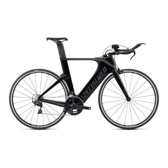
SHIV (LIMITED EDITION)
This quick-start guide is specific to the Shiv bicycle. It contains important
information about assembly and safety, which you should read before your
first ride and keep for reference.
Your new Shiv User Manual is available for download.
Go to:
http://media.specialized.com/support/
collateral/0000137652.pdf, or use the QR code to
download the manual.
A quick-start video is also available for reference
(http://servicevideos.specialized.com/video/325542736).
You should also read the entire Specialized Bicycle Owner's Manual
("Owner's Manual"), because it has additional important general
information and instructions which you should follow. If you do not have
a copy of the Owner's Manual, you can download it at no cost at
specialized.com, or obtain it from your nearest Authorized Specialized
Retailer or Specialized Rider Care.
Additional languages of this document may be available for download at
www.specialized.com.
When reading this user manual, you will note various important symbols
and warnings, which are explained below:
WARNING! The combination of this symbol and word
indicates a potentially hazardous situation which, if not
avoided, could result in serious injury or death. Many of the
Warnings say "you may lose control and fall." Because any
fall can result in serious injury or even death, we do not
always repeat the warning of possible injury or death.
CAUTION: The combination of the safety alert symbol
and the word CAUTION indicates a potentially hazardous
situation, which, if not avoided, may result in minor or
moderate injury, or is an alert against unsafe practices.
The word CAUTION used without the safety alert symbol
indicates a situation which, if not avoided, could result in
serious damage to the bicycle or the voiding of your warranty.
INFO: This symbol alerts the reader to information which is
particularly important.
GREASE: This symbol means that high quality grease should
be applied as illustrated.
CARBON FRICTION PASTE: This symbol means that carbon
friction paste should be applied as illustrated to increase
friction.
TORQUE: This symbol highlights the correct torque value
for a specific bolt. In order to achieve the specified torque
value, a quality torque wrench must be used.
TECH TIP: Tech Tips are useful tips and tricks regarding
installation and use.
INTENDED USE
The Shiv is intended and tested for Road Riding only (Condition 1). For more
information on intended use and structural weight limits, please refer to the
Owner's Manual.
WARNING! The Specialized carbon components on the Shiv
bicycle are designed for a maximum rider weight of 240
lb (109 Kg). Do not ride these components if your weight,
including any gear and accessories you are wearing, exceeds
this weight limit. Failure to follow this warning may result in an
accident, which can cause serious injury or death.
This quick-start guide covers basic steps to complete the assembly of the
cockpit and reservoir, as well as how to adjust the cockpit for fit. For more
detailed information about setting Basebar angles, wiring information, how
to fully assemble or disassemble the bike and how to prepare for travel,
please refer to the complete User Manual, available at www.specialized.com.
SEATPOST:
www.
The wedge assembly in front of the seatpost can be accessed by lifting
„
the rubber cover up the seatpost.
A sight hole is located behind the seat tube to determine minimum
„
seatpost extension.
COCKPIT:
The cockpit has 0-115mm of stack height adjustment. (p.3).
„
The Crossbar can be positioned in front or behind the Extension
„
Socket, for more or less reach (fig.7).
The Arm Cups have multiple positions based on fit preference.
„
•
Arm Cup mounting: Four (outboard) or two (inboard) lateral positions
•
Three fore-aft Arm Cup positions
•
The Arm Cups can also be rotated slightly to fine-tune the position
A wedge can be placed beneath the Arm Cups to provide angle (fig.9).
„
The extensions can be rotated inboard or outboard for additional fine-
„
tuning of the position.
An additional mount can be installed on the extensions to mount a
„
digital device or optional bottle cage (fig.11).
The cockpit can be removed as a complete assembly for travel.
„
BASEBAR:
The Basebars can be set at 0, +20 or -20 degree angles, depending on
„
the spacer stack height and rider preference.
The Basebars can be lowered alongside the bike for travel.
„
NOSECONE:
The nosecone clip can be removed to unplug the Di2 wires for travel.
„
FUELCELL:
The Fuelcell is a two-part system. One part in the down tube for solid
„
foods and gels, and one part behind the seat tube inside the reservoir
for fluids.
The Hydration Fuelcell can be removed for cleaning and travel, or
„
replaced with a new one.
JUNCTION BOX:
Bikes equipped with Shimano Di2 have the Junction A box positioned
„
above the Nutrition Fuelcell in the down tube. Remove the Fuelcell to
access the charge port.
BIKE OVERVIEW
1
Advertisement
Table of Contents

Related Manuals for Specialized SHIV


Summary of Contents for Specialized SHIV
- Page 1 INTENDED USE JUNCTION BOX: The Shiv is intended and tested for Road Riding only (Condition 1). For more Bikes equipped with Shimano Di2 have the Junction A box positioned „ information on intended use and structural weight limits, please refer to the above the Nutrition Fuelcell in the down tube.
- Page 2 DESCRIPTION TOOL SIZE in-lbf DESCRIPTION TOOL SIZE in-lbf FRAME ARM CUPS FORK ARM CUP WEDGE BASEBAR ARM CUP BOLTS BASEBAR SPINDLE 3mm (two bolts per spindle) ARM CUP PLATES BASEBAR WEDGE 13.5 EXTENSIONS BASEBAR HOOD SEATPOST (SADDLE CLAMP) 13.5 NOSECONE CLIP SEATPOST WEDGE TOWER STUDS 4mm hex / 8mm open...
- Page 3 INITIAL ASSEMBLY / CHANGING FIT Your Shiv comes pre-assembled, minus the front wheel and the cockpit assembly. Before assembling the cockpit, it is recommended to be fit to the bike. The table below explains the required Tower Stud length for the desired Spacer Stack.
- Page 4 USE EITHER A 4MM ALLEN KEY AND TORQUE FROM BELOW, OR USE AN 8MM OPEN WRENCH AT THE BASE OF THE TOWER STUD Fig.1: Loosen the Basebar wedge bolts just enough to allow the Basebars „ to rotate up and level with the ground. Fig.4: The Tower Studs can be tightened either with a 4mm Hex key from underneath the upper fork bridge, or with an 8mm open wrench from the upper side.
- Page 5 MIN: MAX: 12mm 20mm Fig.9: Grease then install the lockplate inside each Crossbar cavity „ prior to installing the extensions. FIG.6 WARNING! Always use the proper Tower Stud length A dab of grease behind the Crossbar Lockplate can help retain that corresponds to the chosen Spacer Stack shown in the the Lockplate in place while installing the extension.
- Page 6 0000137653_QS_EN_R3, 07/19 the stack until it sticks out the front of the nosecone. We may occasionally issue updates and addendums to this document. Please periodically check www.specialized.com or contact Rider Care to make sure you have the latest information. Insert the plug and tether into the opening of the drinking tube.
Need help?
Do you have a question about the SHIV and is the answer not in the manual?
Questions and answers