Table of Contents
Advertisement
Quick Links
Advertisement
Table of Contents

Related Manuals for Eaton XN-312-GW-EC


Summary of Contents for Eaton XN-312-GW-EC
- Page 1 Manual 07/20 MN050010-EN EtherCAT gateway XN-312-GW-EC...
- Page 2 All editions of this document other than those in German language are trans- lations of the original operating manual. 1st edition 2020, publication date 07/20 © 2020 by Eaton Industries GmbH, 53105 Bonn Authors: Thomas Hettwer, Andreas Lüngen, Klaus-Dieter Moeller Editor: Bettina Ewoti All rights, including those of translation, reserved.
- Page 3 Danger! Dangerous electrical voltage! Before starting with the installation • Disconnect the power supply of the device. • Ensure a reliable electrical isolation of the low voltage for the 24 V supply. Only use power supply units complying • Secure against retriggering with IEC 60364-4-41 or HD 384.4.41 S2 (VDE 0100 Part 410).
-
Page 5: Table Of Contents
Supply voltage connection ............18 LED status indicators ..............19 Potential relationship between the components ......21 The EtherCAT finite state machine .......... 23 XN-312-GW-EC gateway object dictionary......25 Communication area ..............25 4.1.1 Device type (0x1000) ..............27 4.1.2 Device name (0x1008) .............. - Page 6 4.3.9 System bus configuration (0×FB10) ..........42 XN300 I/O module support............43 Module ID number............... 43 XN-322 slice modules supported by the XN-312-GW-EC .... 44 Operating modes ............... 45 Free run ..................45 Distributed clocks (DC synchronous) ........... 45 Device description files for EtherCAT (XML/ESI)....47 Installation..................
- Page 7 Diagnostics messages ..............85 12.7 What will be transferred............... 87 12.7.1 Implementing the start parameter PDOs and SDOs....87 12.7.2 Start parameters for XN-312-GW-EC gateway......87 12.7.3 Process data XN-312-GW-EC gateway ........90 12.7.4 ONLINE CoE XN-312-GW-EC gateway ........90 12.8 Finding XN300 slice module PDOs and SDOs ......
- Page 8 13.5.1 Enabling distributed clocks ............118 13.5.2 Redundancy ................. 118 13.5.3 Watchdog ..................119 13.6 System limits ................120 13.7 Further reading and links.............. 121 Index ................... 123 XN-312-GW-EC gateway 07/20 MN050010-EN www.eaton.com...
-
Page 9: About This Manual
Fault-free and safe operation of the sys- tem requires proper transport, storage, installation and commissioning as well as careful operation and maintenance. If the following safety instruc- tions are not observed, particularly with regard to commissioning and mainte- XN-312-GW-EC gateway 07/20 MN050010-EN Eaton.com... -
Page 10: Device Designations And Abbreviations
TPDO - Transmit Process Data Objects • XN300 - Device series, including the XN-312 gateway and XN-322 slice modules • XML - EXtensible Markup Language; description file for representing hierarchically structured data in text file format XN-312-GW-EC gateway 07/20 MN050010-EN Eaton.com... -
Page 11: Writing Conventions
→ Indicates useful tips. ▶ Indicates instructions to be followed. For greater clarity, the name of the current chapter and the name of the cur- rent section are shown at the top of each page. XN-312-GW-EC gateway 07/20 MN050010-EN Eaton.com... - Page 12 0 About this manual 0.5 Writing conventions XN-312-GW-EC gateway 07/20 MN050010-EN Eaton.com...
-
Page 13: Ethercat - General Information
Ethernet data packet to reach every single node in both the transmission and reception directions so that these nodes can process the corresponding data. This makes it possible to make full use of the full-duplex properties of 100BASE-TX, achieving a payload data rate of over 90%. XN-312-GW-EC gateway 07/20 MN050010-EN Eaton.com... -
Page 14: Protocol Properties
Figure 2: EtherCAT: Standard Ethernet frame as defined in IEEE 802.3 An EtherCAT frame contains one or more datagrams and can be made up of multiple subframes so as to transmit large amounts of data. XN-312-GW-EC gateway 07/20 MN050010-EN Eaton.com... -
Page 15: Modular Device Profile
Within the context of EtherCAT, a modular device is a device with modular and functional expansion options. The XN-312-GW-EC EtherCAT gateway conforms to the Modular Device Pro- file (MDP) as defined in the EtherCAT specification (ETG 5001) based on CoE (CANopen over EtherCAT). - Page 16 As per the MDP, there are two defined areas in the object dictionary: • Communication area • Device parameter area → File Access over EtherCAT (FoE), Servo Profile over EtherCAT (SoE), and Ethernet over EtherCAT (EoE) are not supported as of this writing. XN-312-GW-EC gateway 07/20 MN050010-EN Eaton.com...
-
Page 17: Xn-312-Gw-Ec Gateway
2 XN-312-GW-EC gateway 2.1 Proper use XN-312-GW-EC gateways are part of the XN300 system. They act as Ether- CAT devices and make it possible to connect an XN300 I/O group to a con- troller's EtherCAT master using the EtherCAT field bus system. In fact, the XN-312-GW-EC gateway supports groups of up to 32 XN300 slice modules. -
Page 18: Overview Of Functions
I/O slice module configuration to the EtherCAT master. Figure 4: The XN-312-GW-EC gateway can be used to establish a connection to an Ether- CAT field bus. The RJ45 X1 (EtherCAT IN) and X2 (EtherCAT OUT) ports are used to estab- lish a connection to the network. -
Page 19: Versions
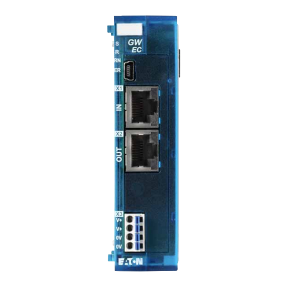
④ ⑥ ⑦ ⑧ ⑨ Figure 5: Front view of XN-312-GW-EC a LED S, Sync status b R LED, Reset status c LED RN, EtherCAT Run status d EC LED, EtherCAT error status e Mini-USB diagnostic interface f EtherCAT IN g EtherCAT OUT h Power supply, 24 VDC POW –... -
Page 20: Field Bus Connection
The configuration of the terminal sockets at the gateway X1 EtherCAT IN b X2 EtherCAT OUT a LED IN yellow b LED OUT yellow EtherCAT IN Function Tx+/Rx+ Tx-/Rx- Rx+/Tx+ 4, 5 – RX-/Tx- 7, 8 – XN-312-GW-EC gateway 07/20 MN050010-EN Eaton.com... -
Page 21: Diagnostics Interface
Function – 7, 8 – 2.5 Diagnostics interface The diagnostic interface on the XN-312-GW-EC can be used to establish a connection to a PC in order to download firmware or connect XN300-Assist to the EtherCAT gateway. ① Figure 7: Mini USB 2.0 type B diagnostic port Mini USB 2.0 type B... -
Page 22: Supply Voltage Connection
10 mm (0.39“) 0.25 - 0.75 mm AWG 24 - 16 ⌀d2 Figure 9: Ferrule with d2 = Max. 2.8 mm → The spring-cage terminals can be used to connect ultrasonically spliced (ultrasonically welded) wires. XN-312-GW-EC gateway 07/20 MN050010-EN Eaton.com... -
Page 23: Led Status Indicators
What the LEDs mean Color EtherCAT status Description S (Sync) green Continuous light System bus running synchronously – System bus not running synchronously R (Reset) System bus RESET in progress – System bus currently not being reset XN-312-GW-EC gateway 07/20 MN050010-EN Eaton.com... - Page 24 Connection to downstream EtherCAT node established Flashing Data communication with downstream EtherCAT node established – No connection to downstream EtherCAT node X3 (DC power OK) green Continuous light +24 VDC power OK – +24 VDC power faulty XN-312-GW-EC gateway 07/20 MN050010-EN Eaton.com...
-
Page 25: Potential Relationship Between The Components
+24 V DC, 1.6 A BP_24V XN-312 XN-322 XN-322 CPU system n = 1 n = ≦ 31 +5 V DC, 1.6 A BP_5V DC (24 V DC) Figure 11: Function principle of XN300 system XN-312-GW-EC gateway 07/20 MN050010-EN Eaton.com... - Page 26 2 XN-312-GW-EC gateway 2.8 Potential relationship between the components XN-312-GW-EC gateway 07/20 MN050010-EN Eaton.com...
-
Page 27: The Ethercat Finite State Machine
3 The EtherCAT finite state machine 3 The EtherCAT finite state machine The are various states and state transitions that are defined in the EtherCAT protocol. XN-312-GW-EC gateways implement these EtherCAT states using the system bus for communication with the XN300 slice modules. Figure 12:... - Page 28 • The system bus is starting with the PDOs -> OPERATIONAL for the outputs. OPERATIONAL The device has been initialized and is active. PDOs are being written to the master. Inputs are being read. Outputs will be written. XN-312-GW-EC gateway 07/20 MN050010-EN Eaton.com...
-
Page 29: Xn-312-Gw-Ec Gateway Object Dictionary
4 XN-312-GW-EC gateway object dictionary 4.1 Communication area 4 XN-312-GW-EC gateway object dictionary For more detailed information on the object dictionary, the basic structure of the individual objects, and the modular device profile used, please refer to the corresponding EtherCAT specifications: •... - Page 30 4 XN-312-GW-EC gateway object dictionary 4.1 Communication area Table 2: Object overview l Index Name M - Mandatory O - Optional C - Conditional 0x1000 Device type (0×00005001) 0x1008 Device name (XN-312-GW-EC) 0x1009 Hardware version 0x100A Software version 0x1018 Identity (device identification) 0×1018/#01...
-
Page 31: Device Type (0X1000)
4 XN-312-GW-EC gateway object dictionary 4.1 Communication area 4.1.1 Device type (0x1000) Object 0x1000 contains the type and function of the EtherCAT device. A value of 0000 1389 indicates that the device is a device with a modular device profile (MDP). -
Page 32: Identity Object (0×1018)
4 XN-312-GW-EC gateway object dictionary 4.1 Communication area Index (hex) Object Name 0x100A manufacturer software version Sub-index Descrip- Default Catalog Access (hex) tion number manufac- – Visible string const turer soft- ware version 4.1.5 Identity object (0×1018) Object 0x1018 contains manufacturer-specific information regarding the XN- 312 gateway. -
Page 33: Txpdo Mapping Object (0×1A00
4 XN-312-GW-EC gateway object dictionary 4.1 Communication area Within this context, an object consists of one or more sub-objects, while the sub-object represents the module channel. For each module, special RxPDO objects that are named based on the mod- ule name and type are created. -
Page 34: Rxpdo Assign Object (0X1C12)
4 XN-312-GW-EC gateway object dictionary 4.1 Communication area 4.1.9 RxPDO assign object (0x1C12) Object 0x1C12 references the RxPDO mapping objects and defines which PDOs should be transmitted with the EtherCAT output data. (Access: RO.) 4.1.10 TxPDO assign object (0x1C13) Object 0x1C13 references the TxPDO mapping objects and defines which PDOs should be transmitted with the EtherCAT input data. -
Page 35: Module Object Area (0×6000 - 0×Afff)
4 XN-312-GW-EC gateway object dictionary 4.2 Module object area (0×6000 - 0×AFFF) 4.2 Module object area (0×6000 - 0×AFFF) Object area Index range Modular device Input data object area 0x6xxx Conditional Output data object area 0x7xxx Conditional Configuration data object... -
Page 36: Output Data Object Area (0×7Xxx)
4 XN-312-GW-EC gateway object dictionary 4.2 Module object area (0×6000 - 0×AFFF) 4.2.2 Output data object area (0×7xxx) An output data object with multiple sub-objects is assigned to every module with output data. The number of sub-objects within this context depends on the module's number of channels. -
Page 37: Module Information (0×9Xxx)
4 XN-312-GW-EC gateway object dictionary 4.2 Module object area (0×6000 - 0×AFFF) Since the 0x8xx1 LED control object is not required for configuration pur- poses, it can be mapped manually or set at runtime using SDO communica- tion. Index (RxPDO) -
Page 38: Device Parameter Area
4 XN-312-GW-EC gateway object dictionary 4.3 Device parameter area Sub-index Descrip- Default Catalog Access (hex) tion number number of – USINT entries module UDINT status (0 = Module OK) device ID 00000000 UDINT FPGA 00000000 UDINT version HW version 00000000... - Page 39 4 XN-312-GW-EC gateway object dictionary 4.3 Device parameter area Index Description / Value Sub-index Sub-index #02 Systembus manager option bits Sub-index #03 Systembus manager FPGA version 0xF101 XN-312-GW-EC info Sub-index #01 Serial Gateway serial number 0xF110 System bus diagnostics Sub-index #01...
-
Page 40: Modular Device Profile Object 0Xf000
4 XN-312-GW-EC gateway object dictionary 4.3 Device parameter area 4.3.1 Modular device profile Object 0xF000 Object 0xF000 contains basic information regarding the modular device pro- file used. Index (hex) Object Name 0xF000 Device type Sub-index Descrip- Default Catalog Access (hex) -
Page 41: Detected Module Ident List (Object 0Xf050)
4 XN-312-GW-EC gateway object dictionary 4.3 Device parameter area 4.3.3 Detected module ident list (Object 0xF050) Object 0xF050 contains a list of the detected XN300 slice modules with the corresponding module ID numbers. Object 0xF050 contains the module IDs for all the XN300 slice modules physically present in an XN300 system block. -
Page 42: System Bus Diagnostics Object 0Xf110
4 XN-312-GW-EC gateway object dictionary 4.3 Device parameter area 4.3.5 System bus diagnostics Object 0xF110 Object 0xF110 contains diagnostic information regarding the system bus. Index (hex) Object Name 0xF110 RECORD System bus diagnostics Sub-index Descrip- Default Catalog Access (hex) tion... -
Page 43: Error Codes
XN-312-GW-EC 4.3.6.1 Error codes The error codes are shown under the CoE tab when using online communi- cation; please refer to → Section “12.7.4 ONLINE CoE XN-312-GW-EC gateway”, page 92 and → Section “12.6 Diagnostics messages”, page 87. Error code... -
Page 44: Reason Codes
4 XN-312-GW-EC gateway object dictionary 4.3 Device parameter area Error code Error information PDO data reading had to be terminated PDO data writing could not be started PDO data writing had to be terminated Attempt to call a function upon a state transition failed... -
Page 45: System Bus Statistics (0×F120)
4 XN-312-GW-EC gateway object dictionary 4.3 Device parameter area Reason code Error information The switch from ISO Full to the Read-Only task state on the system bus failed Excessively long filename Bad checksum 4.3.7 System bus statistics (0×F120) Object 0xF120 contains statistical data regarding the system bus. -
Page 46: System Bus Configuration (0×Fb10)
4 XN-312-GW-EC gateway object dictionary 4.3 Device parameter area 4.3.9 System bus configuration (0×FB10) 0xFB10 contains configuration options for the system bus. Object Index (hex) Object Name 0xFB10 RECORD SDIAS configuration Sub-index Descrip- Default Catalog Access (hex) tion number number of –... -
Page 47: Xn300 I/O Module Support
8009 XN-322-10AI-TEKT 8010 XN-322-8AIO-U2 8011 XN-322-8AIO-I 8012 XN-322-8AO-U2 8013 XN-322-1DCD-B35 8014 XN-322-1CNT-8DIO: 8015 XN-322-2SSI 8016 XN-322-4DO-RNO 8018 XN-322-20DI-ND 8019 XN-322-16DI-PD 8020 XN-322-8DI-PD 8021 XN-322-16DIO-PD05 8022 XN-322-16DIO-PC05 8023 XN-322-8DIO-PD05 8024 XN-322-8DO-P05 8025 XN-322-4AIO-U2 8026 XN-322-4AIO-I 8027 XN-312-GW-EC gateway 07/20 MN050010-EN Eaton.com... -
Page 48: Slice Modules Supported By The Xn-312-Gw-Ec
5.2 XN-322 slice modules supported by the XN-312-GW-EC 5.2 XN-322 slice modules supported by the XN-312-GW-EC The XN-312-GW-EC supports the following XN300 slice modules. The ver- sion is printed on the right side of every XN300 slice module (e.g., "Version: 3.02"). -
Page 49: Operating Modes
6 Operating modes 6.1 Free run 6 Operating modes The XN-312-GW-EC supports free run mode and DC synchronous mode. 6.1 Free run In "free run" mode, input values are applied and output values are output cyclically, with the cycle being based on a timer in the node that functions as a trigger. - Page 50 General distributed clocks diagram a Input values b Output values c Output values are set and input values are read Please note that exact synchronization is always particularly important when spatially distributed processes require simultaneous actions. XN-312-GW-EC gateway 07/20 MN050010-EN Eaton.com...
-
Page 51: Device Description Files For Ethercat (Xml/Esi)
EtherCAT control program. This XML file lists all objects with the associated sub-indexes and the corre- The XN-312-GW-EC gateway, together with the snap-on XN300 modules, is integrated into the EtherCAT structure with the help of a standardized XML file. sponding entries. - Page 52 After installing the new XML file, you can select the new device version from the device selection. If you update an existing proj- ect with a new XML version, you will need to update all the pre- viously installed devices after installing the XML file. XN-312-GW-EC gateway 07/20 MN050010-EN Eaton.com...
-
Page 53: Installation
The gateway is installed in the following order: • Join the gateway and all I/O slice modules to form a system block. • Mount the system block on the DIN-rail. • Connect the power supply. • Connect the field bus. XN-312-GW-EC gateway 07/20 MN050010-EN Eaton.com... -
Page 54: Mounting
8.1 Mounting 8.1 Mounting 8.1.1 Installation prerequisites Install the XN-312-GW-EC gateway in a control panel, a distribution board or an enclosure so that the power supply and terminal capacities cannot be touched accidentally during operation. Snap the device onto an IEC/EN 60715 DIN-rail. - Page 55 Repeat these steps until you have added all the XN300 modules you need to the system block. ▶ Pull the locking elements at the back of the gateway and the XN300 slice modules upwards. You can use a screwdriver to do this. XN-312-GW-EC gateway 07/20 MN050010-EN Eaton.com...
- Page 56 You can use a screwdriver to do this. Figure 21: Locking the system block into place on the DIN-rail ▶ Check to make sure that the system block is solidly mounted. XN-312-GW-EC gateway 07/20 MN050010-EN Eaton.com...
-
Page 57: Dismantling
Disengaging the system block ▶ Tilt the system block forward, then pull the block, from its bottom edge, away from the DIN-rail. Figure 23: Placing the system block against the bottom edge of the DIN-rail XN-312-GW-EC gateway 07/20 MN050010-EN Eaton.com... - Page 58 Disengaging the front cover ▶ Once the locking tabs have been disengaged, you can separate the slice modules and the gateway from each other. Figure 25: Separating the gateway and the XN300 slice modules from the system block XN-312-GW-EC gateway 07/20 MN050010-EN Eaton.com...
-
Page 59: Connecting The Power Supply
V terminals. The internally connected terminals can be used to extend the 24 V and 0 V supply voltage connections. However, it is necessary to make sure that a total current of 6 A is not exceeded per terminal. XN-312-GW-EC gateway 07/20 MN050010-EN Eaton.com... - Page 60 • Fuse 3 A Connection example 24 V DC XN-312-GW-EC XN-322 XN-322 +24 V DC BP_24V ≦ 31 x XN-322 +5 V DC BP_5V Figure 27: Connecting example for XN-312-GW-EC gateway in XN300 system XN-312-GW-EC gateway 07/20 MN050010-EN Eaton.com...
-
Page 61: Connect Field Bus
8.5 Connecting the diagnostics interface The gateway features a Mini-USB port on the front. By using a programming cable, you can connect it to a computer and do the following with the corre- sponding software: XN-312-GW-EC gateway 07/20 MN050010-EN Eaton.com... -
Page 62: Wiring In Accordance With Emc Requirements
DIN-rail FM 4/TS 35 (Weidmüller) ZB4-102-KS1 Figure 29: Field bus shielded by using a shield The gateway features a functional earth contact point on the back. ① Figure 30: XN-312-GW-EC side view a Functional earth XN-312-GW-EC gateway 07/20 MN050010-EN Eaton.com... -
Page 63: Commissioning
9.1 Establishing EtherCAT field bus communications For the EtherCAT master, go to the "General" tab and select the Ethernet port Click that should be used to connect to the EtherCAT gateway. XN-312-GW-EC gateway 07/20 MN050010-EN Eaton.com... - Page 64 PLC via the field bus. → If the field bus address on the gateway changes, the change will not take effect for the communication on the field bus until after the gateway is turned off and then back on. XN-312-GW-EC gateway 07/20 MN050010-EN Eaton.com...
-
Page 65: Status Indicators When Field Bus Communications Are Successfully Established
If an XN300 slice module is removed from, added to, or replaced on the system bus, you will need to switch off the power sup- ply. If a configuration change is made during ongoing operation, this will always result in the gateway being reset. XN-312-GW-EC gateway 07/20 MN050010-EN Eaton.com... - Page 66 9 Commissioning 9.2 Status indicators when field bus communications are successfully established XN-312-GW-EC gateway 07/20 MN050010-EN Eaton.com...
-
Page 67: Xn300-Assist
<F1> key. 10.1 Firmware update with XN300-Assist Eaton may make new operating systems available in order to provide new functionalities; Download Center → Page 121. For more information on how to update the operating system for the XN-312- GW-EC gateway with the help of XN300-Assist, please refer to the online help for XN300-Assist. - Page 68 10 XN300-Assist 10.1 Firmware update with XN300-Assist XN-312-GW-EC gateway 07/20 MN050010-EN Eaton.com...
-
Page 69: Configuring An Ethercat System With Xsoft-Codesys
Before commissioning an EATON PLC (e.g. XC303, XV300) with XSOFT- CODESYS-3 programming software, the PLC needs to be connected to a programming computer. To do this, the EATON PLC first needs to be con- nected to the XN-312-GW-EC EtherCAT gateway using an Ethernet cable. -
Page 70: General Instructions For Working With Xsoft-Codesys-3
▶ Finally, you would move the cursor between "Bit length" and "Abort in case of error" and drag the border between the two to the right. XN-312-GW-EC gateway 07/20 MN050010-EN Eaton.com... - Page 71 11 Configuring an EtherCAT system with XSOFT-CODESYS 11.1 General instructions for working with XSOFT-CODESYS-3 Figure 35: Table in in XSOFT-CODESYS-3 showing all the columns XN-312-GW-EC gateway 07/20 MN050010-EN Eaton.com...
-
Page 72: Configuring The System With Xsoft-Codesys-3
Now use the "PLC_PRG in" drop-down menu to select the programming language you want, e.g., "Structured Text (ST)". Figure 36: Configuring a standard project ▶ Confirm the PLC information being displayed by clicking on "OK." The device will be added to the project. XN-312-GW-EC gateway 07/20 MN050010-EN Eaton.com... -
Page 73: Configuring The Ethercat Master
<Add Device...> option in the context menu. The "Add device" dialog box will appear if it is not open already. ▶ Select <Field buses | EtherCAT | Slave | Eaton Industries GmbH | Gate- ways | XN-312-GW-EC | Add Device>. XN-312-GW-EC gateway 07/20 MN050010-EN... - Page 74 To do so, go to the "EtherCAT Master/General" tab and click on the "Browse..." button. The "Select Network Adapter" dialog box will appear. ▶ Select the EtherCAT master Ethernet port you want ("ETH1," for exam- ple). ▶ Confirm your selection by clicking on "OK". XN-312-GW-EC gateway 07/20 MN050010-EN Eaton.com...
-
Page 75: Configuring Ethercat Devices
EtherCAT master parameters Baud rate of the EtherCAT master The baud rate for the EtherCAT master (XC303 in this case) and the Ether- CAT device (XN-312-GW-EC in this case) is fixed at full-duplex 100 Mbit/s. 11.2.3 Configuring EtherCAT devices ▶... -
Page 76: Configuring The Xn312 Gateway
11.2 Configuring the system with XSOFT-CODESYS-3 Figure 41: Adding an EtherCAT device ▶ Select the EtherCAT device you want (XN-312-GW-EC, for example). ▶ Click on the <Add device> button. The selected EtherCAT device will be added to the configuration structure in the "Devices"... -
Page 77: Configuring Xn-322 Slice Modules
XN-312-GW-EC EtherCAT gateway settings 11.2.4.1 Configuring XN-322 slice modules ▶ To configure the system block, right-click on the EtherCAT device, e.g., "XN_312_GW_EC (XN-312-GW-EC...)" in the "Devices" configuration structure. ▶ Then click on the <Add device...> option. The "Add device" dialog box will appear if it is not open already. The dialog box will show a list with all the XN300 slice modules that can be configured. - Page 78 You can change the order of the I/O slice modules in the config- uration structure by dragging and dropping them accordingly. A maximum of 32 I/O slice modules can be added to the EtherCAT device. XN-312-GW-EC gateway 07/20 MN050010-EN Eaton.com...
-
Page 79: Automatic Mapping
In the relevant "Supported objects" section. ▶ Open the "Process data" tab and check to make sure that all of the I/O slice modules' process data is included in the automatic mapping. Figure 45: Mapping table in "PDO Mapping" tab XN-312-GW-EC gateway 07/20 MN050010-EN Eaton.com... -
Page 80: Configuring Device Initialization Parameters
Enter the default value you want into the "Value" field, e.g., "1". → The "SDOs (Service Data Object)" tab will show default device initialization values with a gray font and modified device initial- ization values with a black font. XN-312-GW-EC gateway 07/20 MN050010-EN Eaton.com... -
Page 81: Adding Ethercat Communication Libraries
By default, all the libraries required for EtherCAT communication will be auto- matically added after the EtherCAT master is added and the project is com- piled for the first time. → For more detailed information, please consult the documenta- tion for the PLC you are using. XN-312-GW-EC gateway 07/20 MN050010-EN Eaton.com... - Page 82 11 Configuring an EtherCAT system with XSOFT-CODESYS 11.2 Configuring the system with XSOFT-CODESYS-3 XN-312-GW-EC gateway 07/20 MN050010-EN Eaton.com...
-
Page 83: Sample Project
There is a detailed description of the objects for each XN300 slice module, as well as the representation of the objects in the XN-312-GW-EC gateway CoE. This sample project uses four XN300 slice modules running on the EtherCAT gateway. - Page 84 Figure 47: "Select Device" dialog box Communications between the PC and the PLC will be established, and this will be shown with "... (active)" in the drop-down menu underneath the PLC. Figure 48: Device(XC303)/Communication tab XN-312-GW-EC gateway 07/20 MN050010-EN Eaton.com...
-
Page 85: Updating The Operating System For The Xc303 Plc
Use X1 to connect XN-322-4AI-PTNI to a temperature sensor as specified in the MN050002 "XN300 slice modules" manual. Select a 3-wire configuration. We are assuming that the temperature sensor is a Pt100 resistance ther- mometer with a temperature range of -200 to +850°C. XN-312-GW-EC gateway 07/20 MN050010-EN Eaton.com... - Page 86 To select a filter frequency of 1 Hz for channel 1, assign AI1_Filterfreq a decimal value of 1. ▶ To select a resolution within the measuring range / reading representa- tion of -10 to +10V with 0.3 mV/LSB, assign the FullRes16Bit start parameter a value of 1. XN-312-GW-EC gateway 07/20 MN050010-EN Eaton.com...
-
Page 87: Monitor Iec Objects
Figure 52: XN_312_GW_EC/EtherCAT IEC objects online tab XN-312-GW-EC gateway 07/20 MN050010-EN Eaton.com... -
Page 88: Going Online And Loading The Program Onto The Plc
The "Update boot application" option will be enabled automatically. Leave it enabled. ▶ Confirm by clicking on OK. ▶ Start the program by pressing function key [F5] or by clicking on the icon in the toolbar. XN-312-GW-EC gateway 07/20 MN050010-EN Eaton.com... -
Page 89: Diagnostics Messages
If communication cannot be successfully estab- lished, you can use the following diagnostic options: EtherCAT_Master/ diagnostics The EtherCAT_Master/General tab provides a general description in the "Diagnostic message" field. Figure 55: Diagnostic message in EtherCAT_Master/General tab XN-312-GW-EC gateway 07/20 MN050010-EN Eaton.com... - Page 90 ErrorCode For more information, please refer to → Section “4.3.6 Error info Object 0xF111”, page 38. Figure 56: ErrorCode diagnostic message in XN_312_GW_EC/CoE tab Error settings Figure 57: Diagnostic message in XN_312_GW_EC/CoE/Online from device tab XN-312-GW-EC gateway 07/20 MN050010-EN Eaton.com...
-
Page 91: What Will Be Transferred
"Start parameters" tab for the corresponding XN300 slice module. The objects are found in address range 0x8000. The mapping of these objects to the objects that must be edited for XN-312-GW-EC gateway in the "Start parameters" tab is as follows: The zeroes in the middle of the object address are replaced with the Modu- leID for the relevant module. - Page 92 12.7 What will be transferred The following specific SDOs and start parameters are the ones in the sample project Figure 58: XN_312_GW_EC/Start parameters tab Start parameters for XN-312-GW-EC gateway; the read start parameters for all XN300 slice modules Object Data type Name...
- Page 93 0x8039# UINT FilterConfigChann Filter Configuration Channel 1 – 0x8039# UINT FilterConfigChann Filter Configuration Channel 2 – 0x8039# UINT FilterConfigChann Filter Configuration Channel 3 – 0x8039# UINT FilterConfigChann Filter Configuration Channel 4 – 0x803C# ~~~‘‘‘‘ XN-312-GW-EC gateway 07/20 MN050010-EN Eaton.com...
-
Page 94: Process Data Xn-312-Gw-Ec Gateway
12 Sample project 12.7 What will be transferred 12.7.3 Process data XN-312-GW-EC gateway The process data for all XN300 slice modules is provided to the XN-312-GW- EC gateway. This data can be found under the XN_312_GW_EC/Process data tab. Outputs are in the 0x7000 range. For the outputs, this means that: •... - Page 95 12 Sample project 12.7 What will be transferred XN-312-GW-EC gateway 07/20 MN050010-EN Eaton.com...
-
Page 96: Finding Xn300 Slice Module Pdos And Sdos
Figure 60: XN_322_8DI_PD/Module I/O image table tab The XN300 slice module's process data is also stored in the XN-312-GW-EC gateway process data, in the 6xxx object range. In the 0x6xxx range, since they are inputs exclusively. The ModuleID in the sample project is 0, which is why the inputs are stored in object 0x6000. -
Page 97: Xn-322-16Do-P05
CoE in the 0x9000 objects. In the case of XN-322-8DI-PD, specifi- cally in object 9000, since it is the first node on the system bus; please refer to → Section “12.7.4 ONLINE CoE XN-312-GW-EC gateway”, page 90. Figure 61: XN_312_GW_EC/CoE Online tab excerpt 12.8.2 XN-322-16DO-P05... - Page 98 Figure 62: XN_322_16DO_P05/Module I/O image table tab The XN300 slice module's process data is also stored in the XN-312-GW-EC gateway process data, in the 0x7xxx object range. In the 0x7xxx range, since they are inputs exclusively. The ModuleID in the sample project is 1, and the outputs are accordingly stored in object 0x7010.
- Page 99 CoE in the 9xxx objects. In the case of XN-322-16DO-P05 specifi- cally in object 9010 because it is the second node on the system bus; please refer to → Section “12.7.4 ONLINE CoE XN-312-GW-EC gateway”, page 90. Figure 63:...
-
Page 100: Xn-322-4Ai-Ptni
Figure 65: XN-322-4AI-PTNI module input/output parameters The XN300 slice module's process data is also stored in the XN-312-GW-EC gateway process data. The analog inputs are stored in the 0x6xxx object range. The ModuleID in the sample project is 2, and the inputs are accord- ingly stored in object 0x6021. -
Page 101: Xn-322-8Aio-U2
3, and the inputs are accordingly stored in object 0x6031. The analog outputs are stored in the 0x7031 object range. The description of the objects for the analog inputs and outputs; please refer to → Section “13.4.7 Analog input/output”, page 112. XN-312-GW-EC gateway 07/20 MN050010-EN Eaton.com... - Page 102 12 Sample project 12.8 Finding XN300 slice module PDOs and SDOs XN-312-GW-EC gateway 07/20 MN050010-EN Eaton.com...
-
Page 103: Appendix
13 Appendix 13.1 Approvals 13 Appendix 13.1 Approvals Product standards • EN 61131-2 (programmable logic controllers); • UL 61010-2-201 (industrial controllers); • CE-mark Approvals • CE-mark • cULus (in preparation) Gateway XN-312-GW-EC 07/20 MN050010-EN Eaton.com... -
Page 104: Dimensions
4.13 X 2.83 X 0.98 Space units (SU) width Weight 0.085 0.19 Mounting DIN-rail IEC EN 60715, 35 mm Mounting position horizontal 80.5 mm (3.17") 72 mm (2.83") 27.8 mm (1.09") 23 mm (0.91") Figure 68: XN-312-GW-EC dimensions Gateway XN-312-GW-EC 07/20 MN050010-EN Eaton.com... -
Page 105: Technical Data
Protection against polarity reversal rated operational current 2.5 max. Internal power loss with max. permissible 2.5 W load Galvanic isolation between power supply and 24/5 VDC system bus voltage Bridging voltage dips Duration of dip Repetition rate Gateway XN-312-GW-EC 07/20 MN050010-EN Eaton.com... - Page 106 2:2008) (80 …. 1000) MHz (1.4 … 2) GHz (2 … 2.7) GHz Radio interference suppression EN 55011 Class A Burst (IEC/EN 61131-2:2008, Level 3) Supply cables EtherCAT bus cables Surge (IEC/EN 61131-2:2008, Level 1) Gateway XN-312-GW-EC 07/20 MN050010-EN Eaton.com...
- Page 107 13 Appendix 13.3 Technical data EtherCAT gateway XN-312-GW-EC Supply Field bus Radiated RFI (IEC/EN 61131-2:2008, level 3) Gateway XN-312-GW-EC 07/20 MN050010-EN Eaton.com...
-
Page 108: Xn300 Slice Module Objects
USINT Unsigned 8 bit, unsigned small integer UDINT Unsigned 32 bit, unsigned double integer Visible String string Array of tags of various data types ARRAY Array of tags with the same data type RECORD Gateway XN-312-GW-EC 07/20 MN050010-EN Eaton.com... -
Page 109: Digital Input
HW version HW version HW version HW version 16#9xx1 : #05 Visible Serial number Serial number Serial number Serial number Serial number Serial number string 16#9xx1 : #06 UDINT – – – – – – Gateway XN-312-GW-EC 07/20 MN050010-EN Eaton.com... -
Page 110: Digital Output
FPGA version 16#9xx0 : #04 UDINT HW version HW version HW version HW version 16#9xx0 : #05 Visible Serial number Serial number Serial number Serial number string 16#9xx0 : #06 UDINT – – – – Gateway XN-312-GW-EC 07/20 MN050010-EN Eaton.com... -
Page 111: Digital Input/Output
0x7xx0 DigitalOutput DigitalOutput DigitalOutput 0x7xx0 : #01 USINT Output1_8 Output1_8 Output1_4 0x8xx1 User LED User LED User LED 0x8xx1 : #01 USINT User LED control[0] User LED control[0] User LED control[0] 0x8xx4 – CounterMode – Gateway XN-312-GW-EC 07/20 MN050010-EN Eaton.com... - Page 112 UDINT FPGA version FPGA version FPGA version 0x9xx1 : #04 UDINT HW version HW version HW version 0x9xx1 : #05 Visible Serial number Serial number Serial number string 0x9xx1 : #06 UDINT – – – Gateway XN-312-GW-EC 07/20 MN050010-EN Eaton.com...
-
Page 113: Analog Input
16#8xx6 : #02 UINT – – (USINT) (UINT) ColdJunctionAs- SensorSelectionAI2 signment 16#8xx6 : #03 UINT – – (USINT) – SensorSelectionAI3 16#8xx6 : #04 UINT – – (USINT) – SensorSelectionAI4 16#8xx7 Range control – – Gateway XN-312-GW-EC 07/20 MN050010-EN Eaton.com... - Page 114 16#9xx1 : #04 UDINT HW version HW version HW version HW version 16#9xx1 : #05 Visible Serial number Serial number Serial number Serial number string 16#9xx1 : #06 UDINT Firmware version Firmware version Firmware version Firmware version Gateway XN-312-GW-EC 07/20 MN050010-EN Eaton.com...
-
Page 115: Analog Output
16#9xx1 : #01 UDINT module status 16#9xx1 : #02 UDINT device ID 16#9xx1 : #03 UDINT FPGA version 16#9xx1 : #04 UDINT HW version 16#9xx1 : #05 Visible Serial number string 16#9xx1 : #06 UDINT Firmware version Gateway XN-312-GW-EC 07/20 MN050010-EN Eaton.com... -
Page 116: Analog Input/Output
User LED User LED User LED 16#8xx1 : #01 USINT User LED User LED User LED User LED control[0] control[0] control[0] control[0] 16#8xx6 Channel configu- Channel configu- Channel configu- Channel configu- ration ration ration ration Gateway XN-312-GW-EC 07/20 MN050010-EN Eaton.com... - Page 117 16#9xx1 : #04 UDINT HW version HW version HW version HW version 16#9xx1 : #05 Visible Serial number Serial number Serial number Serial number string 16#9xx1 : #06 UDINT Firmware Firmware Firmware Firmware version version version version Gateway XN-312-GW-EC 07/20 MN050010-EN Eaton.com...
-
Page 118: Function Module Xn-322-2Ssi
16#9xx1 : #01 UDINT module status 16#9xx1 : #02 UDINT device ID 16#9xx1 : #03 UDINT FPGA version 16#9xx1 : #04 UDINT HW version 16#9xx1 : #05 Visible Serial number string 16#9xx1 : #06 – – Gateway XN-312-GW-EC 07/20 MN050010-EN Eaton.com... -
Page 119: Function Module Xn-322-2Dms-Wm
16#9xx1 : #01 UDINT module status 16#9xx1 : #02 UDINT device ID 16#9xx1 : #03 UDINT FPGA version 16#9xx1 : #04 UDINT HW version 16#9xx1 : #05 Visible Serial number string 16#9xx1 : #06 UDINT Firmware version Gateway XN-312-GW-EC 07/20 MN050010-EN Eaton.com... -
Page 120: Function Module Xn-322-1Dcd-B35
16#7xxB : #01 DataSequence1 16#7xxB : #02 DataSequence2 16#7xxB : #03 DataSequence3 16#7xxB : #04 DataSequence4 16#8xx1 User LED 16#8xx1 : #01 USINT User LED control[0] 16#8xxA I2T Threshold Configuration 16#8xxA : #01 USINT ClearOnWriteReg [1] Gateway XN-312-GW-EC 07/20 MN050010-EN Eaton.com... - Page 121 16#9xx1 : #01 UDINT module status 16#9xx1 : #02 UDINT device ID 16#9xx1 : #03 UDINT FPGA version 16#9xx1 : #04 UDINT HW version 16#9xx1 : #05 Visible Serial number string 16#9xx1 : #06 UDINT Firmware version Gateway XN-312-GW-EC 07/20 MN050010-EN Eaton.com...
-
Page 122: Examples Showing How To Configure The Ethercat Master In Xsoft-Codesys-3
In addition, redundancy must be configured on the EtherCAT master by enabling the "Enable redundancy" option under the General tab. For informa- tion on the remaining configuration steps, please refer to the CODESYS online help (enter "configuring redundant PLC devices" as a search term). Gateway XN-312-GW-EC 07/20 MN050010-EN Eaton.com... -
Page 123: Watchdog
XSOFT-CODESYS-3 settings, EtherCAT Master General tab, Redundancy sec- tion 13.5.3 Watchdog The watchdog times are configured on the XN-312-GW-EC Ethercat gate- way. For information on the remaining configuration steps, please refer to the CODESYS online help (enter "Configuration tab" as a search term ->... -
Page 124: System Limits
In EtherCAT systems with high jitter, the "Sync Error counter limit" value must be increased to the maximum value of 65535 under tab XN_312_GW_EC/CoE object 0x10F1 Error Settings in the #02 sub- index if necessary. Gateway XN-312-GW-EC 07/20 MN050010-EN Eaton.com... -
Page 125: Further Reading And Links
For tips and recommendations on how to minimize security risks when using the product, please refer to document MZ050008EN, "Secure Hardening Guideline for EtherCAT Gateway XN-312-GW-EC." Please note that this docu- ment is only available in English. Download Center — Documentation You can find the documents on the Download Center - Documentation page by entering the document name. - Page 126 [4] IEC 61158-3…6-12, Industrial communication networks – Fieldbus specifi- cations - Part 3–12: Data-link layer service definition – Part 4–12:Data-link layer protocol specification – Part 5–12: Application layer service definition – Part 6–12: Application layer protocol specification - Type 12 elements (Ether- CAT). Gateway XN-312-GW-EC 07/20 MN050010-EN Eaton.com...
-
Page 127: Index
........6 Hardware version ......44 XN-312-GW-EC gateway 07/20 MN050010-EN Eaton.com... - Page 128 ........6 Support center ......5 XN-312-GW-EC gateway 07/20 MN050010-EN Eaton.com...
- Page 129 ......63 XSOFT-CODESYS-3 prerequisites ... 68 XN-312-GW-EC gateway 07/20 MN050010-EN Eaton.com...
- Page 130 XN-312-GW-EC gateway 07/20 MN050010-EN Eaton.com...
- Page 131 Our focus is on delivering the right solution for the applica- D-53115 Bonn tion. But, decision makers demand more than just innova- tive products. They turn to Eaton for an unwavering com- © 2020 by Eaton Corporation All Rights Reserved...
Need help?
Do you have a question about the XN-312-GW-EC and is the answer not in the manual?
Questions and answers