
Related Manuals for Telit Wireless Solutions NE310H2


Summary of Contents for Telit Wireless Solutions NE310H2
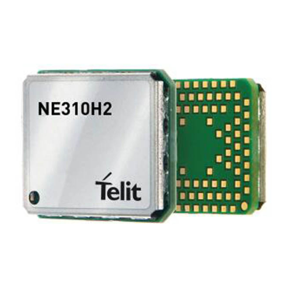
- Page 1 NE310H2 Hardware Design Guide 1VV0301608 Rev. 10 – 2020-08-12 Mod.0818 2017-01 Rev.0...
-
Page 2: Notice
NE310H2 Hardware Design Guide SPECIFICATIONS ARE SUBJECT TO CHANGE WITHOUT NOTICE NOTICE While reasonable efforts have been made to assure the accuracy of this document, Telit assumes no liability resulting from any inaccuracies or omissions in this document, or from use of the information obtained herein. -
Page 3: Usage And Disclosure Restrictions
NE310H2 Hardware Design Guide USAGE AND DISCLOSURE RESTRICTIONS License Agreements The software described in this document is the property of Telit and its licensors. It is furnished by express license agreement only and may be used only in accordance with the terms of such an agreement. -
Page 4: Applicability Table
NE310H2 Hardware Design Guide APPLICABILITY TABLE PRODUCTS NE310H2-W1 1VV0301608 Rev 10 Page 4 of 75 2020-08-12... -
Page 5: Table Of Contents
NE310H2 Hardware Design Guide Contents NOTICE COPYRIGHTS ....................2 COMPUTER SOFTWARE COPYRIGHTS ............2 USAGE AND DISCLOSURE RESTRICTIONS ..........3 License Agreements ..............3 Copyrighted Materials ..............3 III. High Risk Materials ............... 3 Trademarks .................. 3 Third Party Rights ................. 3 APPLICABILITY TABLE ................ - Page 6 NE310H2 Hardware Design Guide Operating Modes ................ 24 Power Supply Requirements ............25 Power Consumption ..............26 General Design Rules ..............28 4.4.1. Electrical Design Guidelines ............28 4.4.1.1. +5V/+12V Source Power Supply Design Guidelines ....28 4.4.1.2. Battery Source Power Supply Design Guidelines ......29 4.4.2.
- Page 7 NE310H2 Hardware Design Guide 6.1.1. Main Antenna ................57 6.1.2. PCB Design guidelines ............... 58 6.1.2.1. Transmission line design ............59 6.1.2.2. Transmission Line Measurements ..........60 6.1.2.3. Antenna Installation Guidelines ........... 61 MECHANICAL DESIGN ............. 62 APPLICATION PCB DESIGN ............ 63 PCB pad design ................
-
Page 8: Introduction
This document introduces the Telit NE310H2 modules and presents possible and recommended hardware solutions for developing a product based on this module. All the features and solutions detailed in this document are applicable to all NE310H2 variants, where NE310H2 refers to the variants listed in the applicability table. -
Page 9: Text Conventions
NE310H2 Hardware Design Guide Text Conventions Danger – This information MUST be followed or catastrophic equipment failure or bodily injury may occur. Caution or Warning – Alerts the user to important points about integrating the module, if these points are not followed, the module and end user equipment may fail or malfunction. -
Page 10: Related Documents
NE310H2 Hardware Design Guide Related Documents • AT Commands User Guide, 1VV0301611 • xE310 TLB Documentation, 1VV0301617 1VV0301608 Rev 10 Page 10 of 75 2020-08-12... -
Page 11: General Product Description
NE310H2 Hardware Design Guide 2. GENERAL PRODUCT DESCRIPTION Overview The NE310H2 is part of a new generation of modules in Telit’s NBIoT module portfolio. With its compact LGA footprint, it is designed for those m2m applications requiring miniature foot print. -
Page 12: Target Market
NE310H2 Hardware Design Guide Target market The NE310H2 enables enterprises to deploy new small footprint designs across many application areas including: • Utility metering • Home and commercial security • POS devices • Logistics terminals Main features Function Features •... -
Page 13: Rx Sensitivity
NE310H2 Hardware Design Guide RX Sensitivity Band REFsens (dBm)Typical 3GPP REFsens (dBm)* Band 1 -115.1 -108.2 Band 2 -115.1 -108.2 Band 3 -114.1 -108.2 Band 4 -114.9 Band 5 -115.3 -108.2 Band 8 -115.5 -108.2 Band 12 -115.2 -108.2 Band 13 -115.3... -
Page 14: Mechanical Specifications
NE310H2 Hardware Design Guide Mechanical specifications 2.7.1. Dimensions The overall dimensions of NE310H2 family are: Length: 15 mm Width: 18 mm Thickness: 2.3 mm Temperature Range Condition Range Note The module is fully functional(*) within this 3GPP temperature Operating Temperature Range -20°C to +55°C... -
Page 15: Pins Allocation
NE310H2 Hardware Design Guide 3. PINS ALLOCATION Pin-out Signal Function Type Comment Asynchronous Serial Port (USIF0) – Prog. / Data + HW Flow Control TXD0 Serial data input (TXD) from DTE CMOS 1.8 AA15 RXD0 Serial data output (RXD) to DTE CMOS 1.8... - Page 16 NE310H2 Hardware Design Guide SIM card interface SIM_CLK External SIM signal – Clock 1.8 V SIM_RST External SIM signal – Reset 1.8 V SIM_DAT External SIM signal – Data I/O 1.8 V External SIM signal – Power supply for the SIM_VCC 1.8 V...
- Page 17 NE310H2 Hardware Design Guide RF Section Main Antenna MAIN ANTENNA Main Antenna (50 ohm) (50 ohm) Miscellaneous Functions S_LED Status LED CMOS 1.8V ON_OFF* Input Command for Power ON/OFF CMOS 1.8V Active Low RST* Reset CMOS 1.8V Active Low WAKE* Input Command to Wake from PSM CMOS 1.8V...
- Page 18 NE310H2 Hardware Design Guide Power Supply Range: 3.0~3.6 V, VBATT_PA Main power supply (Radio PA) recommended Power value is 3.3V Range: 3.0~3.6 V, VBATT Main power supply (Baseband) recommended Power value is 3.3V RF Ground Power RF Ground Power RF Ground...
- Page 19 NE310H2 Hardware Design Guide Thermal Ground Power Thermal Ground Power Thermal Ground Power Thermal Ground Power Thermal Ground Power Thermal Ground Power Thermal Ground Power Thermal Ground Power Thermal Ground Power Thermal Ground Power Power Ground Power Power Ground Power...
- Page 20 NE310H2 Hardware Design Guide RESERVED RESERVED RESERVED RESERVED RESERVED RESERVED RESERVED RESERVED RESERVED RESERVED RESERVED RESERVED RESERVED RESERVED RESERVED RESERVED AA13 RESERVED RESERVED RESERVED RESERVED RESERVED RESERVED RESERVED RESERVED RESERVED RESERVED RESERVED RESERVED RESERVED RESERVED RESERVED RESERVED WARNING Reserved pins must not be connected.
- Page 21 NE310H2 Hardware Design Guide If not used, almost all pins should be left disconnected. The only exceptions are the following pins: Signal Note VBATT_PA VBATT A3, A7, A9, A13, A17, B4, B6, B10, B12, B14, B16, C19, D18, F8, F12, F18, G19, H6,...
- Page 22 NE310H2 Hardware Design Guide USB_D- On TP or a Connector USB_VBUS On TP or a Connector RTS pin should be connected to the GND (on the module side) if flow control is not used. The above pins are also necessary to debug the application when the module is assembled on it so we recommend connecting them also to dedicated test point.
-
Page 23: Lga Pads Layout
NE310H2 Hardware Design Guide LGA Pads Layout TOP VIEW 1VV0301608 Rev 10 Page 23 of 75 2020-08-12... -
Page 24: Power Supply
NE310H2 Hardware Design Guide 4. POWER SUPPLY The power supply circuitry and board layout are a very important part in the full product design and they strongly reflect on the product overall performances, hence read carefully the requirements and the guidelines that will follow for a proper design. -
Page 25: Power Supply Requirements
NE310H2 Hardware Design Guide Power Supply Requirements The external power supply must be connected to VBATT & VBATT_PA signals and must fulfil the following requirements: Power Supply Value Nominal Supply Voltage 3.3V Operating Voltage Range 3.00 V÷ 3.60 V Extended Voltage Range 2.10 V÷... -
Page 26: Power Consumption
NE310H2 Hardware Design Guide Power Consumption Status Description Average Max. value Unit Shutdown Shutdown leakage current AT+CFUN=0 Turn off radio and SIM power PSM mode Power Save Mode IDLE Idle mode Band1,Pout=23dBm Band2,Pout=23dBm Band3,Pout=23dBm Band4,Pout=23dBm Band5,Pout=23dBm Band8,Pout=23dBm Band12,Pout=23dBm Operating current in Band13,Pout=23dBm... - Page 27 NE310H2 Hardware Design Guide Band66,Pout=23dBm Band71,Pout=23dBm Band85,Pout=23dBm 1VV0301608 Rev 10 Page 27 of 75 2020-08-12...
-
Page 28: General Design Rules
NE310H2 Hardware Design Guide General Design Rules The principal guidelines for the Power Supply Design embrace three different design steps: • the electrical design • the thermal design • the PCB layout. 4.4.1. Electrical Design Guidelines The electrical design of the power supply depends strongly from the power source where this power is drained. -
Page 29: Battery Source Power Supply Design Guidelines
The three cells Ni/Cd or Ni/MH 3.6 V Nom. Battery types or 4V PB types MUST NOT BE USED DIRECTLY since their maximum voltage can rise over the absolute maximum voltage for the NE310H2-W1 and damage it. NOTE: DON’T USE any Ni-Cd, Ni-MH, and Pb battery types directly connected with NE310H2-W1. -
Page 30: Thermal Design Guidelines
NE310H2 Hardware Design Guide 4.4.2. Thermal Design Guidelines The thermal design for the power supply heat sink should be done considering the values described in the “Power Consumption” chapter. Considering the very low current during idle, especially if Power Saving function is enabled, it is possible to consider from the thermal point of view that the device absorbs current significantly only during calls. -
Page 31: Power Supply Pcb Layout Guidelines
FBMH1608HM101 can be used for this purpose. RTC Bypass out The NE310H2 module is provided by an internal RTC section but its reference supply is VBATT. So, in order to maintain active the RTC programming, VBATT should not be removed... -
Page 32: Vaux Power Output
NE310H2 Hardware Design Guide VAUX Power Output A regulated power supply output is provided in order to supply small devices from the module. The signal is in common with the PWRMON (module powered ON indication) function. This output is always active when the module is powered ON. The operating... -
Page 33: Digital Section
NE310H2 Hardware Design Guide 5. DIGITAL SECTION Logic Levels ABSOLUTE MAXIMUM RATINGS: Parameter Input level on any digital pin (CMOS 1.8) with respect -0.3V 2.1V to ground OPERATING RANGE – INTERFACE LEVELS (1.8V CMOS): Parameter Input high level 1.35V 1.98V Input low level -0.3V... -
Page 34: Power On
NE310H2 Hardware Design Guide Power On To turn on the NE310H2-W1 the pad ON_OFF* must be tied low for at least 0.5 second and then released. This is the typical time sequence: VBATT ≥500ms ON_OFF* 42ms VAUX Default Bus BOOTING RUNNING The ON_OFF circuit design is divided into two types: 1.8V and non-1.8V in realation to the... - Page 35 NE310H2 Hardware Design Guide The non-1.8V ON_OFF reference circuit design is shown below: NOTE: To check if the device has powered on, the hardware line VAUX/PWRMON should be monitored. Do not directly connect this pin to GND through the resistor; otherwise, the module cannot enter the PSM mode.
- Page 36 NE310H2 Hardware Design Guide A flow chart showing the proper turn on procedure is displayed as follow: 1VV0301608 Rev 10 Page 36 of 75 2020-08-12...
- Page 37 NOTE: In order to avoid a back powering effect it is recommended to avoid having any HIGH logic level signal applied to the digital pins of the NE310H2-W1 when the module is powered off or during an ON/OFF transition 1VV0301608 Rev 10...
-
Page 38: Power Off
When the procedure is activated, the device issues a detach request to network informing that the device will not be reachable any more. To turn OFF the NE310H2-W1 the pad ON_OFF* must be tied low for at least 3 seconds (typical value 4s) and then released. - Page 39 NE310H2 Hardware Design Guide The following flow chart shows the proper turn off procedure: 1VV0301608 Rev 10 Page 39 of 75 2020-08-12...
-
Page 40: Unconditional Restart
NE310H2 Hardware Design Guide Unconditional Restart To unconditionally restart the NE310H2-W1, the pad RST* must be tied low for at least 400 millisecond sand then released. The hardware unconditional Restart must not be used during normal operation of the device since it does not detach the device from the network. It shall be kept as an emergency exit procedure to be done in the rare case that the device gets stuck waiting for some network or SIM responses. -
Page 41: Operating Levels
NE310H2 Hardware Design Guide 5.4.2. Operating levels The RST* line is connected to VBATT with a Pull Up so the electrical levels on this pin are aligned to the main supply level. WARNING: The hardware unconditional Reset must not be used during normal operation of the device since it does not detach the device from the network. -
Page 42: Wakeup From Psm
NOTE: In order to avoid a back powering effect it is recommended to avoid having any HIGH logic level signal applied to the digital pins of the NE310H2-W1 when the module is powered off or during a reboot transition. NOTE: To proper power on again the module please refer to the related paragraph (“Power ON”) - Page 43 NE310H2 Hardware Design Guide The WAKE from PSM process is described in the following flowchart: “Modem Wake Proc” START VBATT>3V? PWMRON = ON? WAKE * =Low GOTO “HW SHUTDOWN Delay = 4 ms unconditional” WAKE*=High PWMRON = ON? Delay 1s GOTO “Start AT CMD.”...
-
Page 44: Application Example
NE310H2 Hardware Design Guide 5.1.2. Application Example WAKE circuit design is divided into two types:1.8V and non-1.8V. The 1.8V WAKE* reference circuit design is shown below. The resistance value is for reference only. Please fine tune it according to the specific application design: The non-1.8V WAKE* reference circuit design is the following:... -
Page 45: Spi
NE310H2 Hardware Design Guide The module is supporting one SPI port (Master Only). The signals are available on the following pads: Name Descriprtion Type Notes SPI_CS SPI - Circuit Select CMOS 1.8V SPI_CLK SPI - Clock CMOS 1.8V SPI_MOSI SPI - MOSI CMOS 1.8V... -
Page 46: Communication Ports
On the NE310H2 the ports are CMOS 1.8. 5.3.1.1. MODEM SERIAL PORT 0 (USIF0) The main serial port on the NE310H2 is a +1.8V UART with two flow control signals (CTS, RTS). It differs from the PC-RS232 in the signal polarity (RS232 is reversed) and levels. - Page 47 NOTE: In order to avoid a back powering effect it is recommended to avoid having any HIGH logic level signal applied to the digital pins of the NE310H2-W1 when the module is powered off or during a reboot transition. 1VV0301608 Rev 10...
-
Page 48: Modem Serial Port 1 (Usif1)
NE310H2 Hardware Design Guide 5.3.1.2. MODEM SERIAL PORT 1 (USIF1) The secondary serial port on the NE310H2 is a +1.8V UART It differs from the PC-RS232 in the signal polarity (RS232 is reversed) and levels. The following table is listing the available signals:... -
Page 49: Modem Serial Port 3 (Auxiliary - Debug Only)
C104/RXD1) In order to avoid a back powering effect it is recommended to avoid having any HIGH logic level signal applied to the digital pins of the NE310H2 when the module is powered off or during a reboot transition. -
Page 50: Rs232 Level Translation
NE310H2 Hardware Design Guide 5.3.1.4. RS232 LEVEL TRANSLATION In order to interface the module with a PC com port or a RS232 (EIA/TIA-232) application a level translator is required. This level translator must: • invert the electrical signal in both directions;... - Page 51 NE310H2 Hardware Design Guide Second solution could be done using a MAXIM transceiver TXS0104E. In this case, there is no need to use a single chip level translator. NOTE: In this case has to be taken in account the length of the lines on the application to avoid problems in case of High-speed rates on RS232.
-
Page 52: V/5V Uart Level Translation
NE310H2 Hardware Design Guide 5.3.1.5. 3.3V/5V UART level translation If the OEM application uses a microcontroller with a serial port (UART) that works at a voltage different from 1.8V, then a circuitry has to be provided to adapt the different levels of the two set of signals. -
Page 53: General Purpose I/O
NE310H2 Hardware Design Guide General purpose I/O The NE310H2-W1 module is provided by a set of Configurable Digital Input / Output pins (CMOS 1.8) Input pads can only be read; they report the digital value (high or low) present on the pad at the read time. -
Page 54: Using A Gpio As Input
NOTE: In order to avoid a back powering effect it is recommended to avoid having any HIGH logic level signal applied to the digital pins of the NE310H2-W1 when the module is powered off or during a reboot transition. The VAUX pin can be used for input pull up reference or/and for ON monitoring. -
Page 55: Indication Of Network Service Availability
The SLED (B2) pin status shows information on the network service availability and Call status. In the NE310H2-W1 modules, the SLED needs an external transistor to drive an external LED. Therefore, the status indicated in the following table is reversed with respect to the pin status. -
Page 56: External Sim Holder
NE310H2 Hardware Design Guide External SIM Holder SIM circuit reference design is as in the following schematic: The minimum value of Capacitor on SIMVCC is 1μF. The module provides one ADC to digitize the analog signal to 10-bit digital data such as battery voltage, temperature and so on. -
Page 57: Rf Section
The antenna and antenna transmission line on PCB for a Telit NE310H2-W1 device shall fulfill the following requirements:... -
Page 58: Pcb Design Guidelines
NE310H2-W1 antenna pad by means of a transmission line implemented on the PCB. In the case the antenna is not directly connected at the antenna pad of the NE310H2-W1, then a PCB line is needed in order to connect with it or with its connector. -
Page 59: Transmission Line Design
NE310H2 Hardware Design Guide • If you don’t have EM noisy devices around the PCB of NE310H2-W1, by using a micro strip on the superficial copper layer for the antenna line, the line attenuation will be lower than a buried one. -
Page 60: Transmission Line Measurements
NE310H2 Hardware Design Guide 6.1.2.2. Transmission Line Measurements An HP8753E VNA (Full-2-port calibration) has been used in this measurement session. A calibrated coaxial cable has been soldered at the pad corresponding to RF output; a SMA connector has been soldered to the board in order to characterize the losses of the transmission line including the connector itself. -
Page 61: Antenna Installation Guidelines
NE310H2 Hardware Design Guide Insertion Loss of G-CPW line plus SMA connector is shown below: 6.1.2.3. Antenna Installation Guidelines • Install the antenna in a place covered by the LTE signal. • The Antenna must be installed to provide a separation distance of at least 20 cm from all persons and must not be co-located or operating in conjunction with any other antenna or transmitter;... -
Page 62: Mechanical Design
NE310H2 Hardware Design Guide 7. MECHANICAL DESIGN NOTE: The dimensions are in mm 1VV0301608 Rev 10 Page 62 of 75 2020-08-12... -
Page 63: Application Pcb Design
SMT process. Units: mm In order to easily rework the NE310H2 is suggested to consider on the application a 1.5 mm placement inhibit area around the module. It is also suggested, as common rule for an SMT component, to avoid having a mechanical part of the application in direct contact with the module. -
Page 64: Pcb Pad Design
NE310H2 Hardware Design Guide PCB pad design Non solder mask defined (NSMD) type is recommended for the solder pads on the PCB. Copper Pad Solder Mask NSMD (Solder Mask Defined) (Non Solder Mask Defined) PCB pads It is not recommended to place via or micro-via not covered by solder resist in an area of 0,3 mm around the pads unless it carries the same signal of the pad itself. -
Page 65: Stencil
Solder Paste Sn/Ag/Cu We recommend using only “no clean” solder paste in order to avoid the cleaning of the modules after assembly. Solder Reflow WARNING: THE NE310H2 MODULE WITHSTANDS ONE REFLOW PROCESS ONLY. 1VV0301608 Rev 10 Page 65 of 75 2020-08-12... -
Page 66: Packaging
NE310H2 Hardware Design Guide 9. PACKAGING Tray The NE310H2 modules are packaged on trays. These trays can be used in SMT processes for pick & place handling. 1VV0301608 Rev 10 Page 66 of 75 2020-08-12... - Page 67 NE310H2 Hardware Design Guide 1VV0301608 Rev 10 Page 67 of 75 2020-08-12...
-
Page 68: Moisture Sensitivity
NE310H2 Hardware Design Guide Moisture sensitivity The NE310H2 is a Moisture Sensitive Device level 3, in according with standard IPC/JEDEC J-STD-020, take care all the relatives requirements for using this kind of components. Moreover, the customer has to take care of the following conditions: a) Calculated shelf life in sealed bag: 12 months at <40°C and <90% relative humidity... -
Page 69: Conformity Assessment Issues
NE310H2 Hardware Design Guide CONFORMITY ASSESSMENT ISSUES Approvals RoHS and REACH Declaration of Conformity The DoC will be available here: https://www.telit.com/RED/ 1VV0301608 Rev 10 Page 69 of 75 2020-08-12... -
Page 70: Safety Recommendations
NE310H2 Hardware Design Guide SAFETY RECOMMENDATIONS READ CAREFULLY Be sure the use of this product is allowed in the country and in the environment required. The use of this product may be dangerous and has to be avoided in the following areas: •... -
Page 71: Reference Table Of Rf Bands Characteristics
NE310H2 Hardware Design Guide REFERENCE TABLE OF RF BANDS CHARACTERISTICS Band Freq. Tx (MHz) Freq. Rx (MHz) 1920 MHz – 1980 MHz 2110 MHz – 2170 MHz 1850 MHz – 1910 MHz 1930 MHz – 1990 MHz 1710 MHz – 1785 MHz 1805 MHz –... -
Page 72: Acronyms
NE310H2 Hardware Design Guide ACRONYMS TTSC Telit Technical Support Centre Universal Serial Bus High Speed Data Terminal Equipment UMTS Universal Mobile Telecommunication System WCDMA Wideband Code Division Multiple Access HSDPA High Speed Downlink Packet Access HSUPA High Speed Uplink Packet Access... - Page 73 NE310H2 Hardware Design Guide Master Input – Slave Output MISO Clock MRDY Master Ready SRDY Slave Ready Chip Select Real Time Clock Printed Circuit Board Equivalent Series Resistance VSWR Voltage Standing Wave Radio Vector Network Analyzer TTFF Time to First Fix...
-
Page 74: Document History
NE310H2 Hardware Design Guide DOCUMENT HISTORY Revision Date Changes First emission – Preliminary 2019-06-26 2019-08-14 Updated overall document 2019-08-20 Updated 5.3, 5.3.1.3 chapters Updated chapters 2.1, 2.3, 2.4, 9, 10.2 2019-08-30 Updated mechanical dimensions Added Temperature range 2019-09-30 Updated Chapter 3.1, 4.1, 4.2, 5.1, 6.1.1 2019-10-10 Updated Chapter 2.2, 4.1... - Page 75 Mod.0818 2017-01 Rev.0...
Need help?
Do you have a question about the NE310H2 and is the answer not in the manual?
Questions and answers