
Related Manuals for Keysight Technologies J7204A


Summary of Contents for Keysight Technologies J7204A
- Page 1 Keysight Multi-Channel Attenuation Control Unit: J7204A 4-channel, DC to 6 GHz J7204B 4-channel, DC to 18 GHz J7205A 5-channel, DC to 6 GHz J7205B 5-channel, DC to 18 GHz Operating and Service Manual...
- Page 2 Federal Acqui- DOCUMENT IS PROVIDED “AS IS,” sition Regulation (“FAR”) 2.101. Pursu- AND IS SUBJECT TO BEING © Keysight Technologies 2015 ant to FAR 12.212 and 27.405-3 and CHANGED, WITHOUT NOTICE, IN No part of this manual may be repro- Department of Defense FAR Supple- FUTURE EDITIONS.
-
Page 3: Safety Symbols
Safety Symbols The following symbols on the instrument and in the documentation indicate precautions which must be taken to maintain safe operation of the instrument. Caution, risk of danger (refer to this Power line switch is in the STANDBY manual for specific Warning or Caution position information) Frame or chassis (ground) terminal... -
Page 4: Safety Considerations
Safety Considerations Read the information below before using this instrument. The following general safety precautions must be observed during all phases of operation, service, and repair of this instrument. Failure to comply with these precautions or with specific warnings elsewhere in this manual violates safety standards for design, manufacture, and intended use of the instrument. - Page 5 – Danger of explosion if battery is incorrectly replaced. Replace only with WARNING the same or equivalent type recommended. Discard used batteries according to manufacturer’s instructions. – For continued protection against fire hazard, replace the line fuse only with the same type and rating. The use of other fuses or material is prohibited.
-
Page 6: Regulatory Information
Regulatory Information Statement of compliance This instrument has been designed and tested in accordance with CAN/CSA-C22.2 No. 61010-1-12, UL Std. No. 61010-1 (3rd Edition). Regulatory markings The CE mark is a registered trademark of the European Community. This CE The CSA mark is a registered mark shows that the product complies trademark of the Canadian with all the relevant European Legal... -
Page 7: Waste Electrical And Electronic Equipment (Weee) Directive 2002/96/ Ec
Waste Electrical and Electronic Equipment (WEEE) Directive 2002/ 96/EC This instrument complies with the WEEE Directive (2002/96/EC) marking requirement. This affixed product label indicates that you must not discard this electrical or electronic product in domestic household waste. Product category: With reference to the equipment types in the WEEE directive Annex 1, this instrument is classified as a “Monitoring and Control Instrument”... - Page 8 THIS PAGE HAS BEEN INTENTIONALLY LEFT BLANK. Keysight J7204/5/A/B Operating and Service Manual...
-
Page 9: Table Of Contents
Table of Contents Safety Symbols ..........3 Safety Considerations . - Page 10 General Specifications ........30 Specifications .
- Page 11 ......20 Figure 3-1 Mechanical dimensions of the J7204A/B with Type-N connector ....... . .33...
- Page 12 THIS PAGE HAS BEEN INTENTIONALLY LEFT BLANK. Keysight J7204/5/A/B Operating and Service Manual...
- Page 13 List of Tables Table 1-1 J7204/5/A/B connector options ....17 Table 1-2 J7204/5/A/B’s state LED definitions ....19 Table 2-1 J7204/5/A/B shipment contents .
- Page 14 THIS PAGE HAS BEEN INTENTIONALLY LEFT BLANK. Keysight J7204/5/A/B Operating and Service Manual...
- Page 15 Keysight J7204/5/A/B Attenuation Control Unit Operating and Service Manual Introduction Product Overview This chapter provides an overview of the Keysight J7204/5/A/B Multi-Channel Attenuation Control Unit.
-
Page 16: Introduction
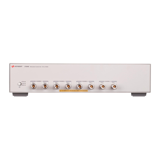
The J7204/5/A/B attenuation control unit is made up of a 2U, full-rack chassis. The J7204A/B is equipped with four sets of 11 dB/110 dB attenuator pairs while the J7205A/B is equipped with five sets of 11 dB/110 dB attenuator pairs, with a DC to 6 GHz/18 GHz frequency range. -
Page 17: Key Features Of The J7204/5/A/B Attenuation Control Unit
– LAN and GPIB interfaces with soft front panel provide easy connectivity, programming flexibility, and control Instrument options There are two connector options available for the J7204/5/A/B as follows: Table 1-1 J7204/5/A/B connector options Option number Description J7204A-001 Type-N connector J7204A-002 SMA connector J7204B-001 Type-N connector J7204B-002 SMA connector... -
Page 18: Front And Rear Panel Features
J7204/5/A/B’s states based on the color and functionality of the LEDs. – For J7204A/B: There are four channels, with two ports per channel: Port 1 and Port 2. Each channel has one input port and one output port. The front panel RF connector is either SMA (female) or Type-N. -
Page 19: Table 1-1 Table
Introduction Table 1-2 J7204/5/A/B’s state LED definitions Color Instrument state ATTN Instrument in the “ready” state Green LAN connection established Green – instrument has an IP address firmware download complete ATTN flashing Power-on/boot-up. ATTN and LAN will flash red and then green flashing during the power-on self-test. -
Page 20: Figure 1-3 J7204/5/A/B Rear Panel
Introduction Rear panel Line input GPIB connector Figure 1-3 J7204/5/A/B rear panel GPIB connector This connector allows the J7204/5/A/B to be connected directly to a controller. The J7204/5/A/B is controlled over the Local Area Network (LAN). The line input contains the power cord receptacle. Install the J7204/5/A/B so that the detachable power cord is readily identifiable and is easily reached. - Page 21 Keysight J7204/5/A/B Attenuation Control Unit Operating and Service Manual Installation Initial Inspection Verify the J7204/5/A/B Shipment Contents Service and Recalibration Related Documentation System Requirements Software Installation Operating and Safety Precautions This chapter provides you important information on how to check and prepare your instrument for operation.
-
Page 22: Installation
“Sales and Technical Support” on page 7 of this manual for the Keysight Technologies nearest to you. Attach a tag indicating the type of service required, return address, model number, and serial number. Mark the container FRAGILE to insure careful handling. In any correspondence, refer to the instrument by model number and serial number. -
Page 23: Verify The J7204/5/A/B Shipment Contents
Installation Verify the J7204/5/A/B Shipment Contents The following table lists the items that are shipped with the J7204/5/A/B. Table 2-1 J7204/5/A/B shipment contents Quantity Description Part number Certificate of Calibration 5962-0476 CD-ROM, IO Libraries Media Suite E2094-60003 English, Product Software and Information CD, CD-ROM J7205-10002 J7205-10003 CD-ROM —... -
Page 24: System Requirements
Installation System Requirements Prior to any installation or configuration, ensure that the following system requirements are met. Windows 7 (32-bit and 64-bit) Starter, Home Basic, Home Premium, Operating system Professional, Ultimate, Enterprise 1 GHz 32-bit (x86), Processor speed 1 GHz 64-bit (x64), no support for Itanium 64 Available memory 1 GB minimum... -
Page 25: Software Installation
Installation Software Installation The J7204/5/A/B software is located on the J720xA/B Product Software and Information CD (J7205-10002). This software is also available for download at www.keysight.com/find/attenuators. The Keysight IO Libraries Suite (which includes the Keysight Connection Expert) is located on the Keysight IO Libraries Suite CD (E2094-60003). The software installation includes the following items: –... -
Page 26: Operating And Safety Precautions
Installation Operating and Safety Precautions Observe the following guidelines before connecting or operating the J7204/5/A/B attenuation control unit. For further safety information, refer to “Safety Considerations” on page 4. ESD damage Protection against electrostatic discharge (ESD) is important while handling and operating the J7204/5/A/B. - Page 27 Installation – Gage connectors periodically. This not only provides assurance of proper mechanical tolerances and thus connector performance, but can also indicate situations where the potential for damage to another connector may exist. The J7204/5/A/B can be damaged if excessive torque is applied to the CAUTION connectors.
- Page 28 Installation THIS PAGE HAS BEEN INTENTIONALLY LEFT BLANK. Keysight J7204/5/A/B Operating and Service Manual...
-
Page 29: Specifications
Keysight J7204/5/A/B Attenuation Control Unit Operating and Service Manual Specifications General Specifications Mechanical Dimensions Environmental Specifications This chapter provides the specifications of the J7204/5/A/B Attenuation Control Unit. -
Page 30: General Specifications
Specifications General Specifications The J7204/5/A/B’s performance is specified for a standalone instrument. NOTE The J7204/5/A/B has an autoranging line voltage input. Be sure the supply CAUTION voltage is within the specified range. Specifications Specifications refer to the performance standards or limits against which the J7204/5/A/B is tested. -
Page 31: Power Requirements
Specifications Table 3-2 Attenuation accuracy of the J7204/5/A/B Attenuation setting for step range (dB) DC to 6 GHz 6 to 18 GHz 1 to 2 3 to 4 5 to 6 7 to 10 11 to 20 21 to 40 41 to 60 61 to 80 81 to 100... -
Page 32: Physical Specifications
Specifications Physical specifications Table 3-3 Physical specifications of the J7204/5/A/B Specifications J7204A J7204B J7205A J7205B Net weight 11 kg 11 kg 11.5 kg 11.5 kg Shipping weight 17 kg 17 kg 17.5 kg 17.5 kg Shipping dimensions: Length 770 mm... -
Page 33: Mechanical Dimensions
Specifications Mechanical Dimensions Figure 3-1 Mechanical dimensions of the J7204A/B with Type-N connector Keysight J7204/5/A/B Operating and Service Manual... -
Page 34: Figure 3-2 Mechanical Dimensions Of The J7204A/B With Sma
Specifications Figure 3-2 Mechanical dimensions of the J7204A/B with SMA connector Keysight J7204/5/A/B Operating and Service Manual... -
Page 35: Figure 3-3 Mechanical Dimensions Of The J7205A/B With Type-N Connector
Specifications Figure 3-3 Mechanical dimensions of the J7205A/B with Type-N connector Keysight J7204/5/A/B Operating and Service Manual... -
Page 36: Figure 3-4 Mechanical Dimensions Of The J7205A/B With Sma Connector
Specifications Figure 3-4 Mechanical dimensions of the J7205A/B with SMA connector Keysight J7204/5/A/B Operating and Service Manual... -
Page 37: Environmental Specifications
Specifications Environmental Specifications The J7204/5/A/B is designed to fully comply with Keysight Technologies's product operating environment specifications. The following table shows the summarized environmental specifications for this product. Table 3-4 J7204/5/A/B environmental specifications Temperature 0 to +55 °C – Operating –40 °C to +70 °C... - Page 38 Specifications THIS PAGE HAS BEEN INTENTIONALLY LEFT BLANK. Keysight J7204/5/A/B Operating and Service Manual...
- Page 39 Keysight J7204/5/A/B Attenuation Control Unit Operating and Service Manual Operating Guide Operating Instructions Getting Started with the Soft Front Panel (SFP) Controlling the J7204/5/A/B Attenuation Control Unit Programming Guide Service and Maintenance This chapter provides simple quick-check instructions to verify the J7204/5/A/B attenuation control unit’s functionality prior to usage.
-
Page 40: Operating Guide
Operating Guide Operating Instructions Operator’s check The operator’s check is supplied to allow the operator to make a quick check of the J7204/5/A/B prior to usage or if a failure is suspected. ESD exceeding the level specified in Table 3-4 or the RF power applied is CAUTION greater than the maximum specified as in... - Page 41 Operating Guide Quick-check procedure 1 Set the following parameters on the network analyzer to perform 2-port measurements: Parameter J7204A / J7205A J7204B / J7205B Start frequency 200 MHz 200 MHz Stop frequency 6 GHz 18 GHz IF bandwidth 100 Hz...
-
Page 42: Figure 4-2 Setting The Attenuation Value
Operating Guide Figure 4-2 Setting the attenuation value Keysight J7204/5/A/B Operating and Service Manual... -
Page 43: Getting Started With The Soft Front Panel (Sfp)
Operating Guide Getting Started with the Soft Front Panel (SFP) This section guides you through the SFP that provides an easy-to-use interface for controlling the J7204/5/A/B. 1 Refer to Chapter 2, "Software Installation" to install the SFP. 2 Launch the SFP software from the desktop by double-clicking the SFP icon, or from Start >... -
Page 44: Figure 4-4 J7205X Main Sfp Interface
Operating Guide Figure 4-4 J7205x main SFP interface Table 4-1 Overview of the main SFP interface Item Description – The File menu consists of the following functions: – Connect: Opens the Connect To Instrument window. This window also appears when you launch the SFP. –... - Page 45 Operating Guide Table 4-1 Overview of the main SFP interface No. Item Description Controls the attenuation for each channel via fixed step sizes or direct numeric input Attenuator control of the attenuation value. Status indicator Displays the connection string address and operating status of the unit. 5 The J7204/5/A/B SFP is a graphical interface that helps you with the following tasks: a To connect to the J7204/5/A/B via the GPIB interface...
-
Page 46: Figure 4-5 J7204/5/A/B Main Sfp Interface
Operating Guide -- Click Connect to access the main interface of the selected J7204x or J7205x unit. -- To select another unit to use when accessing the main interface, click File > Connect from the menu bar to open the Connect To Instrument window. c To operate the J7204/5/A/B -- On the J7204/5/A/B main SFP interface as shown in Figure... -
Page 47: Figure 4-6 Errors Window
Operating Guide e To view error cond itions -- On the main SFP interface as shown in Figure 4-5, click Utility > Error from the menu bar to open the Errors window as shown in Figure 4-6. Figure 4-6 Errors window -- Click Get Errors to display the list of errors that occurred when using the SFP. -
Page 48: Figure 4-7 Driver Log Window
Operating Guide Figure 4-7 Driver Log window -- To save the driver call log to a file, click File > Save As. – To select all the driver calls in the log, click Ed it > Select All. – To copy a selected driver call to your application, click Ed it > Copy. -- To erase all the driver calls from the log, click Clear Log. -
Page 49: Controlling The J7204/5/A/B Attenuation Control Unit
Operating Guide Controlling the J7204/5/A/B Attenuation Control Unit Controlling the J7204/5/A/B and making measurements The J7204/5/A/B attenuation control unit is a “slave” instrument. A controller must be used to control the J7204/5/A/B. There are two methods that can be used to control the J7204/5/A/B. –... -
Page 50: Figure 4-8 Add Lan Instrument
Operating Guide Figure 4-8 Add LAN instrument 5 The J7204/5/A/B is now added as shown in Figure 4-9 on page 51. Keysight J7204/5/A/B Operating and Service Manual... -
Page 51: Figure 4-9 Lan Instrument Added
Operating Guide Figure 4-9 LAN instrument added The Keysight Connection Expert window will display the L4490A as the NOTE J7204/5/A/B is made up of the L4490-styled standard Keysight chassis. Keysight J7204/5/A/B Operating and Service Manual... -
Page 52: Gpib Connection
Operating Guide GPIB connection Programming access to the J7204/5/A/B is also available via its GPIB interface. The GPIB connector is located at the rear panel of the J7204/5/A/B. 1 Run the Keysight Connection Expert from the desktop icon, or from Start > All Programs >... -
Page 53: Programming Guide
Operating Guide Programming Guide SCPI command syntax The following conventions are used for SCPI command syntax for remote interface programming. – Square brackets ([]) indicate optional keywords or parameters. – Braces ({}) enclose parameter choices within a command string. – Angle brackets (<>) enclose parameters for which you must specify a value. –... - Page 54 Operating Guide Example a If you want an 8 dB attenuation at Channel 3: Execute the command ROUT:SEQ:TRIG ATTEN_3_1_8 b If you want a 75 dB attenuation at Channel 5: Execute the command ROUT:SEQ:TRIG ATTEN_5_1_5 and ATTEN 5_2_70 To query the attenuation level The following query is used to obtain the attenuation level of the J7204/5/A/B.
- Page 55 Operating Guide Attenuation (dB) Channel Section list 0 (Atten) 1 (Thru) 1121 1122 1123 1124 1125 1126 1127 1128 1141 1142 1143 1144 1145 1146 1147 1148 1161 1162 1163 1164 1165 1166 1167 1168 Keysight J7204/5/A/B Operating and Service Manual...
- Page 56 Operating Guide Attenuation (dB) Channel Section list 0 (Atten) 1 (Thru) 2125 2121 2122 2120 2116 2112 2113 2111 Example If you want to query the attenuation level for Channel 5: Execute the command ROUT:CLOS? (@2125,2121,2122,2120,2116,2112,2113,2111) The example returned value is 0,1,0,0,1,1,0,1 The attenuation level of 49 dB for Channel 5 is listed as follows: Channel Section list...
- Page 57 Operating Guide To query the cycle count The following query is used to obtain the cycle count of the J7204/5/A/B. Syntax DIAGnostic:RELay:CYCLes? (@<sec_list>) Parameter The following table provides the section list for each channel of the J7204/5/A/B. Attenuation (dB) Channel Section list 0 (Atten) 1 (Thru)
- Page 58 Operating Guide Attenuation (dB) Channel Section list 0 (Atten) 1 (Thru) 1141 1142 1143 1144 1145 1146 1147 1148 1161 1162 1163 1164 1165 1166 1167 1168 2125 2121 2122 2120 2116 2112 2113 2111 This query is not applicable for Channel 5. NOTE Keysight J7204/5/A/B Operating and Service Manual...
- Page 59 Operating Guide To clear cycle count The following command is used to clear cycle count of the J7204/5/A/B. Syntax DIAGnostic:RELay:CYCLes:CLEar (@<sec_list>) Parameter The following table provides the section list for each channel of the J7204/5/A/B. Attenuation (dB) Channel Section list 0 (Atten) 1 (Thru) 1101...
- Page 60 Operating Guide Attenuation (dB) Channel Section list 0 (Atten) 1 (Thru) 1141 1142 1143 1144 1145 1146 1147 1148 1161 1162 1163 1164 1165 1166 1167 1168 2125 2121 2122 2120 2116 2112 2113 2111 This command is not applicable for Channel 5. NOTE Keysight J7204/5/A/B Operating and Service Manual...
-
Page 61: J7204/5/A/B Scpi Commands
Operating Guide J7204/5/A/B SCPI commands The following table lists the SCPI commands that apply to the J7204/5/A/B. Table 4-2 J7204/5/A/B SCPI commands Subsystem Command *CLS *ESE <enable_value> *ESE? *ESR? *IDN? *OPC *OPC? IEEE-488 commands *RST *SRE <enable_value> *SRE? *STB? *TRG *TST? *WAI Keysight J7204/5/A/B Operating and Service Manual... -
Page 62: J7204/5/A/B Scpi Commands
Operating Guide Table 4-2 J7204/5/A/B SCPI commands (continued) Subsystem Command SYSTem:COMMunicate:GPIB:ADDRess <address> SYSTem:COMMunicate:GPIB:ADDRess? SYSTem:COMMunicate:LAN:AUTOip {OFF|0|ON|1} SYSTem:COMMunicate:LAN:AUTOip? SYSTem:COMMunicate:LAN:DHCP {OFF|0|ON|1} SYSTem:COMMunicate:LAN:DHCP? SYSTem:COMMunicate:LAN:DNS "<address>" System-related commands SYSTem:COMMunicate:LAN:DNS? SYSTem:COMMunicate:LAN:DOMain "<name>" SYSTem:COMMunicate:LAN:DOMain? [{CURRent|STATic}] SYSTem:COMMunicate:LAN:GATEway <address> SYSTem:COMMunicate:LAN:GATEway? [{CURRent|STATic}] SYSTem:COMMunicate:LAN:HOSTname? [{CURRent|STATic}] SYSTem:COMMunicate:LAN:IPADdress "<address>" SYSTem:COMMunicate:LAN:IPADdress? [{CURRent|STATic}] Keysight J7204/5/A/B Operating and Service Manual... -
Page 63: Service And Maintenance
Operating Guide Service and Maintenance Service The J7204/5/A/B does not have internal adjustments and should not be opened; it should only be repaired by service-trained personnel. Should it become necessary to return the J7204/5/A/B for repair or service, contact your nearest Keysight Sales and Service Center. - Page 64 Operating Guide THIS PAGE HAS BEEN INTENTIONALLY LEFT BLANK. Keysight J7204/5/A/B Operating and Service Manual...
- Page 65 This information is subject to change without notice. Always refer to the English version at the Keysight website for the latest revision. © Keysight Technologies 2015 Edition 1, Sept 17, 2015 Printed in Malaysia *J7205-90002* J7205-90002 www.keysight.com...
Need help?
Do you have a question about the J7204A and is the answer not in the manual?
Questions and answers