Table of Contents
Advertisement
Quick Links
Instructions - Parts List
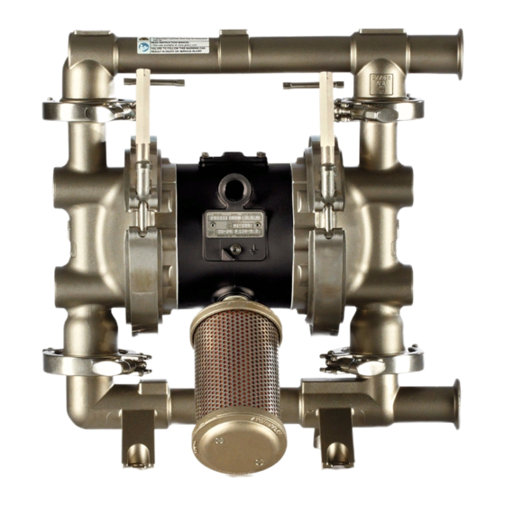
SaniForce
Diaphragm Pumps
1040 Models, Tested with Water
For use in sanitary applications. For professional use only.
Important Safety Instructions
Read all warnings and instructions in this
manual. Save these instructions.
120 psi (0.8 MPa, 8 bar) Maximum Fluid Working Pressure
120 psi (0.8 MPa, 8 bar) Maximum Air Input Pressure
™
Refer to the Pump Matrix on page 26 to determine the
model number of your pump. See page 3 for approval
information.
3A4238B
EN
TI8924a
Advertisement
Table of Contents

Related Manuals for Graco SaniForce FW1111


Summary of Contents for Graco SaniForce FW1111
- Page 1 Instructions - Parts List ™ SaniForce Diaphragm Pumps 3A4238B 1040 Models, Tested with Water For use in sanitary applications. For professional use only. Refer to the Pump Matrix on page 26 to determine the Important Safety Instructions model number of your pump. See page 3 for approval Read all warnings and instructions in this information.
-
Page 2: Table Of Contents
Maintenance ......13 Graco Warranties ......34 Troubleshooting . -
Page 3: Models
Models Models Model Connections Description Approvals *FW1___ Flange 1040 AODD Pump II 2 G *FW7___ *FW1111 Flange 1040 AODD Pump II 2 G *FW7111 * FW pumps have painted aluminum center sections that may exhibit signs of corrosion depending on cleaning solutions used. - Page 4 3. SaniForce 1590, 3150 HS 3-A Certified Air-Operated Double Diaphragm Pumps 4. SaniForce 5:1, 6:1 and 12:1 Air-Operated Piston Pumps 5. SaniForce Diaphragm Pump and Piston Pump Drum Unloaders 6. SaniForce Diaphragm Pump and Piston Pump Bin Evacuation Systems Bradley A. Byron Quality Manager Graco Inc. 3A4238B...
-
Page 5: Warnings
Warnings Warnings The following warnings are for the setup, use, grounding, maintenance, and repair of this equipment. The exclamation point symbol alerts you to a general warning and the hazard symbol refers to procedure-specific risk. When these symbols appear in the body of this manual, refer back to these Warnings. Additional, product-specific warnings may be found throughout the body of this manual where applicable. - Page 6 Warnings WARNING EQUIPMENT MISUSE HAZARD Misuse can cause death or serious injury. • Do not operate the unit when fatigued or under the influence of drugs or alcohol. • Do not exceed the maximum working pressure or temperature rating of the lowest rated system component.
-
Page 7: Installation
• Always use genuine Graco parts and accessories. • Pump: Connect a ground wire and clamp as shown •... - Page 8 Installation Mountings NOTICE The pump exhaust air may contain contaminants. In the step below, do not connect the Ventilate to a remote area if the contaminants could quick-disconnect coupler (D) on the air hose to the affect your fluid supply. See Air Exhaust Ventilation mating fitting on the pump until you are ready to on page 11.
- Page 9 Installation Fluid Outlet Line 1. Use flexible grounded fluid hoses (L). 2. For best sealing results, use a standard tri-clamp or DIN style sanitary gasket of a flexible material such A fluid drain valve (J) is required to relieve pressure as EPDM, Buna-N, fluoroelastomer, or silicon in the hose if it is plugged.
- Page 10 Installation Changing the Orientation of the Fluid Inlet and Outlet Ports The pump is shipped with the ports facing the same direction. To reverse the orientation of the ports: 1. Remove the clamps holding the inlet and/or outlet manifold to the covers. 2.
- Page 11 Installation Air Exhaust Ventilation To provide a remote exhaust: 1. Remove the muffler (P) from the pump air exhaust port. Be sure the system is properly ventilated for your type of installation. When pumping flammable or 2. Install a grounded air exhaust hose (T) and connect hazardous fluids, you must vent the exhaust to a the muffler (P) to the other end of the hose.
-
Page 12: Operation
Operation Operation Pressure Relief Procedure Starting and Adjusting the Pump 1. Be sure the pump is properly grounded. Refer to Grounding on page 7. 2. Check connections to be sure they are tight. Tighten fluid inlet and outlet connections securely. The equipment stays pressurized until pressure is manually relieved. -
Page 13: Maintenance
Maintenance Maintenance Lubrication Tightening Connections The air valve is designed to operate unlubricated, Before each use, check all hoses for wear or damage, however if lubrication is desired, every 500 hours of and replace as necessary. Check to be sure all operation (or monthly) remove the hose from the pump connections are tight and leak-free. -
Page 14: Troubleshooting
Troubleshooting Troubleshooting • Relieve the pressure before checking or servicing the equipment. • Check all possible problems and causes before dis- To reduce the risk of serious injury, whenever you assembling the pump. are instructed to relieve pressure, always follow the Pressure Relief Procedure on page 12. - Page 15 Troubleshooting PROBLEM CAUSE SOLUTION Leak in inlet or outlet sanitary fit- Loose sanitary clamp. Tighten clamp. ting. Damaged or worn gasket. Replace gasket. Misalignment of inlet/outlet hose or Use flexible hoses at pump inlet and pipe. outlet. Gasket does not seal. Use a standard sanitary gasket of flexible material such as EPDM, Buna-N, fluoroelastomer, or silicon.
-
Page 16: Service
Service Service Repairing the Air Valve Reassembly 1. If you replaced the bearings (12, 15), reinstall as Tool Required explained on page 24. Reassemble the fluid section. • Torque wrench • Torx (T20) screwdriver or 7 mm (9/32 in.) socket 2. - Page 17 Service Insert narrow end first Torque to 52-60 in-lb (5.6-6.8 • Grease Install with lips facing narrow end of piston (11) Insert wide end first TI9086A TI9089A Detail 1 Tighten screws until they bottom out on the housing. See detail at right.
- Page 18 Service Ball Check Valve Repair 1 Arrow (A) must point toward outlet manifold (103) Radiused seating surface must face the ball (301). Tools Required Large chamfer on O.D. must face o-ring. • O-ring pick Disassembly NOTE: • A Fluid Section Repair Kit is available. Refer to the Repair Kit Matrix parts section for the appropriate pump size so that the correct kit for your pump is ordered.
- Page 19 Service Standard Diaphragm Repair NOTE: If your pump uses overmolded diaphragms, see page 22. Tools Required • Torque wrench 1. Relieve the pressure. • 15 mm socket wrench • 19 mm open end wrench 2. Remove the manifolds and disassemble the ball •...
- Page 20 Service 4. Loosen but do not remove the diaphragm shaft bolts d. On PTFE models only, install the backer (401*) (107), using a 15 mm socket wrench on both bolts. on the bolt. Make certain the side marked AIR See F .
- Page 21 Service 402* Cutaway view, with diaphragms in place 403* 24 104 401* TI8935a 401* 403* 108* TI8934a Lips face out of housing (1). Rounded side faces diaphragm (401). Air side must face center housing (1). Grease. Apply medium strength (blue) thread locker. Torque to 60-70 ft-lb (81-95 N•m) at 100 rpm maximum.
- Page 22 Service Overmolded Diaphragm Repair NOTE: If your pump uses standard diaphragms, see 8. Reach into the center housing (1) with an o-ring pick page 19. and hook the u-cup packings (402), then pull them out of the housing. This can be done with the Tools Required bearings (19) in place.
- Page 23 Service Reassembly 104 403* To reduce the risk of serious injury, including amputation, do not put your fingers or hand between the air cover and the diaphragm. 1. Install the shaft u-cup packings (402*) so the lips face out of the housing (1). Lubricate the packings. .
- Page 24 Service Bearing and Air Gasket Removal bearing so it is flush with the surface of the center housing. Tools Required 3. Reassemble the air valve as explained on page 16. • Torque wrench • 10 mm socket wrench 4. Align the new air cover gasket (22) so the pilot pin •...
- Page 25 Service Insert bearings tapered end first Press-fit bearings flush with surface of center housing (1) Apply medium strength (blue) thread locker. Torque to 130-150 in-lb (15-17 N•m) Detail of air valve bearings TI9093A TI9092a . 14 3A4238B...
-
Page 26: Pump And Repair Kit Matrix
Pump and Repair Kit Matrix Pump and Repair Kit Matrix SaniForce 1040 FDA-Compliant Sanitary Pumps Repair kits are numbered in the same manner. The first Your Model No. is marked on the pump’s serial plate. three digits are always FK1. Parts included in the kit are The first three digits are always either FW1 or FW7, marked with an asterisk in the parts list, for example designating 1040 FDA-compliant sanitary pumps with... -
Page 27: Available Configurations
Pump and Repair Kit Matrix Available Configurations Description Pump Repair Connecti Model Air Motor Seats O-rings Balls Diaphragms FW1111 FK1111 Flange 316 SST PTFE PTFE PTFE FW7111 FK1111 316 SST PTFE PTFE PTFE FW1113 FK1113 Flange 316 SST PTFE PTFE PTFE Overmolded FW1122 FK1122... -
Page 28: Parts
Parts Parts Detail of Overmolded Diaphragm Tri-Clamp Model 403* Shown 4 10 108* 6 301* 7 17 202* 18 55 1 401* 17 403* 10 402* 301* Not used on all models. 202* These parts are included in the Pump Repair Kit which may be purchased separately. - Page 29 Parts Parts, continued Air Motor (Digit 2 of 6 in Pump Model Fluid Section Number) Ref. Part No. Description Digit Ref. Part Description 277262 COVER, fluid; SST MANIFOLD, inlet; SST 15K009 HOUSING, center; SST 277265 Flange 15K696 COVER, air valve; SST 24U148 15H178 PLATE, air valve;...
- Page 30 Parts Diaphragm (Digit 6 of 6 in Pump Model Number) 289224 Kit, overmolded diaphragm, PTFE; includes Digit Ref. Part Description 403 and 104 402* 112181 PACKING; u-cup; nitrile 401* DIAPHRAGM; backer; EPDM 2 403* 253626 DIAPHRAGM; Overmolded; 402* 112181 PACKING; u-cup; nitrile PTFE;...
-
Page 31: Dimensional Drawing
Dimensional Drawing Dimensional Drawing Tri-clamp model Pump Mounting Hole Pattern TI9094A 40 mm DIN 11851 16.6 in. Outlet (422 mm) 8.8 in. (224 mm) DIN model Air Inlet 13.2 in. (335 mm) 16.2 in. (411 mm) 10.2 in. (259 mm) 2.0 in. -
Page 32: Technical Data - 1040 Models
Technical Data - 1040 Models Technical Data - 1040 Models Maximum fluid working pressure ....120 psi (0.8 MPa, 8 bar) Air pressure operating range ..... . 20-120 psi (0.14-0.8 MPa, 1.4-8 bar) Maximum air consumption . -
Page 33: Performance Chart - 1040 Models
Performance Chart Performance Chart Test Conditions: Pump tested in water with inlet submerged Fluid Pressure Curves A at 120 psi (0.7 MPa, 7 bar) operating air pressure (0.84, 8.4) B at 100 psi (0.7 MPa, 7 bar) operating air pressure C at 70 psi (0.48 MPa, 4.8 bar) operating air pressure (0.7, 7) D at 40 psi (0.28 MPa, 2.8 bar) operating air pressure... -
Page 34: Graco Warranties
With the exception of any special, extended, or limited warranty published by Graco, Graco will, for a period of five years from the date of sale, repair or replace any part of the equipment determined by Graco to be defective. This warranty applies only when the equipment is installed, operated and maintained in accordance with Graco’s written recommendations.
Need help?
Do you have a question about the SaniForce FW1111 and is the answer not in the manual?
Questions and answers