
Related Manuals for peerless-AV DS-VW765-LQR


Summary of Contents for peerless-AV DS-VW765-LQR
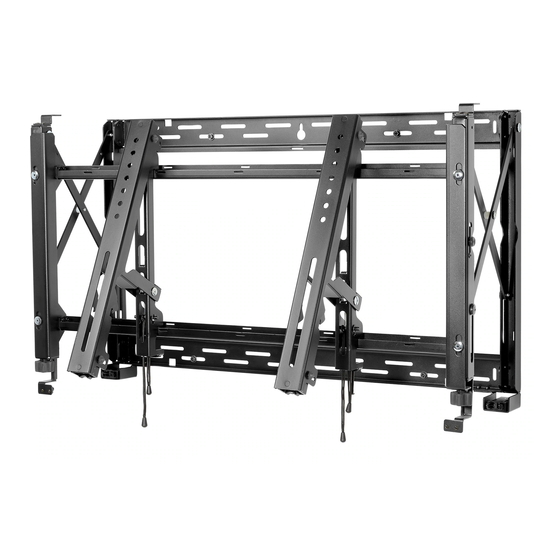
- Page 1 Installation and Assembly: Full Service Video Wall Mount Model: DS-VW765-LQR Max UL Load Capacity: 125 lb (57 kg) 1 of 12 ISSUED: 2013-12-9 SHEET #: 145-9029-2 2014-03-04...
-
Page 2: Table Of Contents
NOTE: Read entire instruction sheet before you start installation and assembly. WARNING • Do not begin to install your Peerless product until you have read and understood the instructions and warnings contained in this Installation Sheet. If you have any questions regarding any of the instructions or warnings, for US customers please call Peerless customer care at 1-800-865-2112, for all international customers, please contact your local distributor. -
Page 3: Vertical And Horizontal Video Wall Mount Spacing And Assembly Formulas
Vertical Video Wall Spacing Location If DS-VWS0## Wall Plate Spacer Kit is not available use diagram below to determine vertical spacing. To determine lower mounting slot position of second mount, add display height to (Y1) or (Y2) DISPLAY HEIGHT 10" .75"... -
Page 4: Parts List
Parts List Part Description Quantity Part Number pull-out mount assembly 145-T1860 adapter bracket 145-T1926 mesh sleeve 600-1014 M5 x 10mm socket pin type-F screw (not used) 520-1164 #14 x 2.5” hex head wood screw 5S1-015-C03 concrete anchor 590-0320 fender washer 540-1008 nylon shoulder washer 590-2233... -
Page 5: Installation To Wood Stud Wall
Installation to Wood Stud Wall WARNING • Installer must verify that the supporting surface will safely support the combined load of the equipment and all attached hardware and components. • Tighten wood screws so that wall plate is firmly attached, but do not overtighten. Overtightening can damage the screws, greatly reducing their holding power. -
Page 6: Installation To Solid Concrete Or Cinder Block Wall
Installation to Solid Concrete or Cinder Block Wall WARNING • When installing Peerless wall mounts on a concrete wall, the wall must be at least 8 thick with a minimum compres- " sive strength of 2000 psi. • When installing Peerless wall mounts on a cinder block wall, the cinder blocks must meet ASTM C-90 specifications and have a minimum nominal width of 8 . -
Page 7: Attaching Adapter Brackets To Display
Attaching Adapter Brackets to Display NOTE: Make sure to use largest hole pattern on back of display. Attach adapter brackets (B) to back of display using four M6 x 12 mm socket pin screws (I) with nylon shoulder washer (H), or four M8 x 15 mm socket pin screws (J) as shown below. - Page 8 Display Adjustment Use legend below to determine position of display. NOTE: Each knob can be adjusted independently for fine tuning adjustments. Turn knob CLOCKWISE to raise side Turn knob COUNTER-CLOCKWISE to lower side DOWN ROTATE LEFT ROTATE RIGHT 8 of 12 ISSUED: 2013-12-9 SHEET #: 145-9029-2 2014-03-04...
-
Page 9: Display Adjustment
Display Adjustment Use legend below to determine position of display. NOTE: Each knob can be adjusted independently for fine tuning adjustments. Turn knob CLOCKWISE to move corner toward the wall Turn knob COUNTER-CLOCKWISE to move corner away from the wall TILT FORWARD BACK BACK BACK SIDE SIDE SIDE TILT RIGHT TILT LEFT TILT BACKWARD BACK... -
Page 10: Cable Management
Cable Management Display cables can be routed through top or bottom of pull-out mount assembly (A). NOTE: Use mesh sleeve (M) and cable ties (L) for cable management. NOTE: Cable ties and cable management slots on pull-out mount assembly (A) can be used to secure display cables. -
Page 11: Open Or Close Adapter Brackets
Open Adapter Brackets: Long Cords Open adapter brackets (B) by pulling down on the long cords while pulling bottom of display away from wall. NOTE: Kick stand will automatically engage. Make sure kick stand is set in position before resting the display. NOTE: Extended position is for service access only. -
Page 12: Multiple Displays (Optional): Installing Spacer Kit (Sold Separately)
Optional for Multiple Displays: Installing Spacer Kit (Sold Separately) Call customer care to assist with choosing the proper spacers for displays used. Slide spacers into tab of mounted wall plate as shown. Keeping spacers flush against wall plate, fasten two #10 x 3/4" wood screws as shown. There must be two spacers placed on the same side as the additional wall plate. Align the tabs of the additional wall plate flush with the spacers. Follow main instruction for proper installation of additional wall plates.
Need help?
Do you have a question about the DS-VW765-LQR and is the answer not in the manual?
Questions and answers