peerless-AV Mobile Videowall Trolley PDVWM 3x3 46 55 L Installation And Assembly Manual
3 x 3 cart
Hide thumbs
Also See for Mobile Videowall Trolley PDVWM 3x3 46 55 L:
- Accessory installation manual (2 pages)

Related Manuals for peerless-AV Mobile Videowall Trolley PDVWM 3x3 46 55 L


Summary of Contents for peerless-AV Mobile Videowall Trolley PDVWM 3x3 46 55 L
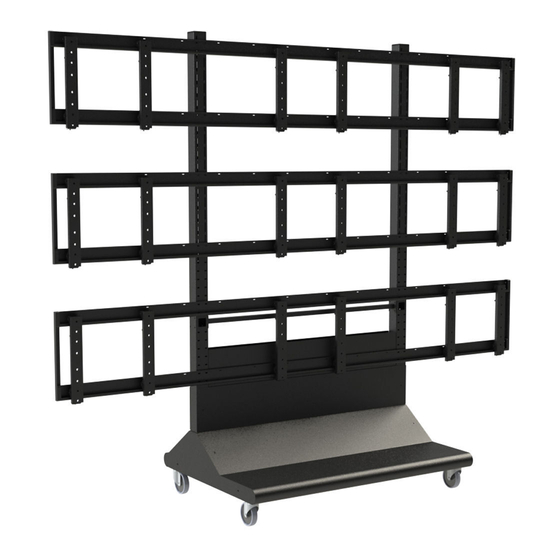
- Page 1 Installation and Assembly: 3 x 3 Cart Model: DS-VWC655-3x3 Maximum Load Capacity 1000 Ibs (454 kg) 1 of 13 ISSUED: 11-16-11 SHEET #: 125-9265-2 02-24-12 Visit the Peerless Web Site at www.peerlessmounts.com For customer care call 1-800-865-2112.
-
Page 2: Parts List
PARTS LIST Description Qty. Part # vertical support 145-1543 adapter brackets 145-1711 horizontal support 145-1382 shelf 145-1361 5" caster 600-0026 1/4" flat washer 540-9440 M8 x 25 mm phillips screw 520-1031 5/16 flat washer 540-9406 5/16 split washer 540-9405 1/4-20 x 3.5" hex head screw 520-1656 1/4-20 nylock nut 530-9413... - Page 3 3 of 13 ISSUED: 11-16-11 SHEET #: 125-9265-2 02-24-12 Visit the Peerless Web Site at www.peerlessmounts.com For customer care call 1-800-865-2112.
- Page 4 Assembling Cart Attach two horizontal supports (C) to vertical support (A) using eight 1/4-20 x 3.5" hex head screws (J), 1/4" SAE washers (F) and 1/4-20 nylock nuts (K). Attach horizontal support (C) to vertical supports (A) Attach horizontal supports (C) to second using eight 1/4-20 x 3.5"...
- Page 5 Attach four swivel casters (E) to vertical supports (A) using sixteen M8 x 25 mm pan phillips screws (G), split washers (I) and 5/16" SAE flat washers (H). Attach two rail brackets (Y) together using two rail connection brackets (X) with eight M5 x 10 mm pan phillips screws (AA), lock washers (CC), and flat washers (BB).
- Page 6 Determine position of horizontal rails assemblies using the formula below. 1. locate the position of the lower horizontal rail assemblies and attach to vertical supports (A). 2. Use display height to determine location of upper horizontal rail assemblies, NOTE: Horizontal rail assemblies must be secured using twenty-four 1/4-20 x 3.5" hex head screws (J). X = HEIGHT OF DISPLAY HORIZONTAl RAIl ASSEMBly DISTANCE...
-
Page 7: Cable Management
Attach three horizontal rails assemblies onto vertical supports (A) using twenty-four 1/4-20 x 3.5" hex head screws (J), 1/4" SAE washers (F) and 1/4-20 nylock nuts (K) as shown in detail 2. Make sure that horizontal rail assemblies are level then tighten all 1/4-20 x 3.5" hex head screws (J). place two tube caps (R) into tops of vertical supports (A) as shown in detail 2. -
Page 8: Right Side
NOTE: Connection brackets (GG) orientation. place connection brackets (GG) onto rail connection brackets (X) as shown below. RIGHT SIDE FRONT OF DISPLAY CART LEFT SIDE FRONT OF DISPLAY CART 8 of 13 ISSUED: 11-16-11 SHEET #: 125-9265-2 02-24-12 Visit the Peerless Web Site at www.peerlessmounts.com For customer care call 1-800-865-2112. - Page 9 Attach connection brackets (GG) onto rail connection brackets (X) as shown below. Secure one connection brackets (GG) with four M5 x 10 mm phillips screws (AA), lock washers (CC), and flat washers (BB) as shown below. Repeat step for remaining three connection brackets (GG). AA CC RIGHT SIDE SHOWN ABOVE 9 of 13...
- Page 10 Attach adapter brackets (B) to back of display using four M6 x 12 mm phillips screws (O) or M6 x 16 mm phillips screw (HH) with nylon shoulder washer (L), or four M8 x 15 mm phillips screws (N) as shown below. Adapter Bracket Mounting Patterns 200 mm MIN 600 mm MAX...
- Page 11 fasten shelf (D) onto horizontal support (C) using three self-drilling screws (FF) as shown below. 11 of 13 ISSUED: 11-16-11 SHEET #: 125-9265-2 02-24-12 Visit the Peerless Web Site at www.peerlessmounts.com For customer care call 1-800-865-2112.
- Page 12 Adapter Bracket Adjustment Use legend below to determine position of display. NOTE: Each knob can be adjusted independently for fine tuning angle adjustments. Turn knobs CLOCKWISE to raise display height. Turn knobs CLOCKWISE to push out display. Turn knobs COUNTER-CLOCKWISE to lower display height. Turn knob COUNTER-CLOCKWISE to pull in display.
-
Page 13: Back View
Attaching Covers NOTE: Position bottom front and back covers first position front bottom cover (U). Secure covers in place using four decorative screws (DD) as shown below. position back bottom cover (V). Secure covers in place using four decorative screws (DD) as shown below. position upper cover (W) on front of vertical supports (A).
Need help?
Do you have a question about the Mobile Videowall Trolley PDVWM 3x3 46 55 L and is the answer not in the manual?
Questions and answers