Advertisement
Quick Links
1. All dimensions:
Font = Arial Regular 8 pt
mm color = black
inch color = Pantone 201C (SMYK)
2. Captions:
Font = Century Gothic/Bold 10 pt
Color = black
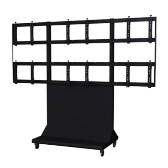
Installation and Assembly: 3 x 2 Cart
PRODUCT DATA SHEET TEMPLATE
Model: DS-VWC555-3x2
99.52"
(2528mm)
The Video Wall Cart shall be a Peerless model DS-VWC555-3X2 and shall be located where indicated on the plans. Assembly
Visit the Peerless Web Site at www.peerless-av.com
119.21"
(3028mm)
114.66"
(2912mm)
FRONT VIEW
A R C H I T E C T S S P E C I F I C A T I O N S
and installation shall be done according to instructions provided by the manufacturer.
3. Sub-captions:
Font = Century Gothic/Bold 8 pt
Color = black
4. Line drawings:
Color = black
Line weight = from .5 to 1 pt (visual call depending on drawing)
All arrows must be the same style
COMPATIBILITY FORMULA
Display width must be ≥ 39.75"
Display height must be no < 31.94"
Two display widths + hole pattern width must be <114.65"
31.94"
15.75"
(811mm)
(400mm)
11.81"
(300mm)
12.14"
(308mm)
39.28"
(998mm)
SIDE VIEW
1
PLP
ADAPTER
PLATE
7.87"
5.91"
(200mm)
(150mm)
ADAPTER BRACKET
Maximum Load Capacity 650lbs (295kg)
ISSUED: 04/24/2013 SHEET #: 125-9433
For customer care call 1-800-865-2112.
W: 7.8883" x H: 4.3737"
0.63"
(16mm)
0.63"
(16mm)
13.78"
(350mm)
SIDE VIEW
± 0.63" (16mm)
Height and Depth
Adjustment
Advertisement

Related Manuals for peerless-AV DS-VWC555-3x2


Summary of Contents for peerless-AV DS-VWC555-3x2
- Page 1 A R C H I T E C T S S P E C I F I C A T I O N S The Video Wall Cart shall be a Peerless model DS-VWC555-3X2 and shall be located where indicated on the plans. Assembly and installation shall be done according to instructions provided by the manufacturer.
- Page 2 520-1320 GG connection bracket 145-1504 HH M6 x 16mm phillips screw 520-9274 Before beginning, make sure you have all parts shown ISSUED: 04/24/2013 SHEET #: 125-9433 Visit the Peerless Web Site at www.peerless-av.com For customer care call 1-800-865-2112.
- Page 3 ISSUED: 04/24/2013 SHEET #: 125-9433 Visit the Peerless Web Site at www.peerless-av.com For customer care call 1-800-865-2112.
- Page 4 ISSUED: 04/24/2013 SHEET #: 125-9433 Visit the Peerless Web Site at www.peerless-av.com For customer care call 1-800-865-2112.
- Page 5 (A) using eight 1/4-20 x 3.5" hex head screws (J), 1/4" SAE washers (F) and 1/4-20 1/4" SAE washers (F) and 1/4-20 nylock nuts (K). nylock nuts (K). ISSUED: 04/24/2013 SHEET #: 125-9433 Visit the Peerless Web Site at www.peerless-av.com For customer care call 1-800-865-2112.
- Page 6 Attach two rail brackets (Y) together using two rail connection brackets (X) with eight M5 x 10 mm pan phillips screws (AA), lock washers (CC), and flat washers (BB). BB CC ISSUED: 04/24/2013 SHEET #: 125-9433 Visit the Peerless Web Site at www.peerless-av.com For customer care call 1-800-865-2112.
- Page 7 NOTE: Horizontal rail assemblies must be secured using sixteen 1/4-20 x 3.5" hex head screws (J). X = HEIGHT OF DISPLAY HORIZONTAL RAIL ASSEMBLY DISTANCE UPPER HORIZONTAL RAIL EQUALS DISPLAY HEIGHT DISPLAY HEIGHT LOWER HORIZONTAL RAIL ISSUED: 04/24/2013 SHEET #: 125-9433 Visit the Peerless Web Site at www.peerless-av.com For customer care call 1-800-865-2112.
-
Page 8: Cable Management
18" mesh sleeve (M) before securing. Display cables can be secured to horizontal rails assemblies using cable ties (Q) as needed through slots in horizontal rails (Y). SLOT ISSUED: 04/24/2013 SHEET #: 125-9433 Visit the Peerless Web Site at www.peerless-av.com For customer care call 1-800-865-2112. -
Page 9: Right Side
Place connection brackets (GG) onto rail connection brackets (X) as shown below. RIGHT SIDE FRONT OF DISPLAY CART LEFT SIDE FRONT OF DISPLAY CART ISSUED: 04/24/2013 SHEET #: 125-9433 Visit the Peerless Web Site at www.peerless-av.com For customer care call 1-800-865-2112. - Page 10 Secure one connection brackets (GG) with four M5 x 10 mm phillips screws (AA), lock washers (CC), and flat washers (BB) as shown below. Repeat step for remaining connection bracket (GG). AA CC FRONT BACK ISSUED: 04/24/2013 SHEET #: 125-9433 Visit the Peerless Web Site at www.peerless-av.com For customer care call 1-800-865-2112.
- Page 11 NOTE: Once display is located in desired position, tighten security screws as shown in detail 4. DISPLAY NOT SHOWN FOR CLARITY TIGHTEN SECURITY SCREW DETAIL 4 ISSUED: 04/24/2013 SHEET #: 125-9433 Visit the Peerless Web Site at www.peerless-av.com For customer care call 1-800-865-2112.
- Page 12 Fasten shelf (D) onto horizontal support (C) using three self-drilling screws (FF) as shown below. ISSUED: 04/24/2013 SHEET #: 125-9433 Visit the Peerless Web Site at www.peerless-av.com For customer care call 1-800-865-2112.
-
Page 13: Adapter Bracket Adjustment
Turn knobs CLOCKWISE to push out display. Turn knobs COUNTER-CLOCKWISE to lower display height. Turn knob COUNTER-CLOCKWISE to pull in display. DOWN KNOB ISSUED: 04/24/2013 SHEET #: 125-9433 Visit the Peerless Web Site at www.peerless-av.com For customer care call 1-800-865-2112. -
Page 14: Back View
1/4-20 x 3.5” hex head screws (J), two 1/4” flat washer (F), and two 1/4-20 nylock nuts (K). Secure base of covers in place using two decorative screws (DD) as shown below. BACK VIEW ISSUED: 04/24/2013 SHEET #: 125-9433 Visit the Peerless Web Site at www.peerless-av.com For customer care call 1-800-865-2112. - Page 15 (Z) as shown to right. Attach side cover to vertical support (A) so that it goes inside the lower front and back covers (U and V). ISSUED: 04/24/2013 SHEET #: 125-9433 Visit the Peerless Web Site at www.peerless-av.com For customer care call 1-800-865-2112.
- Page 16 Peerless-AV 2300 White Oak Circle Aurora, IL 60502 Email: tech@peerlessmounts.com Ph: (800) 865-2112 Fax: (800) 359-6500 www.peerless-av.com © 2013, Peerless Industries, Inc. ISSUED: 04/24/2013 SHEET #: 125-9433 Visit the Peerless Web Site at www.peerless-av.com For customer care call 1-800-865-2112.
Need help?
Do you have a question about the DS-VWC555-3x2 and is the answer not in the manual?
Questions and answers