
Related Manuals for peerless-AV SmartMount DS-C560-1X3


Summary of Contents for peerless-AV SmartMount DS-C560-1X3
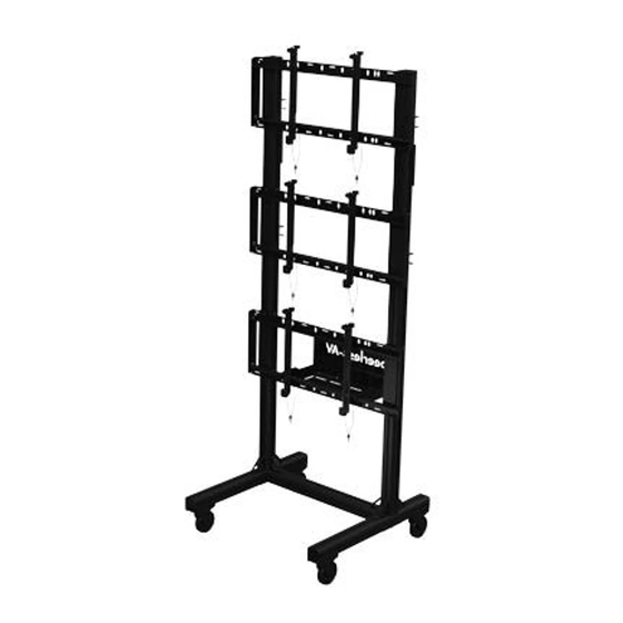
- Page 1 DS-C560-1X3 46" - 60" 500 lb (117 - 152 cm) (227 kg) 2015-06-30 #:009-9119-3 (2016-05-16)
- Page 2 This page intentionally left blank. 2015-06-30 #:009-9119-3 (2016-05-16)
- Page 3 WARNING Do not begin to install product until you have read and understood the instructions and warnings contained in this user guide. Always use an assistant or mechanical lifting equipment to safely lift and position equipment. This product must be installed onto fl at, hard, level surface to prevent tipping. The cart or stand is not affi xed or secured to the fl...
-
Page 4: Table Of Contents
Parts (Before beginning, make sure you have all parts shown below). Parts List Description Part # caster, 5" swivel 600-0026 caster support 145-T1799 cover 145-T1809 base support tube 145-T1812 base support 560-T1261 left adaptor bracket 146-1609 right adaptor bracket 146-1608 base leg 145-T1767 horizontal leg support... - Page 5 M ( 3 ) N ( 1 ) O ( 1 ) P ( 2 ) computer cover cross support computer shelf extension adaptor Q ( 4 ) R ( 4 ) S ( 120 ) T ( 40 ) U ( 24 ) cord knurled...
-
Page 6: A ( 4 )
(5mm) S (4) Do not fully tighten hardware T (2) S (2) SIDE VIEW 2015-06-30 #:009-9119-3 (2016-05-16) - Page 7 T (2) (5mm) T (2) S (4) T (2) T (2) S (4) 2015-06-30 #:009-9119-3 (2016-05-16)
-
Page 8: C ( 6 )
FLUSH TIGHTEN EDGES CONNECTING HARDWARE Casters must be fl ush to end of horizontal leg support. S (4) SIDE VIEW W (2) Do not fully tighten hardware 2015-06-30 #:009-9119-3 (2016-05-16) - Page 9 TIGHTEN CONNECTING HARDWARE Do not fully tighten hardware S (4) W (2) 2015-06-30 #:009-9119-3 (2016-05-16)
-
Page 10: K ( 2 )
K (2) P (2) TIGHTEN CONNECTING HARDWARE TIGHTEN LOCK WHEELS CONNECTING HARDWARE 2015-06-30 #:009-9119-3 (2016-05-16) - Page 11 S (4) 1/8" 1/8" (3mm) (3mm) T (4) S (2) L (3) TIGHTEN L (3) CONNECTING HARDWARE 2015-06-30 #:009-9119-3 (2016-05-16)
- Page 12 U (4) 2015-06-30 #:009-9119-3 (2016-05-16)
- Page 13 TIGHTEN CONNECTING HARDWARE M (3) TIGHTEN TIGHTEN HARDWARE HARDWARE (X2) (X2) Cross supports must center on vertical leg supports. 2015-06-30 #:009-9119-3 (2016-05-16)
- Page 14 11-1 Center adapter brackets vertically on back of screen. 11-2 OPTIONAL: Use (S) to lock mechanism on adaptor bracket 2015-06-30 #:009-9119-3 (2016-05-16)
- Page 15 12-1 Must hang displays on bottom row fi rst; Secure pin in "locked" position. 12-2 OPTIONAL: Insert M5 x 10mm type-F socket pin screws (V) to lock latches. "LOCKED" POSITION 2015-06-30 #:009-9119-3 (2016-05-16)
- Page 16 Display Adjustment TILT FORWARD SIDE SIDE SIDE TILT BACKWARD TILT RIGHT TILT LEFT SIDE DOWN ROTATE LEFT ROTATE RIGHT 2015-06-30 #:009-9119-3 (2016-05-16)
- Page 17 TIGHTEN CONNECTING HARDWARE OPTIONAL: Unlock wheels to move cart to desired location; Lock wheels before hanging screens. TOP VIEW LOCK WHEELS 2015-06-30 #:009-9119-3 (2016-05-16)
- Page 18 14-1 14-2 1/8" (3mm) V (2) TIGHTEN CONNECTING HARDWARE 2015-06-30 #:009-9119-3 (2016-05-16)
- Page 19 Route cables through cord brackets. 2015-06-30 #:009-9119-3 (2016-05-16)
- Page 20 Display Removal Pull down on bracket cords and hold. Swing screen away from cart and lift to remove. Remove displays from top row fi rst. "UNLOCKED" POSITION 2015-06-30 #:009-9119-3 (2016-05-16)
- Page 21 Repeat step 16 to remove displays from middle row second. "UNLOCKED" POSITION Repeat step 16 to remove displays from bottom row last. "UNLOCKED" POSITION 2015-06-30 #:009-9119-3 (2016-05-16)
- Page 22 This page intentionally left blank. 2015-06-30 #:009-9119-3 (2016-05-16)
- Page 23 LIMITED FIVE-YEAR WARRANTY Peerless Industries, Inc. (“Peerless”) warrants to original end-users of Peerless ® products will be free from defects in material and workmanship, under normal use, for a period of fi ve years from the date of purchase by the original end-user (but in no case longer than six years after the date of the product's manufacture).
- Page 24 Peerless-AV Peerless-AV Europe Peerless-AV de Mexico 2300 White Oak Circle Unit 3 Watford Interchange, Ave de las Industrias 413 Aurora, IL 60502 Colonial Way, Watford, Herts, Parque Industrial Escobedo Email: tech@peerlessmounts.com WD24 4WP, United Kingdom Escobedo N.L Mexico 66050 Ph: (800) 865-2112...
Need help?
Do you have a question about the SmartMount DS-C560-1X3 and is the answer not in the manual?
Questions and answers