Table of Contents
Advertisement
Quick Links
Advertisement
Table of Contents

Subscribe to Our Youtube Channel
Related Manuals for peerless-AV DS-VW795-QR


Summary of Contents for peerless-AV DS-VW795-QR
- Page 1 Installation and Assembly: Full Service Video Wall Mount Model: DS-VW795-QR Max UL Load Capacity: 225 lb (102 kg) 2300 White Oak Circle • Aurora, Il 60502 • (800) 865-2112 • Fax: (800) 359-6500 • www.peerless-av.com ISSUED: 2014-03-18 SHEET #: 125-9585-1...
-
Page 2: Table Of Contents
NOTE: Read entire instruction sheet before you start installation and assembly. WARNING • Do not begin to install your Peerless product until you have read and understood the instructions and warnings contained in this Installation Sheet. If you have any questions regarding any of the instructions or warnings, for US customers please call Peerless customer care at 1-800-865-2112, for all international customers, please contact your local distributor. -
Page 3: Vertical And Horizontal Video Wall Mount Spacing And Assembly Formulas
Vertical Video Wall Spacing Location If DS-VWS0## Wall Plate Spacer Kit is not available use diagram below to determine vertical spacing. To determine lower mounting slot position of second mount, use vertical spacing formula. Note: This formula is based on the VESA pattern being centered on the back of the display. DISPLAY HEIGHT 12.375... -
Page 4: Parts List
Parts List Part Description Quantity Part Number wall side assembly 145-T1940 adapter bracket 145-T1938 hex wood screw 5S1-015-C03 8mm anchor 590-0320 nylon shoulder washer 590-2233 M5 x 10mm socket pin type-F screw 520-1164 M8 x 15mm socket pin screw 520-1068 M6 x 12mm socket pin screw 520-1050 fender washer... -
Page 5: Installation To Wood Stud Wall
Installation to Wood Stud Wall WARNING • Installer must verify that the supporting surface will safely support the combined load of the equipment and all attached hardware and components. • Tighten wood screws so that wall plate is fi rmly attached, but do not overtighten. -
Page 6: Installation To Solid Concrete Or Cinder Block Wall
Installation to Solid Concrete or Cinder Block Wall WARNING • When installing Peerless wall mounts on a concrete wall, the wall must be at least 8 thick with a minimum compres- " sive strength of 2000 psi. • When installing Peerless wall mounts on a cinder block wall, the cinder blocks must meet ASTM C-90 specifi cations and have a minimum nominal width of 8 . -
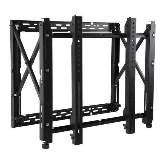
Page 7: Attaching Adapter Brackets To Display
Attaching Adapter Brackets to Display NOTE: Make sure to use largest hole pattern on back of display. Attach adapter brackets (B) to back of display using four M6 x 12 mm socket pin screws (H) with nylon shoulder washer (E), or four M8 x 15 mm socket pin screws (G) as shown below. - Page 8 Display Adjustment Use legend below to determine position of display. NOTE: Each knob can be adjusted independently for fi ne tuning adjustments. Turn knob CLOCKWISE to raise side Turn knob COUNTER-CLOCKWISE to lower side DOWN ROTATE LEFT ROTATE RIGHT 8 of 11 ISSUED: 2014-03-18 SHEET #: 125-9585-1...
-
Page 9: Display Adjustment
Display Adjustment Use legend below to determine position of display. NOTE: Each knob can be adjusted independently for fi ne tuning adjustments. Turn knob CLOCKWISE to move corner toward the wall Turn knob COUNTER-CLOCKWISE to move corner away from the wall TILT FORWARD BACK BACK... -
Page 10: Cable Management
Cable Management Display cables can be routed through top or bottom of pull-out mount assembly (A). NOTE: Use mesh sleeve (K) and cable ties (L) for cable management. NOTE: Cable ties and cable management slots on pull-out mount assembly (A) can be used to secure display cables. - Page 11 Peerless in connection with the sale of any Peerless product. This warranty gives specifi c legal rights, and you may also have other rights which vary from state to state. Patent Pending Peerless-AV 2300 White Oak Circle Aurora, IL 60502 Email: tech@peerlessmounts.com...
Need help?
Do you have a question about the DS-VW795-QR and is the answer not in the manual?
Questions and answers