Table of Contents
Advertisement
Available languages
Available languages
Quick Links
Advertisement
Chapters
Table of Contents

Related Manuals for Cadel family


Summary of Contents for Cadel family
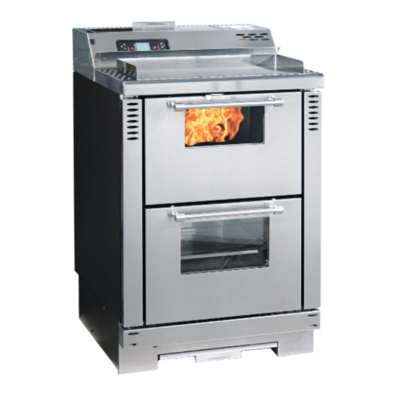
- Page 1 PELLET COOKING STOVE installation use and maintenance manual PELLETKEUKEN handleiding voor installatie gebruik en onderhoud family ©2015 CADEL srl | All rights reserved – tutti i diritti riservati...
-
Page 2: Table Of Contents
12.11 CLOCK SETTING ........... 20 12.12 DAILY PROGRAMMING ......20 12.13 WEEKEND PROGRAMMING ......20 12.14 WEEKLY PROGRAMMING ......20 12.15 PELLET SUPPLY ..........21 12.16 REMOTE CONTROL ........21 13 COOKING METHODS ......... 22 13.1 PLATE COOKING ........... 22 FAMILY... -
Page 3: Manual Simbology
• All the pictures carried in this manual are only for indicative and explanatory purpose and could therefore slightly differ from your appliance. • The referring appliance is those you purchased. • In case of doubts or difficulties in the comprehension or for problems not described in this manual, please promptly contact your distributor or installer. FAMILY... -
Page 4: Safety Requirements
• If the auger is blocked by a foreign object (for example: nails), and if it needs to be cleaned, do not remove the hand rejector and do not touch the auger. Please contact the Technical Assistance service. FAMILY... -
Page 5: Warranty Conditions
The user will also be charged for any costs incurred to remedy the incorrect technical interventions, tampering FAMILY... -
Page 6: Spare Parts
European Standards (EN 15287 - EN 13384 - EN 1856 - EN 1443) and UNI 10683:2012. It provides instructions for a good and correct execution of the chimney flue but it does not absolutely replace the current standards which the qualified manufacturer/installer should comply with. FAMILY... -
Page 7: Chimney Flue
Fig. 2 page 7 Height over the ridge of the roof = 0,5 mt Roof inclination ≥ 10° 90° Measured distance at 90° from the roof surface = 1,3 mt • The chimney flue must be sealed from fumes. FAMILY... -
Page 8: Height-Depression
• The hole width for fumes exhaust must be the double of the chimney flue width and fitted in a way that the fume exhaust is assured also in case of wind. • It should prevent the infiltration of rain, snow and animals. FAMILY... -
Page 9: Chimney Components
Fume outlet Chimney flue Termal insulation External wall Chimney union Fume pipe Heat generator Inspection door T-union with inspection plug EXTERNAL AIR INLET Fig. 6 - Direct air inflow LEGEND Fig. 6 page 9 Room to ventilate External air inlet FAMILY... -
Page 10: Combustion Air Drawn Directly From Outside
(consult an Authorized Technician) or review the length and the type of connection made. Check with local authorities if there are restrictive regulations regarding combustion air intake: if present, they must be applied. FAMILY... -
Page 11: Chimney Flue Connection
(see Fig. 8 page 11). Fig. 8 - Prohibition • It is forbidden to connect any other appliance (wood stoves, cooker hoods, boilers, etc...). • The fume conduit must be placed at a distance of minimum 500 mm from flammable or heat-susceptible components. FAMILY... -
Page 12: Examples Of Correct Installation
Chimney inspection entrance Minimum safety distance = 0,5 mt Inclination ≥ 3° Level section ≤ 1 mt • Old chimney flue with an inserted pipe of minimum Ø100/120 mm and with an external door which enables the chimney cleaning. FAMILY... -
Page 13: Fuel
(pellets), causing a flame raising or drapping with a possible switching off at lower powers. • Depending on the type of pellets it could be necessary a parameters adjustment, please contact an Authorized Assistance Service. FAMILY... -
Page 14: Installation
OVERALL DIMENSIONS Fig. 12 - General dimensions LEGEND Fig. 12 page 14 60 cm 96 cm 60 cm 73,5 cm 7 cm 50,5 cm 21,5 cm 14 cm 7 cm Hole combustion air inlet d.6 cm Exhaust fumes d.8 cm FAMILY... -
Page 15: General Installation
Fig. 14 - Embed cooking stove 11.4 ELECTRIC CONNECTION Warning: the appliance must be installed by an authorized technician! • The electric connection occurs through a cable with plug put in an electric socket which is able to support FAMILY... -
Page 16: Connection To The External Thermostat
• The stove is endowed with a ventilation system. Fig. 16 - Filter position LEGEND Fig. 16 page 16 Anti-dust filter • The air moved by the motorized fans keeps the stove at a lower temperature, avoiding excessive strain on the materials comprising it. FAMILY... -
Page 17: Use
P3: it enables to enter set temperature and User and Technician parameters menu. P4: switching on and off, alarm reset and exit from programming. P5 and P6: increase and decrease the calorific power from 1 to 5. Chrono: active time programming. Ignition plug: active ignition. Auger: active. FAMILY... -
Page 18: User Menu
P3 key, then P1 key for starting up and P4 key for stop. It shows all parameters connected to the stove state: this is a menu for the Authorized STOVE STATE Techinician TECHNICA SETTING Only for the Authorized Technician. FAMILY... -
Page 19: Start Up
12.8 TEMPERATURE SETTING • To modify the ambient temperature it is sufficient to press P1 and P2 keys according to the desired temperature inside the menu "SET TEMP ROOM". • To see the set temperature, press once P1 key. FAMILY... -
Page 20: Fume Temperature
• Press P5: the display shows "SATURDAY PROG-1", with P1 and P2 keys set "ON" or "OFF"". • Press P5: the display shows "SUNDAY PROG-1", with P1 and P2 keys set "ON" or "OFF". • Now press P5 and repeat all the previous instructions for Prog-2, Prog-3, Prog-4. • To exit press three times P4. FAMILY... -
Page 21: Pellet Supply
Button 1 Increase the desired temperature Button 2 Decrease the desired temperature Button 3 On / off Button 4 Menu Button 5 Decrease the power level from 5 to 1 Button 6 Increase the power level from 1 to 5 FAMILY... -
Page 22: Cooking Methods
• Reset the error with P4 key. The stove carries out the phase "FINAL CLEANING" and the is in "OFF". • Check the type of glitch as ALARMS page 27. • Clean the burning pot and start the stove up again with P4 key. FAMILY... -
Page 23: Fan Failure" Alarm
• If the stove had been using continuously and intensely, the whole system (chimney included), must be cleaned and checked more frequently. • In case of replacement of damaged pieces please ask for the original spare part at the Autorized Retailer. FAMILY... -
Page 24: Combustion Chamber Cleaning
Per each pellets supply, check the probable presence of meal, sawdust and other remanins on the hopper bottom. If present, they must be removed with the aid of a vacuum cleaner (see Fig. 27 page 24). Fig. 27 - Hopper and auger cleaning FAMILY... -
Page 25: Fume Chamber Cleaning
FUME FAN CLEANING Clean every the year the fume fan from ash or dust which can cause a blade unbalance and a greater noise. As this operation is so delicate it must therefore be executed by an Authorized Technician. FAMILY... -
Page 26: Room Fan Cleaning
GASKET REPLACEMENT In case of deterioration of fire door, hopper or fume chamber gaskets, it is necessary to replace them by an autorized technician in order to guarantee the good running of the stove. Use exclusively original spare parts. FAMILY... -
Page 27: Glass Cleaning
Faulty fume probe Replace the fume probe. Faulty mother board Replace the electronic board. AL 3 - HOT EXHAUST The exchanger fan does Replace the ambient fan. not work Too high pellet drop Adjust the pellet loading. value FAMILY... - Page 28 Temporary power cut manula reset thermostat. Let the stove cooling, reset and SAFETY start the stove up again. Faulty manual reset Replace the manual reset thermostat. thermostat Faulty mother board Replace the mother board. FAMILY...
-
Page 29: Problem Solving
Before of every Authorized Technician intervention, the same Technician has the duty to check if the parameters of the mother board correspond to those of the table you own. In case of doubts regarding the use of the stove, please contact ALWAYS the Authorized Technician on order to avoi irreparable damages! FAMILY... - Page 30 "phase 1" Check if on the display there is an Have the stove checked. "ACTIVE ALARM" Stove running and Automatica The stove is at minimum, fume fan at maximum. NO display showing burning pot PROBLEM! "BURN POT CLEAN" cleaning FAMILY...
-
Page 31: Technical Datas
Now we give some instructions for the Authorized Technician to take into consideration to have access to stove mechanical components. For fuse replacement in the electric socket which lies on the under of the stove, extract the fuses to change with the aid of a screwdriver in the shutter (see ). FAMILY... - Page 32 • Pull the stove out of its built-in position. • Loosen the 8 screws on the left and right hand side covers of the base (see Fig. 36 page 32). • Detach the control panel and plinth (see above). FAMILY...
- Page 33 • Loosen the 4 screws on the spark plug cover (see Fig. 37 page 33). • Loosen the M4 grub screw holding the spark plug under the round head of the spark plug support. Fig. 38 - Rear view LEGEND Fig. 38 page 33 Tank lid Display tank lid Auger FAMILY...
-
Page 34: Features
• Loosen the 3 screws on the inspection panel + the 6 screws on the extractor cover (see Fig. 38 page 33) . • If you need to replace the auger, loosen the 2 screws on the hand protection plate. 17.2 FEATURES DESCRIPTION FAMILY 7,5 kW WIDTH 60 cm DEPTH 60 cm... - Page 35 12.10 UITSCHAKELING ........... 53 12.11 INSTELLINGEN KLOK ........53 12.12 DAGPROGRAMMERING ......53 12.13 WEEKENDPROGRAMMERING ..... 53 12.14 WEEKPROGRAMMERING ......54 12.15 PELLETS BIJVULLEN ........54 12.16 AFSTANDSBEDIENING ........54 13 BEREIDINGSWIJZEN ..........55 13.1 BEREIDING OP DE PLAAT ......55 FAMILY...
-
Page 36: In De Handleiding Gebruikte Symbolen
• Het apparaat waarnaar verwezen wordt, is het apparaat dat u gekocht heeft. • In geval van twijfel, als u iets niet begrijpt, of wanneer zich problemen voordoen die niet door deze handleiding behandeld worden, verzoeken wij u zo snel mogelijk contact op te nemen met uw distributeur of installateur. FAMILY... -
Page 37: Veiligheidsvoorschriften
Kinderen mogen niet met het toestel spelen. De reiniging en het onderhoud dat door de gebruiker moet worden uitgevoerd, mag niet door kinderen zonder toezicht worden uitgevoerd. FAMILY... -
Page 38: Garantievoorwaarden
• Eventuele corrosie, aanslag of breuken veroorzaakt door zwerfstroom, condens, agressiviteit of zuurheid van het water, onjuist uitgevoerde aanslagwerende behandelingen, watertekort, bezinksel van modder of kalkaanslag. • Inefficiëntie van de schoorstenen, rookgaskanalen of delen van de installatie waarvan het toestel afhangt. FAMILY... -
Page 39: Reserveonderdelen
• leg de kachel niet op één zijde en/of kantel hem niet maar houd hem verticaal of hoe dan ook overeenkomstig de aanwijzingen van de fabrikant; • als de kachel onderdelen van majolica, steen, glas, of hoe dan ook van bijzonder delicate materialen bevat, verplaats het geheel dan zeer voorzichtig. FAMILY... -
Page 40: Rookkanaal
• Het is van essentieel belang dat het rookkanaal volgens de regels van het vak geconstrueerd is en altijd perfect efficiënt gehouden wordt. • Het rookkanaal moet enkelvoudig zijn (zie Fig. 1 op pag. 40 met geïsoleerde inox-buizen (1) of op een bestaand rookkanaal (2). • Beide oplossingen moeten een inspectiedop (3) en/of een inspectieluikje (4) bezitten. FAMILY... -
Page 41: Technische Kenmerken
Fig. 3 - Voorbeeld van een plaatje HOOGTE-ONDERDRUK De onderdruk (trek) van een rookkanaal is ook afhankelijk van diens hoogte. Controleer de onderdruk met de waarden die vermeld worden bij KENMERKEN op KENMERKEN op pag. 68. Minimum hoogte 3,5 meter. FAMILY... -
Page 42: Onderhoud
(zie Fig. 2 op pag. 41). ONDERDELEN VAN DE SCHOORSTEEN Fig. 5 - Onderdelen van de schoorsteen LEGENDA Fig. 5 op pag. 42 Schoorsteenpot Uitstroomweg Rookkanaal Thermische isolatie Buitenmuur Aansluiting van de schoorsteen Rookleiding Warmtegenerator Inspectieluikje T-aansluiting met inspectiedop FAMILY... -
Page 43: Buitenluchtinlaat
• De luchtinlaat moet tot stand gebracht worden op een hoogte vlakbij de vloer, met een extern rooster dat bescherming tegen vogels biedt, en op een wijze dat het door geen enkel object belemmerd wordt. DE VERBRANDINGSLUCHT WORDT RECHTSTREEKS VAN BUITEN GENOMEN Fig. 7 - Luchtinlaat voor installatie FAMILY... -
Page 44: Aansluiting Op Het Rookkanaal
• Het is verboden om de rookafvoer van zich erboven bevindende afzuigkappen in hetzelfde rookkanaal te voeren. • Het is verboden de verbrandingsproducten rechtstreeks via de muur naar buiten af te voeren, of naar gesloten ruimtes, ook wanneer deze onoverdekt zijn (se Fig. 8 op pag. 45). FAMILY... -
Page 45: Voorbeelden Van Correcte Installatie
Fig. 9 - Voorbeeld 1 LEGENDA Fig. 9 op pag. 45 Isolatie Verkleining van Ø100 tot Ø80 mm Inspectiedop Minimum veiligheidsafstand = 0,5 m. • Installatie rookkanaal Ø100/120 mm met boring voor de passage van de grotere buis. Fig. 10 - Voorbeeld 2 FAMILY... -
Page 46: Brandstof
Controleer daarom of de pellets bewaard worden in een droge ruimte, op minstens één meter afstand van de kachel en/of van iedere andere warmtebron. • Er wordt geadviseerd verschillende soorten pellets te proberen die in de markt verkrijgbaar zijn en om de pellets te kiezen die de beste prestaties leveren. FAMILY... -
Page 47: Installatie
• De installatie moet een gemakkelijke toegang tot de elektrische voedingsstekker garanderen (zie ELEKTRISCHE AANSLUITING op pag. 49). • Om meer apparaten te kunnen installeren, moet de buitenluchtinlaat de daarvoor geschikte afmetingen krijgen. 11.2 RUIMTEBESLAG Fig. 12 - Algemene afmetingen LEGENDE Fig. 12 op pag. 47 60 cm FAMILY... -
Page 48: Algemene Installatie
• In enkele landen worden de gemetselde draagmuren ook als ontvlambare muren beschouwd. De keuken kan tussen de meubels worden ingebouwd met de flanken op 10 mm tussenafstand (zie Fig. 14 op pag. 48). Fig. 14 - Inbouwkeuken FAMILY... -
Page 49: Elektrische Aansluiting
• Externe chronothermostaat: stel een "SET TEMP RUIMTE" van 7°C op de kachel in en schakel in menu 03-01 de chronofuncties uit "ACTIVEER CHRONO" ("OFF"). 11.6 VENTILATIE • De kachel is voorzien van ventilatie met stofwerende filter. Fig. 16 - Positie van de filter FAMILY... -
Page 50: Gebruik
P3: om naar set temperatuur en naar het menu van de parameters van gebruiker en technicus te gaan. P4: inschakeling en uitschakeling, deblokkering van eventuele alarmen en verlaten van de programmering. P5 en P6: verhogen en verlagen het warmtevermogen van 1 tot 5. Tijdprogrammering: actief. Rookgassenafzuiger: actief FAMILY... -
Page 51: Gebruikersmenu
Wanneer de kachel voor het eerst ingeschakeld moet worden, is de transportschroef LADEN INITIEEL geheel leeg. Voer zo nodig een voorlading uit door op toets P3 te drukken. Druk vervolgens op P1 om te starten en op P4 om dit te onderbreken. FAMILY... -
Page 52: Starten
Als de vlam na enkele maanden zwak is en/of oranje van kleur, of als het glas de neiging vertoont steeds erg zwart te worden, of de vuurpot de neiging vertoont een aanslag te vormen, reinig dan de kachel, reinig de rookleiding en reinig het rookkanaal. FAMILY... -
Page 53: Geen Energie
• Druk op P5: nu verschijnt de tekst "STOP 2 WEEKEND". Voer met toetsen P1 en P2 de waarde van het tijdstip van inschakeling in, of "OFF". • Druk drie keer op toets P4 om het menu te verlaten. FAMILY... -
Page 54: Weekprogrammering
• Voor de werking heeft men 1 batterij van het type Lithium battery CR 2025 nodig. De gebruikte batterijen bevatten - voor de omgeving - schadelijke metalen en moeten dus in speciale batterijbakken geëlimineerd worden. Fig. 20 - Afstandsbediening FAMILY... -
Page 55: Bereidingswijzen
• Verricht een reset van de fout met toets P4. De kachel voert een fase "EINDE REINIGIN" en "OFF" uit. • Controleer het type fout aan de hand van ALARMEN op pag. 60. • Reinig de vuurpot en herstart de kachel met toets P4. FAMILY... -
Page 56: Alarm "Warm Rookg
• Het is bovendien nodig om de verbrandingskamer minstens één keer per jaar te laten reinigen en de pakkingen na te laten kijken, de motoren en de ventilatoren te laten reinigen en het elektrische gedeelte te laten controleren. FAMILY... -
Page 57: Reiniging Van De Verbrandingskamer
• Pas wanneer de as gedoofd is kan ze weggegooid worden bij het organische afval. • Let op de vlam, als deze rood wordt, zwak is of zwarte rook afgeeft: in dat geval is de vuurpot door afzettingen verstopt en moet gereinigd worden. Indien versleten moet hij vervangen worden. FAMILY... -
Page 58: Reiniging Voorraadbak En Transportschroef
• Reinig met een alleszuiger en zuig de as op die zich binnenin opgehoopt heeft (zie Fig. 30 op pag. 58). • Herhaal de handeling in omgekeerde zin na de reiniging. 15.6 REINIGING ROOKLEIDING Reinig het afvoersysteem iedere maand. Fig. 31 - Reiniging rookleiding FAMILY... -
Page 59: Reiniging Van De Rookgassenafzuiger
Deze werkzaamheden moeten minstens één keer per jaar uitgevoerd worden. 15.11 ALGEMENE REINIGING Voor de reiniging van de externe en interne delen van de kachel dient u geen gebruik te maken van staalsponsjes, zoutzuur of andere corroderende en schurende producten. FAMILY... -
Page 60: Reiniging Van Gelakte Metalen Onderdelen
Reinig de vuurpot en schakel opnieuw in. van inschakeling De temperatuursonde van de rookgassen is Voer een revisie van de kachel uit. afgesloten AL 2 - SONDE ROOKG De temperatuursonde van de rookgassen is Vervang de rookgassensonde. defect FAMILY... - Page 61 De pellets moeten in een droge plaats bewaard worden. Vochtige pellets Controleer dit. De thermische sonde is Vervang de thermische sonde. geblokkeerd De elektronische kaart is Vervang de elektronische kaart. defect AL 6 - GEEN De voorraadbak is leeg Vul de voorraadbak. PELLET FAMILY...
- Page 62 Controleer dit en schakel de kachel opnieuw in. zijn ongunstig De vuurdeur is niet Sluit de vuurdeur correct en controleer of de pakkingen correct gesloten niet verslechterd zijn. Microschakelaar Vervang de microschakelaar van de vuurdeur. vuurdeur kapot of defect FAMILY...
-
Page 63: Oplossing Van De Problemen
Er komen geen object (zoals pellets de spijkers) verbrandingska- mer binnen De reductiemotor van de Vervang de reductiemotor. transportschroef is kapot Controleer of het display niet een Voer een revisie van de kachel uit. actief alarm toont "ALARM ACTIEF" FAMILY... - Page 64 De tempera- tuursonde van Vervang de rookgassensonde. De ventilator- de rookgassen is warmtewisselaar defect blijft draaien, ook al is de kachel De elektronische afgekoeld Vervang de elektronische kaart. kaart is defect FAMILY...
-
Page 65: Technische Gegevens
Gebruik voor de vervanging van de zekeringen in het elektrische stopcontact onder de kachel een schroevendraaier voor schroeven met inkeping. Steek deze in het deurtje en gebruik hem als hefboom (zie ). Trek de te vervangen zekeringen vervolgens naar buiten. Fig. 35 - Deurtje met te verwijderen zekeringen Handel als volgt: FAMILY... - Page 66 • Haal de inbouwkeuken uit zijn zitting. • Draai de 8 schroeven los van de zijafdekkingen rechts en links van de basis (zie Fig. 36 op pag. 66). • Maak het instrumentenbord en de sokkel los, zie vorige punt. Fig. 37 - Vooraanzicht FAMILY...
- Page 67 • Draai de 3 schroeven van het inspectiepaneel + de 6 schroeven van de carter van de afzuiger los (zie Fig. 38 op pag. 67). • Indien het nodig is om de transportschroef te vervangen, moet u ook de 2 schroeven van de bescherming voor de handen losdraaien. FAMILY...
-
Page 68: Kenmerken
17.2 KENMERKEN BESCHRIJVING FAMILY 7,5 kW BREEDTE 60 cm DIEPTE 60 cm HOOGTE 96 cm GEWICHT 130 kg INGEVOERD THERMISCH VERMOGEN (Min/Max) 4,9 - 9,9 kW NOMINAAL THERMISCH VERMOGEN (Min/Max) 3,5 - 7,5 kW EFFICIËNTIE (Min/Max) 71 - 76 % TEMPERATUUR ROOKGASSEN 141 - 203 °C... - Page 69 NOTE...
- Page 70 NOTE...
- Page 71 NOTE...
- Page 72 · · pelletkachels houtkachels houtkeukens · thermokachel open haard pellets CADEL srl FREEPOINT by Cadel Via Foresto Sud, 7 31025 Santa Lucia di Piave (TV) - ITALY tel. +39.0438.738669 fax +39.0438.73343 www.cadelsrl.com Partner of: Rev.05 - 2013...
Need help?
Do you have a question about the family and is the answer not in the manual?
Questions and answers