
Related Manuals for Cadel GO 11


Summary of Contents for Cadel GO 11
- Page 1 INSTALLER MANUAL Pellet Stove ©2023 CADEL srl | All rights reserved - Tutti i diritti riservati PRINCE 11 - KOBE 11 - FENICE 11 PRINCE PLUS 11 - KOBE PLUS 11 - FENICE PLUS 11 SPARK 11- INDACO 11 - GO 11 - ECLIPSE 11...
-
Page 2: Table Of Contents
6.12 1 REMOVAL/ASSEMBLY OF SIDE PANELS (SPARK 11) 1 MANUAL SIMBOLOGY ........3 ................19 2 PACKAGING AND HANDLING ......3 6.13 REMOVAL/ASSEMBLY OF THE FRAME (GO 11) ..20 2.1 PACKAGING .............3 6.14 REMOVAL/ASSEMBLY OF SIDE PANELS (ECLIPSE 11) 2.2 REMOVING THE STOVE FROM THE PALLET ....3 ................20... -
Page 3: Manual Simbology
MANUAL SIMBOLOGY USER AUTHORISED TECHNICIAN (ONLY to interpret or the Stove-manufacturer or the Authorized Technician of Technical Assistance Service approved by the Stove-manufacturer) SPECIALIZED STOVE-REPAIRER CAUTION: READ CAREFULLY THE NOTE CAUTION: DANGER OR IRREVERSIBLE DAMAGE POSSIBILITY • The icons with the stylized figures indicates whom the subject dealt in the paragraph is addressed to (between the User and/ or the Authorized Technician and/or the Specialized Stove-repairer). -
Page 4: Stove Handling
STOVE HANDLING Both whether the stove is packed or not it is necessary to observe the following instructions for handling and transporting the stove from its sale point to its installation point and for any future movements: • The stove must be handled with idoneous means paying attention to the existing safety regulations; •... -
Page 5: Smoke Duct (Smoke Fitting)
SMOKE DUCT (SMOKE FITTING) The smoke duct is the pipe that connects the appliance to the flue. This smoke fitting must comply in particular with the following requirements: • comply with product standard EN 1856-2; • its cross-section must be of constant diameter and no less than that of the appliance outlet, from the firebox outlet up to the connection in the flue;... -
Page 6: Chimney Pot
Fig. 3 - Chimney Flues LEGEND Fig. 3 Chimney flue with insulated stainless-steel pipes Chimney flue on the existing chimney Inspection plug Inspection door • The chimney flue must be provided CE in accordance with EN 1443 regulation. Please find attached an example of label: Fig. -
Page 7: Maintenance
Fig. 5 - Anti-wind chimney pots Fig. 6 - Reflux area MAINTENANCE • The fumes extraction pipes (fumes conduit + chimney flue + chimney pot) must always be cleaned, scrubbed and checked by an expert stove-repairer, in compliance with current regulations, with the instructions of the stove-manufacturer and the directives of your insurance company. -
Page 8: Combustible Air Inlet For Sealed-Chamber
(***) In the event the combustion air is ducted on unsealed products, still verify that no more than 4 Pa of negative pressure is created inside the installation room with respect to the outside, otherwise provide for an additional air intake in the room. Below 15 kW: Air duct diameter Maximum length (smooth duct) -
Page 9: Examples Of Installation
• Connect the air intake pipe to the combustion air pipe of the stove and tighten everything with a clamp (see [Fig. 9). EXAMPLES OF INSTALLATION (DIAMETERS AND LENGTHS TO BE SIZED) Fig. 10 - Chimney flue 1. Flue installation with hole for the passage of the pipe increased by: minimum 100mm around the pipe if next to non-flamma- ble parts such as cement, brick, etc.;... -
Page 10: Installation
LEGEND Fig. 10 Insulation Possible diameter increase Inspection cap Inspection access panel Air inlet Tee fitting with inspection cap Distance from flammable material (smoke duct plate) Maximum 4 m Minimum 3° slope Distance from flammable material (appliance plate) Reflux area Air ducting The instructions in this chapter refer explicitly to the Italian installation regulation UNI 10683. -
Page 11: Minimum Distances
A sealed installation does not consume the room’s oxygen because it draws all the air from the outer environment (if suitably ducted) and makes it possible to install the product in all houses that require a high degree of insulation such as “passive” or “high energy efficiency”... -
Page 12: Overall Dimensions
For generators connected to the hydraulic system, a connection must be provided between the system itself and the product so that, during extraordinary maintenance, carried out by a qualified technician, it is possible to move the generator 1 by at least 50 cm from adjacent walls without emptying the system (e.g. - Page 13 Fig. 14 - General dimensions: Fenice 11 - Fenice Plus 11 LEGEND Fig. 14 Exhaust fumes d.8 cm Hole combustion air inlet d.6 cm Ducting outlet d.8 cm (FENICE Plus 11) Fig. 15 - General dimensions: Spark 11 LEGEND Fig. 15 Exhaust fumes d.8 cm Hole combustion air inlet d.6 cm Ducting outlet d.8 cm...
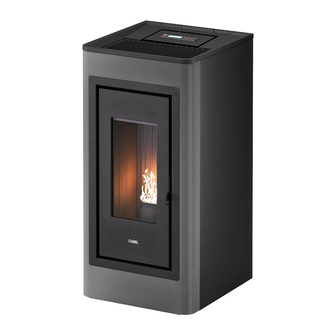
- Page 14 LEGEND Fig. 16 Exhaust fumes d.8 cm Hole combustion air inlet d.6 cm Ducting outlet d.8 cm Fig. 17 - GO 11 LEGENDA Fig. 17 Exhaust fumes d.8 cm Hole combustion air inlet d.6 cm Ducting outlet d.8 cm (FENICE Plus 11)
-
Page 15: Stove Door Removal/Installation
Fig. 18 - Eclipse 11 LEGENDA Fig. 18 Exhaust fumes d.8 cm Hole combustion air inlet d.6 cm Ducting outlet d.8 cm (FENICE Plus 11) STOVE DOOR REMOVAL/INSTALLATION DOOR REMOVAL For some operations (e.g.: side panel assembly and cleaning) you must remove the stove door. To remove the door: •... -
Page 16: Removal/Assembly Of The Frame
Fig. 21 - Remove the rear screws Fig. 22 - Remove the side panel Fig. 23 - . REMOVAL/ASSEMBLY OF THE FRAME (PRINCE 11 - PRINCE PLUS 11) To dissemble the frame, proceed as follows: • Push the frame upwards and release the teeth (see Fig. 24). •... -
Page 17: Removal/Assembly Of Lower Front Panel
Fig. 27 - Remove the front screws Fig. 28 - Remove the rear screws Fig. 29 - Remove the side panel REMOVAL/ASSEMBLY OF LOWER FRONT PANEL (FENICE 11 - FENICE PLUS 11) Proceed as follows to disassemble the front panel: •... - Page 18 Fig. 31 - Remove the rear screws Fig. 32 - Remove the side panel 6.10 REMOVAL/ASSEMBLY OF THE FRAME (KOBE 11 - KOBE PLUS 11) To dissemble the frame, proceed as follows: • Remove the cast iron top (see ). •...
-
Page 19: Removal/Assembly Of Side Panels (Spark 11)
Fig. 35 - Undo the screws Fig. 36 - Remove the front panel Fig. 37 - Unhook the rear panel • Unscrew the front screws (see ). • Remove the front panel (see ). • To assemble, proceed in reverse order. Fig. -
Page 20: Removal/Assembly Of The Frame (Go 11)
Remove the side panel (see ). To assemble, proceed in reverse order. Fig. 40 - Remove 6.13 REMOVAL/ASSEMBLY OF THE FRAME (GO 11) To dissemble the frame, proceed as follows: • Push the frame upwards and release the teeth (see Fig. 41). -
Page 21: Removal/Assembly Of The Frame (Eclipse 11)
Fig. 44 - Remove the rear screws Fig. 45 - Remove the side panel 6.15 REMOVAL/ASSEMBLY OF THE FRAME (ECLIPSE 11) To dissemble the frame, proceed as follows: • Remove grille (see Fig. 46). • Remove Top (see Fig. 47). •... -
Page 22: 6.16 Rear Or Upper Fume Exhaust
6.16 REAR OR UPPER FUME EXHAUST The connection of the fume exhaust can be at the back or on top. REAR EXHAUST Fig. 50 - Connection of the fume exhaust • Position the pipe as shown in Fig. 50. UPPER EXHAUST Fig. -
Page 23: 6.17 Concentric Pipe-Kit Assembly
6.17 CONCENTRIC PIPE-KIT ASSEMBLY The stove is designed to be connected to a concentric pipe by means of a dedicated kit. The upper exhaust with concentric pipe requires 1 kit code 5020002 (optional). To assemble the kit, proceed as follows: •... -
Page 24: 6.18.1 Ducting Solutions
6.18.1 Ducting solutions: SOLUTION A: ducting with the rear hot air outlet Fig. 63 - Diverter removal Fig. 64 - Insert pipe • Remove the air diverter (see Fig. 63). • The stove is ready to be ducted, position the pipe as shown in the photo (see Fig. 64). SOLUTION B: ducting with the upper hot air outlet. - Page 25 Fig. 68 - Block the flexible hose Fig. 69 - Connect pipe d.80 mm Fig. 70 - Fold the tabs • Block the flexible hose to the fan using the clamp supplied (see Fig. 68). • Connect the d.80 mm pipe supplied to the flexible hose (see Fig. 69). •...
-
Page 26: 6.19 Ducting Data
6.19 DUCTING DATA Fig. 73 - Ducting system example • If the stove is not fitted with ducting system, it provide a hot air capacity ranging from a minimum of 44 m /h to a maximum of 86 m /h with a temperature ranging between 95°C and 140°C. •... -
Page 27: 6.21 Connection To The External Thermostat
Fig. 74 - Electric socket with master switch Fig. 75 - Plug connected • Do not use extension cables. • If the feeder cable is damaged, it must be replaced by an authorized technician. • When the stove is not going to be used for a long period of time, it advisable to remove the plug from the socket on the wall. •... -
Page 28: Special Maintenance
Fig. 77 - Casing removal DATA Stove depression - 25 Pa - 120°C 44 Pa - 138°C 57 Pa - 165°C 64 Pa - 185°C 70 Pa - 200°C temperature 11 kW NB: for good combustion, the depression values must be between ± 5 Pa and the temperature values between ± 10°C. SPECIAL MAINTENANCE INTRODUCTION For a long working life of the stove, have a periodic cleaning of the stove as described in the following paragrafs. -
Page 29: Fume Conduit Cleaning
Fig. 78 - Remove the burning pot Fig. 79 - Vacuum out the ash Fig. 80 - Remove the cap • Clean with a pipe cleaner and suction any ash accumulated inside (see Fig. 81 and Fig. 82). • After cleaning, repeat the operation in reverse making sure the gasket is intact and efficient: if necessary, have it replaced by an authorised technician. -
Page 30: Fume Passage Cleaning
FUME PASSAGE CLEANING Every end-of-season (or every 2000 hours of operation) it is necessary to clean the fume passages. • Remove the door (see the dedicated chapter). • Undo the hex head screws that block the cast-iron tiles of the hearth, on both sides (see Fig. 84). •... -
Page 31: Fume Fan Cleaning
FUME FAN CLEANING Clean every the year the fume fan from ash or dust which can cause a blade unbalance and a greater noise. • Open the door and release the panel under the door (see dedicated chapter). • Remove the inspection cap (see Fig. 91). •... -
Page 32: In Case Of Anomaly
IN CASE OF ANOMALY PROBLEM SOLVING Before of every Authorized Technician intervention, the same Technician has the duty to check if the parame- ters of the mother board correspond to those of the table you own. In case of doubts regarding the use of the stove, please contact ALWAYS the Authorized Technician on order to avoi irreparable damages! PROBLEM CAUSE... - Page 33 PROBLEM CAUSE SOLUTION INTERVENTION Empty hopper Full the hopper. Auger blocked by a foreign object (for Clean the auger. example nails) The fire extinguish Bad quality pellets Try other types of pellets. and the stove stops Pellet drop value too Adjust the pellet loading.
- Page 34 PROBLEM CAUSE SOLUTION INTERVENTION The stove is at its Ambient temperatu- The stove is at its minimum value. Increase the desired ambient highest power but re reached. temperature. does not heat up. Stove running and display showing Reached fume outlet The stove runs at minimum.
-
Page 35: Technical Datas
TECHNICAL DATAS REPAIR INFORMATION Now we give some instructions for the Authorized Technician to take into consideration to have access to stove mechanical com- ponents. • For fuse replacement in the electric socket which stands on the back of the stove, extract the fuses to change with the aid of a screwdriver for opening the shutter (see Fig. -
Page 36: Features
FEATURES DESCRIPTION PRINCE 11 T1 KOBE 11 T1 FENICE 11 T1 WIDTH 51,5 cm 51,6 cm 56,9 cm DEPTH 54,7 cm 55 cm 53 cm HEIGHT 109,9 cm 109,6 cm 109cm WEIGHT 109 kg 111 kg 130 kg INTRODUCED THERMIC POWER (Min/Max) 3,3 - 11,6 kW 3,3 - 11,6 kW 3,3 - 11,6 kW... - Page 37 PRINCE PLUS 11 FENICE PLUS 11 DESCRIPTION KOBE PLUS 11 T1 WIDTH 51,5 cm 51,6 cm 56,9 cm DEPTH 54,7 cm 55 cm 53 cm HEIGHT 109,9 cm 109,6 cm 109cm WEIGHT 112 kg 114 kg 133 kg INTRODUCED THERMIC POWER (Min/Max) 3,3 - 12 kW 3,3 - 12 kW 3,3 - 12 kW...
- Page 38 DESCRIPTION INDACO 11 T1 SPARK 11 T1 WIDTH 47,7 cm 47,6 cm DEPTH 55,2 cm 54,8 cm HEIGHT 108 cm 108 cm WEIGHT 114 kg 108 kg INTRODUCED THERMIC POWER (Min/Max) 3,3 - 11,6 kW 3,3 - 11,6 kW NOMINAL THERMIC POWER (Min/Max) 3 - 10,5 kW 3 - 10,5 kW EFICIENCY (Min/Max)
- Page 39 DESCRIPTION GO 11 T1 ECLIPSE 11 T1 WIDTH 51,5 cm 58.2 cm DEPTH 56 cm 54.6 cm HEIGHT 110 cm 108 cm WEIGHT 112 kg 133 kg INTRODUCED THERMIC POWER (Min/Max) 3,3 - 12 kW 3,3 - 12 kW NOMINAL THERMIC POWER (Min/Max)
- Page 40 Rev. 00- 2023 CADEL srl www.cadelsrl.com 31025 S. Lucia di Piave - TV www.free-point.it Via Martiri della Libertà, 74 - Italy www.pegasoheating.com Tel. +39 0438 1520200...
Need help?
Do you have a question about the GO 11 and is the answer not in the manual?
Questions and answers