Advertisement
Available languages
Available languages
Quick Links
Montageanleitung
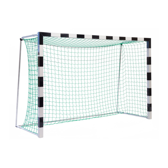
Tor mit Stahl-Netzbügel klappbar
Alu-Guss Eckverbinder
Handballtor: 3,00 x 2,00 m
Art.-Nr.: 1150911 - freistehend
Art.-Nr.: 1136513 - in Bodenhülsen
Fußballtor: 5,00 x 2,00 m
Art.-Nr.: 1136119 - freistehend
Vielen Dank, dass Sie sich für ein Sport-Thieme - Produkt entschieden haben.
Damit Sie viel Freude an diesem Produkt haben, erhalten Sie im Folgenden
wichtige Hinweise für Ihre Sicherheit sowie den Gebrauch und die Wartung des
Gerätes. Lesen Sie bitte diese Anleitung vollständig durch, bevor Sie mit der
Montage bzw. Nutzung beginnen.
1. Lieferumfang:
Bitte prüfen Sie den nachfolgend angegebenen Inhalt auf Vollständigkeit bevor
Sie mit dem Aufbau beginnen.
Die angegebenen Mengen in den Stücklisten beziehen sich auf 1 Stück Tor.
Bei paarweiser Lieferung ist jeweils die doppelte Menge enthalten. Die in
der Montageanleitung abgebildeten Farbtöne der Profile sind nur Beispiele.
Die Farbtöne können von denen der gelieferten Profile abweichen.
Stück
Beschreibung
Stahl-Bodenrohr, verzinkt, Ø ¾"
1
1
Latte, Profil 80 x 80 mm
2
Pfosten, Profil 80 x 80 mm
1
Sechskant-Winkelschraubendreher SW6, DIN 911, Länge ca. 470 mm
(nur bei Tor in Bodenhülse)
1
Tornetz (nur bei Mini-Handballtor Art.-Nr.: 225 - ohne Abbildung)
1
Advertisement

Subscribe to Our Youtube Channel
Related Manuals for Sport-thieme 1150911


Summary of Contents for Sport-thieme 1150911
- Page 1 Fußballtor: 5,00 x 2,00 m Art.-Nr.: 1136119 - freistehend Vielen Dank, dass Sie sich für ein Sport-Thieme - Produkt entschieden haben. Damit Sie viel Freude an diesem Produkt haben, erhalten Sie im Folgenden wichtige Hinweise für Ihre Sicherheit sowie den Gebrauch und die Wartung des Gerätes.
- Page 2 Stück Beschreibung Netzbügel Stück Beschreibung Alu-Guss-Eckverbinder Pfostenverschlusskappe Stahl-Scharnier/Winkel für oben (1x rechts, 1 x links) Stahl-Scharnier für unten (1x rechts, 1 x links) Stahl-Strebe Zubehörbeutel Stück Beschreibung Folgende Teile nur für Art.-Nr. 1136513 Tor in Bodenhülse Bodenhülse, Länge 300 mm Abdeckkappe für Bodenhülsen...
- Page 3 Inhalt Zubehörbeutel: Stück Beschreibung Netzhalter schwarz Netzhalter orange Gewindehülse mit Gewinde M8, Alu-Rundrohr 20 x 5 mm, Länge 40 mm Einsteckmutter, 40 mm, Gewinde M8 Handrad M8 Kabelbinder Steckerstift Sechskantschraube M8 x 90mm, DIN 931 Sechskantschraube M8 x 12mm, DIN 933 Sicherungs-Senkschraube mit Innensechskant M8 x 20mm, DIN 7991 Zylinderschraube mit Innensechskant M8 x 16mm, DIN 912 Sechskant-Sicherungsschraube, M8 x 16mm, DIN 933...
- Page 4 a) Montage Latte/Pfosten: Die Latte und die beiden Pfosten flach auf den Boden legen, sodass die Nut nach oben zeigt und die Gehrungen aneinander liegen. An jeder Torrahmenecke 5 Stck. Alu-Einsteckmuttern Gewinde M8, Länge 40mm, in die Nut der Netzhakenschiene stecken (jeweils 2 Stck. am Pfosten und 3 Stck.
- Page 5 Im nächsten Montageschritt Pfosten und Latte an der Außenecke zusammen- schieben. Latte und Pfosten ausrichten. An der Außenseite der Ecke 2 Stck. Sicherungs-Senkschrauben DIN 7991, M8 x 20mm einschrauben (siehe Fotos unten) und anschließend alle Schrauben fest anziehen. Ecke zusammenschieben und ausrichten Hinweis: Aufgrund von Fertigungstoleranzen der Alu-Gusseckverbinder kann es in seltenen Fällen vorkommen, dass sich die Ecke nicht exakt ausrichten lässt.
- Page 6 Montage Stahl-Scharnier unten – freistehendes Tor: Art.-Nr. 1150911, 1136119: Unteres Stahl-Scharnier mit den Bohrungen deckungsgleich über den vorge- sehenen Löchern unten am Pfosten auflegen. Die offene Seite des U-Profils muss dabei zur Torinnenseite zeigen (siehe Foto unten links und rechts).
- Page 7 d) Montage Pfostenverschlusskappe: Die Pfostenverschlusskappe in das offene Ende des Pfostens stecken (siehe Foto unten links). Die Kunststoffstege der Verschlusskappe durch die werkseitig angebrachten Bohrungen im Pfosten mit einem 1,5 mm Bohrer aufbohren. Danach die Steckerstifte mit einem Hammer/Gummihammer eintreiben (siehe Foto unten rechts). Vorbereitung Montage Netzbügel: Durch die Bohrung im Netzbügel je von innen nach außen 1 Stck.
- Page 8 Montage Netzbügel oben: Den Netzbügel in die Scharnierhalter oben und unten stecken und die Netzbügel-Strebe auf die Latte stellen. Die ange- schrägte Seite des Netzbügels muss nach außen zeigen (siehe 2. Foto unten rechts). Dann am Eckpunkt Latte/Pfosten 1 Stck. Sechskantschraube M8 x 50mm, DIN 932 von unten durch die Bohrungen des Scharniers stecken, 1 Stck.
- Page 9 Montage Netzbügel unten - Tor freistehend: Art. Nr. 1150911, 1136119: 1 Stck. Senkschraube DIN 953, M8 x 50mm von unten durch die Bohrungen von Scharnier und Netzbügel stecken, 1 Stck. selbstsichernde Mutter DIN 985, M8 aufschrauben und festziehen (siehe nachfolgende Fotos). Danach auch die Schrauben am oberen Scharnier fest anziehen.
- Page 10 i) Montage Bodenrohr: 1 Stck. Sechskantschraube DIN 931, M8 x 90 durch die Gewindehülse aus Alu-Rundrohr 40 mm stecken (siehe Foto unten links). Dann die Gewindehülse in das Bodenrohr einschieben, sodass die Bohrungen in der Gewindehülse und dem Bodenrohr deckungsgleich sind (siehe Foto unten Mitte).
- Page 11 Abstand). Wir empfehlen folgende gleichmäßige Verteilung der Netzhalter: Netzhalter Torgröße Art.-Nr. Gesamt Latte je Pfosten 1150911 3,00 x 2,00m 1136513 3,00 x 2,00m 1136119 5,00 x 2,00m Alle zusätzlich im Lieferumfang enthaltenen Netzhalter für die weiteren An- schlüsse verwenden. Im Bereich des Netzbügels die mitgelieferten orangenen Netzhalter (Eckbereich Latte /Posten jeweils 2 Stück, Pfosten unten jeweils 1 Stück) durch die...
- Page 12 b) Zur Befestigung der oberen und unteren Spannschnur ein Ende der Schnur jeweils an den bereits montierten Gewinderingösen befestigen und gut ver- knoten. Schnur durch die Netzmaschen ziehen und an der 2. Gewindering- öse befestigen und ebenfalls gut verknoten. Überstehende Schnurenden abschneiden (siehe Beispiel Fotos unten).
- Page 13 5. Einbau der Bodenhülsen: a) Für Handballtore mit einem Innenmaß von 3,00 x 2,00 m beträgt der Abstand der Bodenhülse 3,08 m (Mitte Hülse – Mitte Hülse = Achsabstand). b) Mitgelieferte Bodenhülsen gemäß Einbauskizze einbetonieren - Fundamentgröße 800 x 800 x 800 mm (L x B x H). c) Verwenden Sie beim Einbetonieren keine Schnellabbinde- oder Frostschutz- mittel, da diese Zusätze zu Beschädigungen an der Bodenhülse führen können.
- Page 14 7. Prüfung und Instandhaltung: (nach EN 16579) a) Eine routinemäßige Sichtprüfung sollte vor jeder Verwendung durchgeführt werden. b) Eine operative Prüfung sollte mindestens alle 6 Monate oder je nach Herstellerangaben oder gemäß / nach nationalen Verordnungen / Normen öfter erfolgen. c) Eine Hauptprüfung sollte mindestens einmal jährlich oder je nach Herstellerangaben oder gemäß...
-
Page 15: Scope Of Delivery
1136513 - in ground sockets Soccer goal: 5.00 x 2.00 m Cat.-no.: 1136119 - free standing Thanks for choosing Sport-Thieme equipment. In order to enjoy this product please note the following instructions for safety, use and maintenance before assembly. 1. Scope of delivery: Please check the following content before assembly. - Page 16 Piece Description Net hoop Piece Description Aluminium cast corner joint Upright cap Upper steel hinge (1 right, 1 left),galvanized Lower steel hinge (1 right, 1 left),galvanized Steel brace, galvanized Accessories Piece Description Following parts only for catalogue no. 1136513 – goal in ground sockets Ground socket, length 300 mm Cap for ground sockets...
- Page 17 Accessories: Piece Description Net holder black Net holder orange Bushes with thread M8, of aluminium round tube 20 x 5 mm, length 40 mm Nut, 40 mm, thread M8 Hand wheel M8 Plastic holder Plug pin Hexagon screw M8 x 90mm, DIN 931 Hexagon screw M8 x 12mm, DIN 933 Hexagon socket screw M8 x 20mm, DIN 7991 Hexagon socket screw M8 x 16mm, DIN 912...
- Page 18 a) Assembly of crossbar/uprights: Lay crossbar and uprights on the ground, groove facing upwards and mitres joining. Stick at each goal frame corner 5 nuts with thread M8, length 40 mm into the groove of the net hook rail (push 2 into the upright and 3 into the crossbar, see 1 picture bottom left).
- Page 19 Then join upright and crossbar at the external edge and adjust upright and crossbar. Screw 2 hexagon socket screws DIN 7991, M8 x 20mm in the external corner and tighten all screws (see bottom pictures). join and adjust corner Advice: Due to production tolerances of the aluminium cast corner joints problems during adjustment of corners may possibly occur.
- Page 20 Assembly of lower steel hinge – upright of free standing goal: Cat.-no.: 1150911, 1136119: Place lower steel hinge over the holes provided at the bottom of the upright, the open side of the U-profile facing to the goal inside (see pictures bottom left and right). Stick from the inside 4 hexagon socket screws DIN 912, M8 x 16mm with hexagon screwdriver SW6, length 120mm through holes of upright and steel hinge.
- Page 21 d) Assembly of caps: Stick caps in the open ends of uprights (see picture bottom left). Bore them with drill 1.5 mm through the holes provided in the uprights. Then fix plug pins with a hammer/mallet (see picture bottom right). e) Assembly of net hoop: Stick from the inside 1 hexagon screw DIN 933, M8 x 40 through the hole of the net hoop.
- Page 22 f) Preparation assembly of net hoop on the top: Now push from the bottom net hoop brace (see picture bottom left). Stick net hoop into hinge parts and lay net hoop brace on the crossbar, the chamfered side of the net hoop facing to the outside (see 2 picture bottom right).
- Page 23 Assembly net hoop on the bottom – goal free standing: Cat.-no.: 1150911, 1136119: Fix net hoop at the lower hinge. Stick from the bottom 1 flat head screw DIN 953, M8 x 50mm through holes of hinge and net hoop, screw and tighten 1 self-locking nut DIN 985, M8 (see pictures at the buttom).
- Page 24 i) Assembly of ground tube: Stick hexagon screw DIN 931, M8 x 90 through bush of aluminium tube (see picture bottom left). Then push bush into the ground tube (see picture bottom mid) and screw hexagon screw DIN 933, M8 x 12mm through holes of bush and ground tube.
- Page 25 We recommend the following distribution of net holders: Net holders Size Cat.-no.: Total crossbar uprigths 1150911 3,00 x 2,00m 1136513 3,00 x 2,00m 1136119 5,00 x 2,00m Use all the other included net holders for the other connections. To fix net in the area of the net hoops, insert the orange net holders (corner crossbar/uprights each 2 pieces, upright bottom each 1 piece) through the holes of the brackets/holders and screw them into the groove (see picture bottom).
- Page 26 b) Fix ends of upper and lower tensioning rope at the mounted ring nuts. Cut off protruding rope ends (see bottom picture). c) Fix net with plastic holders in the bottom part of net hoops. Cut off protruding ends of plastic holders (see picture bottom right). 4.
- Page 27 5. Assembly of the ground sockets: For handball gates with a size of 3,00 x 2,00 m the distance of the ground sockets must be 3,08 m (middle socket – middle socket = center distance). b) Concrete ground sockets according to the sketch. Foundation dimensions: 800 x 800 x 800 mm.
-
Page 28: Inspection And Maintenance
7. Inspection and maintenance: (check according to EN 16579) a) Visual inspections should routinely be realized before each use. b) Functional inspections should take place at least every six months or according to manufacturer’s instructions/national regulations/standard specifications. c) A general inspection should be realized at least once a year or according to manufacturer’s instructions/national regulations/standard specifications.
Need help?
Do you have a question about the 1150911 and is the answer not in the manual?
Questions and answers