Table of Contents
Advertisement
Available languages
Available languages
ZoellerAtHome.com
Zoeller
is a registered trademark
®
of Zoeller Co. All Rights Reserved.
ATTACH YOUR RECEIPT HERE
Serial Number
Questions, problems, missing parts? Before returning to your retailer, call our customer
service department at 1-800-584-8089, 7:30 a.m. - 5:00 p.m., EST, Monday - Friday.
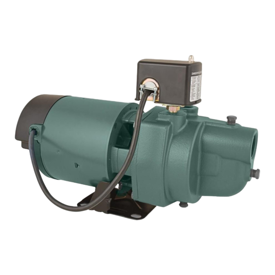
SHALLOW WELL JET PUMP
Purchase Date
1
CAST IRON
MODEL #1461-0006
Español p. 21
IL1102
024987 D
Advertisement
Table of Contents

Related Manuals for Zoeller 1461-0006


Summary of Contents for Zoeller 1461-0006
- Page 1 ZoellerAtHome.com MODEL #1461-0006 Español p. 21 Zoeller is a registered trademark ® of Zoeller Co. All Rights Reserved. IL1102 ATTACH YOUR RECEIPT HERE Purchase Date Serial Number Questions, problems, missing parts? Before returning to your retailer, call our customer service department at 1-800-584-8089, 7:30 a.m. - 5:00 p.m., EST, Monday - Friday.
-
Page 2: Product Specifications
VOLTAGE HZ ROTOR AMPS 0 FT. 5 FT. 15 FT. 25 FT. AMPS 1461-0006 115/230 13/6.5 36.0/18.0 SAFETY INFORMATION Please read and understand this entire manual before attempting to assemble, operate, or install the product. • NOTE: Pumps with the “UL” Mark and pumps with the “US” mark are tested to UL Standard UL778. - Page 3 • ELECTRICAL SHOCK ALERT. Wire motor to correct supply voltage. See motor nameplate and wiring diagrams and check voltage of power supply. • ELECTRICAL SHOCK ALERT. Unit must be securely and adequately electrically grounded. This can be accomplished by wiring the unit to a ground metal-clad raceway system or by using a separate ground wire connected to the bare metal of the motor frame or other suitable means.
-
Page 4: Package Contents
PACKAGE CONTENTS Description Quantity CAUTION Pump IL1102 PREPARATION Before beginning installation of product, make sure all parts are present. If any part is missing or damaged, do not attempt to assemble the product. Compare parts to package contents list. Estimated Installation Time: 2 hours. Tools Required for New Installation (not included): pipe wrench, pliers, Phillips screwdriver, pipe clamp, 2-step PVC glue system (primer and sealer), thread tape, tire gauge and tire pump Parts Required for New Installation (not included): well seal, 1-1/4 in. - Page 5 2. Jet pumps can also be used with dug wells, 1 in. Discharge Discharge Pipe driven wells, or with cisterns or lakes. Check to Home Valve Suction Lift 1-1/4 in. Suction Pipe 25 ft. Pipe Support Water Level Drive Point IL1472 Ventilation - Ventilation and drainage must be provided to prevent damage to the motor from heat and moisture.
- Page 6 WELL TO PUMP CONNECTION (SUCTION PIPE) CAUTION: Dry-fit entire assembly to ensure proper fit before gluing or taping parts. CAUTION: Follow all proper gluing procedures as specified by the glue manufacturer. Always glue in a vertical direction whenever possible to prevent glue from dripping inside pipe or fittings CAUTION: Use pipe tape and pipe paste compound on all male threads.
- Page 7 3b. For driven wells, a check valve is required at the top of the well to maintain prime. Flow arrow must point toward pump. Flow Pump Arrow IL1359 4. Finish the connection to your well with additional pipe and fittings as needed. IL1360 PUMP TO PRESSURE TANK CONNECTION (DISCHARGE PIPE) 1.
- Page 8 2. Install a 1 x 1 x 1 in. galvanized tee fitting. IL1362 3. Install a 1 in. MPT x 1/4 in. FPT galvanized bushing and pressure gauge (optional), or a pipe plug. Do not tighten, as you will prime your pump later at this location IL1363 4.
- Page 9 2. Use a pressure gauge to ensure it’s set to 18 PSI. Pressure a. Use a tire pump to adjust the PSI to 18 PSI gauge Air release valve b. If water leaks from the air release valve, Set to replace the pressure tank.
- Page 10 4. Attach a 1 in. pipe (not included) to the reducer bushing. Install an optional 1 in. union (not included) and continue with pipe and 1 in. x 1 in. x 1 in. tee (not included). Glue Union 1 in. pipe 5.
- Page 11 PUMP ELECTRICAL CONNECTIONS WIRE SIZE CHART WARNING: Recommended Copper • Always disconnect pump from electricity Wire and Fuse Sizes Distance before performing any work on the motor. Single Phase Motors from Motor to • Under-sized wiring can cause motor failure Meter 3/4 HP and even fire.
- Page 12 2. Insert an electrical wire strain relief into the opening in the side of the pressure switch closest to the motor. IL1372 3. Thread the cable from the pump motor Wire from through the strain relief into the pressure motor switch cavity and tighten both screws on the strain relief.
- Page 13 6. Insert an electrical wire strain relief into the opening in the opposite side of the pressure Wire from switch. motor Strain relief Pressure switch IL1376 7. Thread the cable from the power supply Wire from Wire from through the strain relief and tighten both power motor supply...
- Page 14 LR90197 starwatersystems.com UL Std. No. 778 ENCLOSURE 3 ES05S Pump: Rev: To change from 115V to 230V 98L105 Motor: 1. The motor of this pump is dual voltage and can run on either 115V or 230V. In general, Volts 115/230 S.F.
- Page 15 PUMP PRIMING & STARTUP CAUTION: All pumps must be primed Priming Plug (filling the cavity with water) before they are with Pressure Gauge first operated. This may take several gallons of water, as the suction line will be filled in addition to the pump cavity.
- Page 16 5. Thread in priming plug and then open optional ball valve if installed by turning handle to line up with the pipe. IL1353 6. PRIMING NOTE: Several priming attempts may be necessary, depending on the length of suction pipe and location of check valve if a well point is being used.
-
Page 17: Care And Maintenance
IMPORTANT: If the pump fails to prime within five minutes: Turn power off at the breaker box and check all pipe connections for leaks. All connections must be water and air tight in order for pump to operate. All piping from the well to the pump should slope slightly upward with no sagging. -
Page 18: Quick Trouble-Shooting Checklist
QUICK TROUBLE-SHOOTING CHECKLIST Please review the following troubleshooting questions before returning a pump as defective. If you have any questions, please call Customer Service at (800) 584-8089. 1. Check date code to make sure pump is within warranty period. Date code is the month and the MODEL LIQUID PUMP LR90197... -
Page 19: Troubleshooting
TROUBLESHOOTING PROBLEM POSSIBLE CAUSE CORRECTIVE ACTION Little or no 1. Casing not initially filled with water 1. Fill pump casing discharge 2. Suction lift too high, or too long 2. Move pump closer to water source 3. Hole or air leak in suction line 3. -
Page 20: Warranty
WARRANTY This product is warranted for two years from the date of purchase. Subject to the conditions hereinafter set forth, the manufacturer will repair or replace to the original consumer any portion of the product which proves defective due to defective materials or workmanship. To obtain warranty service, contact the dealer from whom the product was purchased. - Page 21 ZoellerAtHome.com HIERRO FUNDIDO Zoeller es una marca registrada de ® MODELO #1461-0006 Zoeller Co. Todos derechos reservados. IL1102 ADJUNTE SU RECIBO AQUÍ Fecha de compra Número de serie ¿Preguntas, problemas, partes faltantes? Antes de acudir al minorista, llame a nuestro departamento de servicio al cliente al 1-800-584-8089, de lunes a viernes de 7:30 a.m.
-
Page 22: Especificaciones Del Producto
MODELO DESCARGA DE 20 PSI MÁXIMO BLOQUEADO 0 PIES 5 PIES 15 PIES 25 PIES 1461-0006 115/230 13/6.5 36.0/18.0 INFORMACIÓN DE SEGURIDAD Lea y comprenda completamente este manual antes de intentar ensamblar, usar o instalar el producto. • NOTA: Las bombas con la marca “UL” y con la marca “US” se prueban para cumplir los estándares de UL UL778. - Page 23 ALERTA DE DESCARGA ELÉCTRICA. No pliegue el cable de alimentación ni permita que entre en contacto con aceite, grasa, superficies calientes ni sustancias químicas. • ALERTA DE DESCARGA ELÉCTRICA. Conecte el motor al voltaje de alimentación correcto: Consulte la placa de datos y los diagramas de cableado del motor y revise el voltaje del suministro de electricidad.
-
Page 24: Contenido Del Paquete
CONTENIDO DEL PAQUETE DESCRIPCIÓN CANTIDAD CAUTION Bomba IL1102 PREPARACIÓN Antes de comenzar a instalar el producto, asegúrese de tener todas las piezas. Compare las piezas con la lista del contenido del paquete. No intente ensamblar el producto si falta alguna pieza o si estas están dañadas.ompare las piezas con la lista del contenido del paquete. - Page 25 2. Las bombas de chorro también pueden Válvula Tubería de Descarga a de control usarse en pozos excavados, pozos de hinca descarga la casa de 3/4 pulg o con cisternas o lagos. Elevación de succión Tubería de succión de 1-1/4 pulg 7,62 m máx.
- Page 26 CONEXIÓN DESDE EL POZO HACIA LA BOMBA (TUBERÍA DE SUCCIÓN) PRECAUCIÓN: Ajuste completamente el ensamble para asegurarse de obtener un ajuste adecuado antes de unir las piezas definitivamente. PRECAUCIÓN: Siga todos los procedimientos adecuados para unir como lo especifica el fabricante de adhesivo.
- Page 27 3b. En los pozos hincados, se requiere una válvula de retención en la parte superior del pozo para mantener el cebado. La flecha de Flecha flujo debe apuntar hacia la bomba. Bomba de flujo IL1359 4. Complete la conexión del pozo con las tuberías y los conectores adicionales según sea necesario.
- Page 28 2. Instale un conector galvanizado en “T” de 2.5 x 2.5 x 2.5 cm (1 x 1 x 1 pulg.). IL1362 3. Instale una rosca macho de 2.5 cm (1 pulg.) x rosa hembra de 0.6 cm (1/4 pulg.) y un manómetro (opcional), o un tapón para tubos.
- Page 29 2. Use un indicador de presión para asegurarse de que esté en 18 psi. Indicador Válvula de a. Use una bomba para neumáticos para de presión descarga de aire ajustar los psi en 18 psi. Establezca b. Si el agua se filtra por la válvula de en 18 psi descarga de aire, reemplace el tanque de presión.
- Page 30 4. Conecte un tubo (no incluido) de DN25 (1 pulg. NPT) al buje reductor. Instale una unión opcional (no incluida) de 2.5 cm (1 pulg.) y continúe con el tubo y la “T” (no Adhesivo incluida) de 2.5 x 2.5 x2.5 cm (1 x 1 x 1 Unión pulg.).
- Page 31 BOMBEO DE LAS CONEXIONES ELÉCTRICAS TABLA DE TAMAÑOS DE CABLES ADVERTENCIA: Tamaños de cables de cobre • Siempre desconecte la bomba de la fuente y fusibles recomendados de energía antes de llevar a cabo cualquier Distancia desde el Motores de fase única motor al medidor trabajo en el motor.
- Page 32 2. Inserte un pasacables de cables eléctricos en la abertura del lado del presostato más cercano al motor. IL1372 3. Pase el cable desde el motor de la bomba Cable desde a través del pasacables hasta dentro la el motor cavidad del presostato y apriete los dos tornillos del pasacables.
- Page 33 6. Inserte un pasacables de cables eléctricos en la abertura del lado opuesto del presostato. Cable desde el Aliviador motor tensión Interruptor de presión IL1376 7. Pase el cable desde la fuente de alimentación a través del pasacables y apriete los dos tornillos del pasacables. No Cable desde el Cable aplaste el cable.
- Page 34 LR90197 starwatersystems.com UL Std. No. 778 ENCLOSURE 3 ES05S Pump: Rev: Para cambiar de 115 V a 230 V 98L105 Motor: 1. El motor de esta bomba es de doble voltaje y puede funcionar a 115 V o 230 V. En Volts 115/230 S.F.
- Page 35 CEBADO Y PUESTA EN MARCHA DE LA BOMBA PRECAUCIÓN: Se deben cebar todas las Tapón de bombas. Para esto, llene la cavidad con agua cebado con manómetro antes de hacerlas funcionar por primera vez. Se necesitarán varios litros de agua ya que debe llenarse la línea de succión y la cavidad de la bomba.
- Page 36 5. Enrosque el tapón de cebado y luego abra la válvula de bola opcional, si está instalada, girando la manija para alinearla con la tubería. IL1353 6. NOTA DE CEBADO: pueden ser necesarios varios intentos de cebado, dependiendo de la longitud de la tubería de succión y la ubicación de la válvula de retención, si se Válvula de retención está...
-
Page 37: Cuidado Y Mantenimiento
IMPORTANTE: Si la bomba no se ceba en los siguientes cinco minutos: Desconecte la energía en la caja de disyuntores y compruebe todas las conexiones de tuberías en busca de fugas. Todas las conexiones deben ser herméticas para que la bomba funcione. Todas las tuberías del pozo a la bomba deben inclinarse ligeramente hacia arriba sin deformaciones. - Page 38 LISTA DE VERIFICACIÓN RÁPIDA PARA SOLUCIÓN DE PROBLEMAS Revise las siguientes preguntas de solución de problemas antes de devolver una bomba como defectuosa. Si tiene alguna pregunta, llame a Servicio al Cliente al (800) 584-8089. 1. Verifique el código de fecha para asegurarse de que la bomba está...
-
Page 39: Solución De Problemas
SOLUCIÓN DE PROBLEMAS PROBLEMA CAUSA POSIBLE ACCIÓN CORRECTIVA La descarga 1. El entubado no está inicialmente relleno 1. Llene el entubado de la bomba es mínima con agua o no hay 2. La elevación de succión es demasiado 2. Acerque la bomba al suministro de agua descarga alta o demasiado larga 3. -
Page 40: Piezas De Repuesto
GARANTÍA Este producto se garantiza por un período de dos años a partir de la fecha de fabricación. Sujeto a las condiciones indicadas a continuación, el fabricante se compromete a reparar o reemplazar al consumidor original cualquier parte del producto que resulte defectuosa debido a defectos de materiales o mano de obra. Para obtener el servicio de garantía, póngase en contacto con el distribuidor al que le compró...
Need help?
Do you have a question about the 1461-0006 and is the answer not in the manual?
Questions and answers