Advertisement
Quick Links
Installation & Maintenance Instructions
NOTICE:
See
separate
maintenance instructions for information on:
Solenoid Temperature, Cause of Improper Operation and
Coil Replacement.
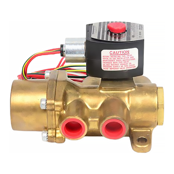
DESCRIPTION
Series 8344 valves are packless, solenoid pilot controlled, heavy duty, 4-way
valves with forged brass valve bodies and poppet type main discs. The main
discs are power driven in both directions by line pressure. No return springs
are required. Valves may be provided with a general purpose/watertight,
open frame, or watertight/explosionproof solenoids.
OPERATION
Solenoid De-Energized: Flow is from Pressure P to Cylinder A and from
Cylinder B to Exhaust E.
Solenoid Energized: Flow is from Pressure P to Cylinder B and from Cylinder
A to Exhaust E.
Minimum on time for valve is 0.3 seconds on air service and 1.0 seconds on
liquids
IMPORTANT: Minimum operating pressure differential is 10
psi on air, gas or water and 25 psi on hydraulic oil (300 S.S.U.).
FLOW DIAGRAM for Single Solenoid
De-Energized
Cyl. B
Cyl. A
Press. Exh.
P
E
Manual Operator (optional feature)
Manual operator allows manual operation when desired or during an electrical
power outage. To engage manual operator (open the valve), turn lever clockwise
until it hits a stop. Valve will now be in the same position as when the solenoid
is energized.
To disengage manual operator (close the valve) turn lever
counterclockwise until it hits a stop.
CAUTION:
For valve to operate electrically, manual
operator lever must be fully rotated counterclockwise.
SPEED/FLOW CONTROL-METERING DEVICE
Speed/flow control valves (2) may be added to allow full unrestricted flow in
one direction and controlled flow in the opposite direction. These valves
must be in the A" and/or B" cylinder piping, between the solenoid valve and
the cylinder.
IMPORTANT: Do not install the speed control or any other
restrictive device in either the pressure (inlet) connection or
the exhaust (outlet) connection of the valve. Restricting either
of these lines may cause valve malfunction.
50 Hanover Road, Florham Park, New Jersey 07932 www.ascovalve.com
4-WAY HEAVY DUTY SINGLE SOLENOID VALVES
1/4I, 3/8I, 1/2I, 3/4I OR 1I NPT
1/4I, 3/8I OR 3/4I ORIFICE
solenoid
installation
and
Wiring,
Energized
Cyl. B
Cyl. A
Press. Exh.
P
E
locking pawl
bonnet
body gasket
FREE FLOW
METERED FLOW
INSTALLATION
Check nameplate for correct catalog number, pressure, and service. Never
apply incompatible fluids or exceed pressure rating of the valve. Installation
and valve maintenance to be performed by qualified personnel.
Positioning
This valve is designed to perform properly when mounted in any position.
However, for optimum life and performance, the operator should be
mounted vertically and upright to reduce the possibility of foreign matter
accumulating in the pneumatic operator.
Piping
Connect piping or tubing to valve according to markings on valve body. Refer
to flow diagrams. Apply pipe compound sparingly to male pipe threads only.
If applied to valve threads, the compound may enter the valve and cause
operational difficulty. Avoid pipe strain by properly supporting and aligning
piping. When tightening the pipe, do not use valve or pneumatic operator as
a lever. Locate wrenches applied to valve body or piping as close as possible
to connection point.
To insure proper operation of the valve, the pressure and exhaust lines must
be full area without restriction. A minimum differential pressure as stamped
on the nameplate must be maintained between pressure and exhaust at the
moment of shifting. Air reservoirs must have adequate capacity to maintain
this minimum pressure during shifting. To check pressure during shifting,
install a pressure gauge in the pressure piping as close to the valve as possible.
Cylinder B"
Wiring Diagram for
Single Solenoid
Power Line
Pressure guage
location
Pressure P"
Exhaust E"
MAINTENANCE
WARNING: To prevent the possibility of death,
personal injury or property damage, depressurize
valve (main and auxiliary pressure lines), and vent
fluid to a safe area before servicing the valve.
NOTE: It is not necessary to remove the valve body from the pipeline for repairs.
Page 1 of 4 (Section 1 of 2)
E176963
SERIES
8344
I&M No.V7544 -Sec. 1
(Section 1 of 2)
metering knob stem
stem gasket
spring
valve body
disc
Cylinder A"
Location of Metering
Devices when used
Full size piping without
restrictions must be
used on pressure and
exhaust lines.
All Rights Reserved.
Advertisement

Related Manuals for Asco 8344


Summary of Contents for Asco 8344
-
Page 1: Installation And
Coil Replacement. spring valve body disc DESCRIPTION Series 8344 valves are packless, solenoid pilot controlled, heavy duty, 4-way FREE FLOW METERED FLOW valves with forged brass valve bodies and poppet type main discs. The main INSTALLATION discs are power driven in both directions by line pressure. No return springs Check nameplate for correct catalog number, pressure, and service. -
Page 2: Temperature Limitations
For 3/8I and 1/2I NPT valve with 3/8Iorifice, torque locknut to remove core assembly with spring, core guide and body gasket. 125 ± 10 in-lbs [14,1 ± 1,1 Nm]. For 1/4I or 3/8INPT valve with 4. A 4-40 machine screw provided in ASCO Rebuild Kit serves as a 1/4I orifice,... - Page 3 2. A 4-40 machine screw provided in ASCO Rebuild Kit serves as a 8. Position seat gasket and body/seat gasket on seat. self-tapping screw to remove insert from body. Thread screw a few 9.
- Page 4 Parts marked with an asterisk (*) in the exploded view are supplied in Rebuild Torque solenoid base sub-assembly to 175 ± 25 in-lbs Kits. When Ordering Rebuild Kits for ASCO valves, order the Rebuild Kit [19,8 ± 2,8 Nm]. number stamped on the valve nameplate. If the number of the kit is not 8.
-
Page 5: Mounting Dimensions
Installation & Maintenance Instructions SERIES 4-WAY HEAVY DUTY SINGLE SOLENOID VALVES 8344 1/4I, 3/8I, 1/2I, 3/4I OR 1I NPT 1/4I, 3/8I OR 3/4I ORIFICE I&M No.V7544 -Sec. 2 (Section 2 of 2) Notice: These instructions are divided into two sections. Be sure to read, understand and follow all instructions on I&M No. - Page 6 Figure 3. Series 8344, 1/4I or 3/8I NPT valve with 1/4Iorifice. Page 6 of 8 (Section 2 of 2) I&M No.7544-Sec. 2 50 Hanover Road, Florham Park, New Jersey 07932 www.ascovalve.com...
- Page 7 Figure 4. Series 8344, 3/8I or 1/2I NPT valve with 3/8I orifice. I&M No.V7544-Sec. 2 Page 7 of 8 (Section 2 of 2) 50 Hanover Road, Florham Park, New Jersey 07932 www.ascovalve.com...
- Page 8 Figure 5. Series 8344, 3/4I or 1I NPT valve with 3/4I orifice. Page 8 of 8 (Section 2 of 2) I&M No.7544-Sec. 2 50 Hanover Road, Florham Park, New Jersey 07932 www.ascovalve.com...
Need help?
Do you have a question about the 8344 and is the answer not in the manual?
Questions and answers