
Subscribe to Our Youtube Channel
Related Manuals for Moxa Technologies ioLogik R2140


Summary of Contents for Moxa Technologies ioLogik R2140
- Page 1 R2140 User’s Manual Edition 7.1, January 2017 www.moxa.com/product © 2017 Moxa Inc. All rights reserved.
- Page 2 R2140 User’s Manual The software described in this manual is furnished under a license agreement and may be used only in accordance with the terms of that agreement. Copyright Notice © 2017 Moxa Inc. All rights reserved. Trademarks The MOXA logo is a registered trademark of Moxa Inc.
-
Page 3: Table Of Contents
Initial Setup ............................2-1 Hardware Installation .......................... 2-2 Connecting the Power ........................2-2 Grounding the ioLogik R2140 ......................2-2 Connecting to Analog Sensors and Devices ..................2-2 Setting the RS-485 Baudrate ......................2-3 Setting the RS-485 Unit ID ......................2-3 Modbus/RTU Devices ........................ - Page 4 Pin Assignments ..........................D-1 System Bus ..........................D-1 TB1 and TB2 (Power Input & RS-485 Connector) ................D-1 TB3 (Analog Input and Output Terminal) ..................D-2 Analog Output ........................... D-2 Schematic ..........................D-2 Connection ..........................D-2 Analog Input ............................. D-3 Voltage Mode Schematic ......................
-
Page 5: Introduction
Introduction The ioLogik R2140 is a stand-alone remote analog I/O server that can connect sensors for automation applications over an RS-485 connection. The following topics are covered in this chapter: Overview Optional Liquid Crystal Display Module (LCM) Product Features ... -
Page 6: Overview
The ioLogik R2140 is a remote I/O server that is designed to link sensors, transmitters, transducers, and valves to an RS-485 network. The ioLogik R2140 can be attached to an ioLogik E2000 server so I/O points can be accessed from within a single IP environment. One ioLogik E2000 server can connect up to 31 ioLogik R2000 servers. -
Page 7: Specifications
R2140 Introduction Specifications Serial Communication Interface: RS-485-2w: Data+, Data-, GND (3-contact terminal block) Serial Line Protection: 15 kV ESD for all signals Serial Communication Parameters Parity: None Data Bits: 8 Stop Bits: 1 Flow Control: None Baudrate: 9600 to 115200 bps... -
Page 8: Physical Dimensions
R2140 Introduction Standards and Certifications Safety: UL 508 EMI: EN 61000-3-2; EN 61000-3-3; EN 61000-6-4; FCC Part 15, Subpart B, Class A EMS: EN 61000-4-2, EN 61000-4-3, EN 61000-4-4, EN 61000-4-5, EN 61000-4-6, EN 61000-4-8, EN 61000-4-11, EN 61000-6-2... -
Page 9: With Optional Lcm
R2140 Introduction With Optional LCM (all units in mm) -
Page 10: Product Overview
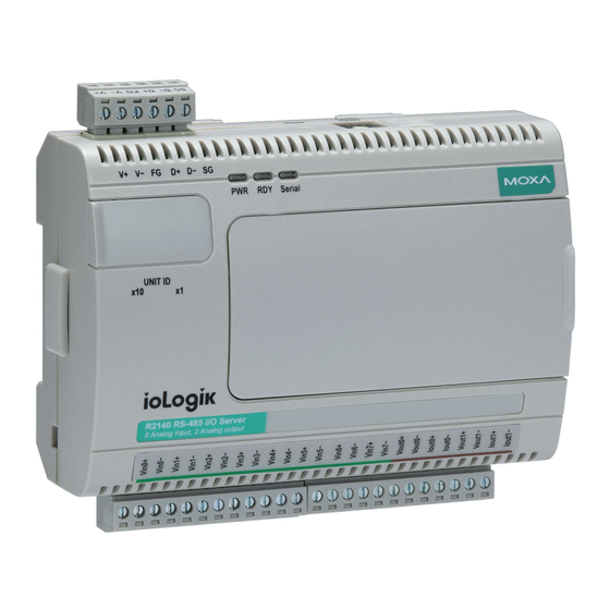
R2140 Introduction Product Overview TB1/TB2 NOTE The reset button restarts the server and resets all settings to factory defaults. Use a pointed object such as a straightened paper clip to hold the reset button down for 5 sec. The RDY LED will turn red as you are holding the reset button down. -
Page 11: Tb3 (Analog Input And Output Terminal)
R2140 Introduction TB3 (Analog Input and Output Terminal) Signal VIN0+ VIN0- VIN1+ VIN1- VIN2+ VIN2- VIN3+ VIN3- VIN4+ Signal VIN4- VIN5+ VIN5- VIN6+ VIN6- VIN7+ VIN7- VOUT0+ VOUT0- Signal IOUT IOUT VOUT1+ VOUT1- IOUT IOUT LED Indicators System LEDs... -
Page 12: Initial Setup
Initial Setup This chapter describes how to install the ioLogik R2140. The following topics are covered in this chapter: Hardware Installation Connecting the Power Grounding the ioLogik R2140 Connecting to Analog Sensors and Devices Setting the RS-485 Baudrate ... -
Page 13: Hardware Installation
Hardware Installation Connecting the Power Connect the 12 to 48 VDC power line to the ioLogik R2140’s terminal block (TB1). If power is properly supplied, the power LED will glow a solid red color until the system is ready ATTENTION Disconnect the power before installing and wiring. -
Page 14: Setting The Rs-485 Baudrate
The RS-485 port can run Modbus/RTU or I/O command sets. The baudrate is set by a physical dial on the back of the ioLogik R2140. The default settings are baudrate = 115200, parity check = N, data bits = 8, and stop bit = 1. -
Page 15: Software Installation
3. Search for the server: On the menu bar, select System Auto Scan Remote I/O Server. In the dialog window, select RS-232/485 I/O server and click Start Search. If ioAdmin is unable to find the ioLogik R2140, there may be a problem with your COM port settings. Click Port Settings to view or modify the settings. -
Page 16: Using Ioadmin
Using ioAdmin This chapter goes over the functions available in ioAdmin, the ioLogik R2140’s main configuration and management utility. The following topics are covered in this chapter: Introduction to ioAdmin Features of ioAdmin Searching for the Unit ... -
Page 17: Introduction To Ioadmin
Introduction to ioAdmin The ioLogik I/O server may be managed and configured over the Ethernet by ioAdmin, a Windows utility provided with your ioLogik R2140. ioAdmin’s graphical user interface gives you easy access to all status information and settings. ioAdmin consists of following software: •... -
Page 18: Searching For The Unit
R2140 Using ioAdmin Configuration File ioAdmin allows the entire configuration of the ioLogik R2140 to be saved as a file. The file is viewable as text and can serve three purposes: • as a record or backup of configuration •... - Page 19 2 for setting or viewing the baudrate. ATTENTION Even if ioAdmin is unable to find your ioLogik R2140, you may still access the On-line Wiring Guide. Please refer to the On-line Wiring Guide section for details. Once the ioLogik R2140 has been found by ioAdmin, you may monitor I/O status from the first tab of ioAdmin.
-
Page 20: Ioadmin Main Screen
This is ioAdmin’s main screen. The main window defaults to the I/O Configuration tab, which displays a graphic of the ioLogik R2140 and the status of every I/O channel below it. The other tabs in the main window take you to server and network settings, and further functions are available when you log on as an administrator. -
Page 21: Wiring Guide
R2140. You may access the wiring guide by right-clicking the graphic of the ioLogik R2140 in the I/O Configuration tab. Select Wiring Guide in the submenu to open a help file showing the wiring information and electrical characteristics of the ioLogik R2140. -
Page 22: Menu Items
R2140 Using ioAdmin Menu Items File From the File menu, you can export the list of I/O servers that are currently displayed in the navigation panel. You also can import a list of I/O servers into ioAdmin. When importing a server list, you will be prompted to select which servers on the list need to be imported. -
Page 23: Sort
R2140 Using ioAdmin Active Message Listen Port specifies the port number to use for Active Ethernet I/O messages. If your network uses a firewall, you can coordinate this setting with your firewall settings to ensure that active messages get through. -
Page 24: Main Window
R2140 Using ioAdmin Main Window I/O Configuration Tab (General) The I/O Configuration tab shows the status of every I/O channel. This is the default tab when you first open ioAdmin. Server Info Tab The Server Information tab provides the Modbus addresses for system configuration items. This helps you... -
Page 25: Server Settings Tab (General)
When making configuration changes, you will need to click Update or on Apply to save the changes. Some changes will require a restart of the ioLogik R2140 in order to take effect, and you will be given the option to restart the computer if necessary. -
Page 26: I/O Configuration Tab (Administrator)
+/-5V, +/-10V, 0-20 mA, and 4-20 mA. Configuring Analog Output Channels The ioLogik R2140 is equipped with 2 AO (analog output) channels that can be set individually to 0 to 10V, 4 to 20 mA. Power On Settings: Use this field to set the initial status for the AO channel when the ioLogik is powered on. -
Page 27: Server Settings Tab (Administrator)
Firmware Update Tab The ioLogik R2140 supports remote firmware updates through the Firmware Update tab. Enter the path to the firmware file or click on the icon to browse for the file. Click Update to update the firmware. The wizard will lead you through the process until the server is restarted. -
Page 28: Watchdog Tab
Update button. After the Watchdog is enabled, the ioLogik R2140 will enter safe status if the RS-485 connection is lost. Once the connection has been restored, you will need to return to the Watchdog Tab in order to exit safe status. -
Page 29: Server Context Menu
R2140 Using ioAdmin Server Context Menu The server context menu is accessed by right clicking on the server model name in the navigation panel. Connect Select this command to have ioAdmin attempt a re-connection over the network to the selected ioLogik server. - Page 30 R2140 Using ioAdmin Import System Config Select this command to reload a configuration that was exported to a text file. You will need to restart the ioLogik in order for the new configuration to take effect. This command may be used to restore a configuration after loading the factory defaults, or to duplicate a configuration to multiple ioLogik units.
-
Page 31: Cascading With Other I/O Servers
Cascading with Other I/O Servers The ioLogik R2140 can act both as a standalone I/O server and as an extension module to other I/O servers. This chapter explains how to use the ioLogik R2 140 as an extension module to ioLogik E2000 I/O servers. -
Page 32: Introductino
Cascading with Other I/O Servers Introductino The ioLogik R2140 can serve as an extension module to provide additional I/O channels to an ioLogik E2210 or E2240 Ethernet I/O server. Up to 31 units can be chained or cascaded together using each unit’s built-in connectors. -
Page 33: Using Ioadmin With Cascaded I/O Servers
R2140 Cascading with Other I/O Servers Using ioAdmin with Cascaded I/O Servers Adding One I/O Server ioAdmin can be used to access the I/O channels of all cascaded I/O servers. In the following instructions, the ioLogik E2210 and R2140 are used as examples: 1. -
Page 34: Adding Two Or More I/O Servers
R2140 Cascading with Other I/O Servers 4. The R2140 will appear with its unit ID under the E2210 in ioAdmin’s navigation panel. If the R2140 appears off-line, open its context menu in the navigation panel and select “Connect” to bring it on-line. Once the R2140 is on-line, you will be able to use ioAdmin to monitor and control its I/O channels. -
Page 35: Removing Cascaded I/O Servers
Delete I/O Server in the context menu. Limitations There are some limitations when using the ioLogik R2140 as an extension module to ioLogik E2000 servers. Although each I/O channel on a cascaded module can be monitored and controlled over Ethernet, the cascaded module will not support the following items: •... -
Page 36: Liquid Crystal Display Module (Lcm
The LCM is hot-pluggable and can be used to configure the network settings or display other settings. When plugged in, the module displays the ioLogik R2140 “home page,” and pressing any button takes you into the settings and configuration. - Page 37 R2140 Liquid Crystal Display Module (LCM) ATTENTION Any configuration changes that are made through the LCM will not take effect until the ioLogik R2140 is restarted.
-
Page 38: Modbus/Rtu Address Mappings
Modbus/RTU Address Mappings R2140 Modbus Mapping 0xxxx Read/Write Coils (Functions 1, 5, 15) Reference Address Data Type Description 00001 0x0000 1bit Reset CH0 AI min value Read: 0: no action Write: 1: reset AI min value 0: return illegal data value 00002 0x0001 1bit... - Page 39 R2140 Modbus/RTU Address Mappings Reference Address Data Type Description 00007 0x0006 1bit Reset CH6 AI min value Read: 0: no action Write: 1: reset AI min value 0: return illegal data value 00008 0x0007 1bit Reset CH7 AI min value...
-
Page 40: 3Xxxx Read Only Registers (Function 4
R2140 Modbus/RTU Address Mappings Reference Address Data Type Description 00015 0x000E 1bit Reset CH6 AI max value Read: 0: no action Write: 1: reset AI max value 0: return illegal data value 00016 0x000F 1bit Reset CH7 AI max value... -
Page 41: 4Xxxx Read/Write Registers (Functions 3, 6, 16
R2140 Modbus/RTU Address Mappings 4xxxx Read/Write Registers (Functions 3, 6, 16) Reference Address Data Type Description 40001 0x0000 1 word CH0 AO value (0 to 4095) 40002 0x0001 1 word CH1 AO value (0 to 4095) 40003 0x0002 1 word... - Page 42 R2140 Modbus/RTU Address Mappings Reference Address Data Type Description 40015 0x000E 1 word CH2 AI range 00: +/-150 mV 01: +/-500 mV 02: +/-5V 03: +/-10V 04: 0-20 mA 05: 4-20 mA Other: return illegal data value 40016 0x000F...
- Page 43 R2140 Modbus/RTU Address Mappings Reference Address Data Type Description 40021 0x0014 1 word CH0 AI power-on range 00: +/-150 mV 01: +/-500 mV 02: +/-5V 03: +/-10V 04: 0-20 mA 05: 4-20 mA Other: return illegal data value 40022...
- Page 44 R2140 Modbus/RTU Address Mappings Reference Address Data Type Description 40027 0x001A 1 word CH6 AI power-on range 00: +/-150 mV 01: +/-500 mV 02: +/-5V 03: +/-10V 04: 0-20 mA 05: 4-20 mA Other: return illegal data value 40028...
-
Page 45: Function 8
R2140 Modbus/RTU Address Mappings Reference Address Data Type Description 40033 0x0020 1 word CH4 AI safe range 00: +/-150 mV 01: +/-500 mV 02: +/-5V 03: +/-10V 04: 0-20 mA 05: 4-20 mA Other: return illegal data value 40034... -
Page 46: Factory Default Settings
Factory Default Settings The ioLogik R2140 is configured with the following factory defaults: RS-485 Unit ID Baudrate 115200 Kbps Communication Watchdog Disable AI Input Range -10 to 10V AO Output Range 0 to 10V AO Safe Status Off, 0V Power On Status... -
Page 47: Pinouts And Cable Wiring
Pinouts and Cable Wiring Pin Assignments System Bus Signal Signal Data+ SYNC Data- TB1 and TB2 (Power Input & RS-485 Connector) TB1 (Power Input) TB2 (RS-485) Signal NOTE: FG is Frame Ground, SG is Signal Ground... - Page 48 R2140 Pinouts and Cable Wiring TB3 (Analog Input and Output Terminal) Signal VIN0+ VIN0- VIN1+ VIN1- VIN2+ VIN2- VIN3+ VIN3- VIN4+ Signal VIN4- VIN5+ VIN5- VIN6+ VIN6- VIN7+ VIN7- VOUT0+ VOUT0- Signal IOUT IOUT VOUT1+ VOUT1- IOUT IOUT Analog Output...
- Page 49 R2140 Pinouts and Cable Wiring Analog Input Voltage Mode Schematic Current Mode Schematic Connection...
Need help?
Do you have a question about the ioLogik R2140 and is the answer not in the manual?
Questions and answers