Moxa Technologies NPort 5100A Series User Manual
Hide thumbs
Also See for NPort 5100A Series:
- Quick installation manual (6 pages) ,
- User manual (194 pages) ,
- Quick installation manual (2 pages)

Related Manuals for Moxa Technologies NPort 5100A Series


Summary of Contents for Moxa Technologies NPort 5100A Series
- Page 1 NPort 5100A Series Users Manual Fourth Edition, January 2013 www.moxa.com/product © 2013 Moxa Inc. All rights reserved.
-
Page 2: Copyright Notice
NPort 5100A Series Users Manual The software described in this manual is furnished under a license agreement and may be used only in accordance with the terms of that agreement. Copyright Notice © 2013 Moxa Inc. All rights reserved. Trademarks The MOXA logo is a registered trademark of Moxa Inc. -
Page 3: Table Of Contents
Table of Contents Introduction ............................1-1 Overview ............................1-2 Package Checklist ..........................1-2 Product Features ..........................1-2 Product Specifications ......................... 1-3 Getting Started ..........................2-1 Panel Layouts ............................. 2-2 NPort 5110A, NPort 5130A, NPort 5150A ..................2-2 NPort P5150A ..........................2-3 Connecting the Hardware ........................ - Page 4 Accessible IP Settings ........................5-31 Auto Warning Settings ........................5-32 Auto warning: Email and SNMP trap .................... 5-32 Mail Server ........................5-32 SNMP Trap Server ......................5-33 Event Type ..........................5-33 DCD changed ........................5-34 DSR changed ........................5-34 Upgrade Firmware ..........................5-34 Monitor ............................
- Page 5 Auto IP Report Protocol ........................D-1 Auto IP Report Format ........................D-1 Info [n] ............................D-1 ID List .............................. D-2 AP ID & Hardware ID Mapping Table ....................D-2 Compliance Notice ..........................E-1 Federal Communications Commission Statement ..................E-1...
-
Page 6: Introduction
Introduction The NPort 5100A and NPort 5100A-T are advanced, 1-port RS-232/422/485 serial device servers with low power consumption and full surge protection. The following topics are covered in this chapter: Overview Package Checklist Product Features Product Specifications... -
Page 7: Overview
Introduction Overview NPort 5100A series device servers, which include the NPort 5110A, 5130A, 5150A, and P5150A, are designed to make your industrial serial devices Internet ready instantly. The compact size of NPort 5100A device servers makes them the ideal choice for connecting your RS-232/422/485 serial devices, such as card readers and payment terminals, to an IP-based Ethernet LAN, making it possible for your software to access serial devices located anywhere on a local LAN, or the Internet. -
Page 8: Product Specifications
NPort 5100A Series Introduction Product Specifications Ethernet Interface Number of Ports: 1 Speed: 10/100 Mbps, auto MDI/MDIX Connector: 8-pin RJ45 Magnetic Isolation Protection: 1.5 KV built-in Serial Interface Number of Ports: 1 Serial Standards: NPort 5110A: RS-232 NPort 5130A: RS-422/485... - Page 9 NPort 5100A Series Introduction Power Requirements Input Voltage: 12 to 48 VDC Power Consumption: NPort 5110A: 82.5 mA @ 12 V, 47.3 mA @ 24 V NPort 5130A: 89.1 mA @ 12 V, 49.5 mA @ 24 V NPort 5150A: 92.4 mA @ 12 V, 52.8 mA @ 24 V...
-
Page 10: Getting Started
Getting Started This chapter includes information about installing the NPort 5100A. The following topics are covered in this chapter: Panel Layouts NPort 5110A, NPort 5130A, NPort 5150A NPort P5150A Connecting the Hardware Connecting the Power ... -
Page 11: Panel Layouts
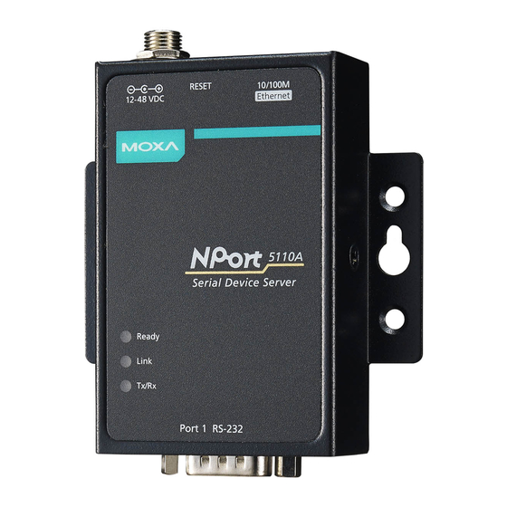
NPort 5100A Series Getting Started Panel Layouts NPort 5110A, NPort 5130A, NPort 5150A NOTE The layouts of the NPort 5130A and NPort 5150A are the same as the NPort 5110A. -
Page 12: Nport P5150A
NPort 5100A Series Getting Started NPort P5150A Connecting the Hardware This section describes how to connect the NPort 5100A to serial devices for first time testing purposes. Connecting the Power NPort P5150A Connect the NPort P5150A’s Ethernet port to a PoE switch. The P5150A will receive power from the switch. -
Page 13: Connecting To The Network
NPort 5100A Series Getting Started Connecting to the Network Connect one end of the Ethernet cable to the NPort 5100A’s 10/100M Ethernet port and the other end of the cable to the Ethernet network. The NPort 5100A will indicate a valid connection to the Ethernet in the following ways: •... -
Page 14: Nport 5130A/5150A Jumpers
NPort 5100A Series Getting Started NPort 5130A/5150A Jumpers To set a pull high/low resistor to 150 kΩ, make sure that the two jumpers (JP3 and JP4) assigned to the serial port are not shorted by jumper caps. This is the default setting. -
Page 15: Nport P5150A
NPort 5100A Series Getting Started NPort P5150A Pull-high Pull-low Terminator resistor resistor 1 kΩ 1 kΩ 120 Ω 150 kΩ* 150 kΩ* –* * Default ATTENTION Do not use the 1 kΩ setting on the NPort 5150A/P5150A when using the RS-232 interface. Doing so will... -
Page 16: Initial Ip Address Configuration
Initial IP Address Configuration When setting up your NPort 5100A for the first time, you should first configure the IP address. This chapter introduces the method to configure the device server’s IP address. For more details about network settings, see the Network Settings section from Chapter 5, Web Console Configuration. The following topics are covered in this chapter: ... -
Page 17: Initializing The Nport 5100A's Ip Address
NPort 5100A Series Initial IP Address Configuration Initializing the NPort 5100A’s IP Address 1. Determine whether your NPort 5100A needs to use a Static IP or Dynamic IP (either DHCP or BOOTP application). 2. If the NPort 5100A is used in a Static IP environment, you can use NPort Administration Suite, ARP, Web Console, Telnet Console, or Serial Console to configure the new IP address. -
Page 18: Arp
NPort 5100A Series Initial IP Address Configuration You can make use of the ARP (Address Resolution Protocol) command to set up an IP address for your NPort 5100A. The ARP command tells your computer to associate the NPort 5100A’s MAC address with the intended IP address. -
Page 19: Telnet Console
NPort 5100A Series Initial IP Address Configuration Telnet Console Depending on how your computer and network are configured, you may find it convenient to use network access to set up your NPort 5100A’s IP address. This can be done using Telnet. - Page 20 NPort 5100A Series Initial IP Address Configuration 6. Use the Backspace key to erase the current IP address, type in the new IP address, and then press Enter. 7. Press any key to continue. 8. Type m and then press Enter to return to the main menu.
-
Page 21: Serial Console (19200, N, 8, 1) (Nport 5110A/5150A/P5150A Only)
NPort 5100A Series Initial IP Address Configuration 9. Type s and then press Enter to Save/Restart the system. 10. Type y and then press Enter to save the new IP address and restart the NPort 5100A. Serial Console (19200, n, 8, 1) (NPort 5110A/5150A/P5150A only) You may use the RS-232 console port to set up the IP address for an NPort 5100A. - Page 22 NPort 5100A Series Initial IP Address Configuration 5. From the Property window’s Terminal page, select ANSI or VT100 for Terminal Type and then click OK. If you select Dumb Terminal as the terminal type, some of the console functions—especially the “Monitor”...
-
Page 23: Choosing The Proper Operation Mode
Choosing the Proper Operation Mode In this section, we describe the various NPort 5100A operation modes. The options include Real COM Mode, which uses a driver installed on the host computer, and operation modes that rely on TCP/IP socket programming concepts. After choosing the proper operation mode in this chapter, refer to Chapter 5 for detailed configuration parameter definitions. -
Page 24: Overview
NPort 5100A Series Choosing the Proper Operation Mode Overview NPort 5100A serial device servers network-enable traditional RS-232/422/485 devices. A serial device server is a tiny computer equipped with a CPU, real-time OS, and TCP/IP protocols that can bi-directionally translate data between the serial and Ethernet formats. Your computer can access, manage, and configure remote facilities and equipment over the Internet from anywhere in the world. -
Page 25: Rfc 2217 Mode
NPort 5100A Series Choosing the Proper Operation Mode ATTENTION Real COM Mode allows several hosts to have access control of the same NPort 5100A. The driver that comes with your NPort 5100A controls host access to attached serial devices by checking the host’s IP address. Refer to the Accessible IP Settings section of Chapter 5 for more details. -
Page 26: Udp Mode
NPort 5100A Series Choosing the Proper Operation Mode UDP Mode Compared to TCP communication, UDP is faster and more efficient. In UDP mode, you can unicast or multicast data from the serial device to one or multiple host computers, and the... -
Page 27: Reverse Telnet Mode
NPort 5100A Series Choosing the Proper Operation Mode Reverse Telnet Mode Console management is commonly used by connecting to Console/AUX or COM ports of routers, switches, and UPS units. Rtelnet works the same as TCP Server mode in that only one TCP port is listened to after booting up. -
Page 28: Web Console Configuration
Web Console Configuration The Web Console is the most user-friendly method available to configure the NPort 5100A. In this chapter, we introduce the Web Console function groups and function definitions. The following topics are covered in this chapter: Opening Your Browser ... -
Page 29: Opening Your Browser
NPort 5100A Series Web Console Configuration Opening Your Browser 1. Open your browser with the cookie function enabled. (To enable your browser for cookies, right click on your desktop Internet Explorer icon, select Properties, click on the Security tab, and then select the three Enable options as shown in the figure below.) - Page 30 NPort 5100A Series Web Console Configuration 4. The NPort 5100A homepage will open next. There are two buttons on this page: Quick setup and Export/Import. You can click Overview at any time to go back to this page. The following sections introduce these two convenient functions and all the other specific settings in the left Main Menu.
-
Page 31: Quick Setup
NPort 5100A Series Web Console Configuration Quick Setup Quick Setup streamlines configuration of your NPort into three basic and quick steps that cover the most commonly-used settings. At any time while in Quick Setup you may click the Back button to return to the previous step, or the Cancel button to reverse all settings. - Page 32 NPort 5100A Series Web Console Configuration Step 3/3: In this step, you can modify the serial settings. Review your settings on the Finish Settings page to confirm that they are correct, and then click the Save/Restart button to restart the device with the new settings.
-
Page 33: Export/Import
NPort 5100A Series Web Console Configuration Export/Import Export/Import allows you to back up and recover your settings. Click Export to store all configuration data into a default file, <Servername>.txt. Click the Import button to upload a configuration file to the NPort 5100A. -
Page 34: Network Settings
NPort 5100A Series Web Console Configuration Telnet console Setting Factory Default Necessity Enable or Disable Enable Required ATTENTION If you disable both the “Web console” and “Telnet console,” you can still use NPort Administrator to configure NPort 5100A device servers either locally or remotely over the network. Refer to Chapter 6 for more details. - Page 35 NPort 5100A Series Web Console Configuration IP configuration Method Function Definition Static User defined IP address, Netmask, Gateway DHCP DHCP Server assigned IP address, Netmask, Gateway, DNS, and Time Server DHCP/BOOTP DHCP Server assigned IP address, Netmask, Gateway, DNS, and Time Server, or BOOTP...
-
Page 36: Snmp Settings
NPort 5100A Series Web Console Configuration translates this kind of text-based domain name into the numeric IP address used to establish a TCP/IP connection. In order to use the NPort 5100A’s DNS feature, you need to configure the DNS server. Doing so allows the NPort 5100A to use a host’s domain name to access the host. -
Page 37: Serial Settings
NPort 5100A Series Web Console Configuration Auto report to IP Setting Factory Default Necessity E.g., 192.168.1.1 or URL (IP addresses of the None Optional form x.x.x.0 and x.x.x.255 are invalid.) Reports generated by the Auto report function will be automatically sent to this IP address. -
Page 38: Serial Parameters
NPort 5100A Series Web Console Configuration Port alias Setting Factory Default Necessity 1 to 15 characters None Optional (E.g., PLC-No.1) “Port alias” is included to allow easy identification of the serial devices that are connected to the NPort 5100A’s serial port. -
Page 39: Operating Settings
NPort 5100A Series Web Console Configuration Operating Settings Click Operating Settings, located under Main Menu, to display the operating settings for both of NPort 5100A’s serial ports. Real COM Mode TCP alive check time Setting Factory Default Necessity 0 to 99 min... - Page 40 NPort 5100A Series Web Console Configuration Max connection is usually used when the user needs to receive data from different hosts simultaneously. The factory default is 1. In this case, only one specific host can access this port of the NPort 5100A, and the Real COM driver on that host will have full control over the port.
- Page 41 NPort 5100A Series Web Console Configuration ATTENTION Delimiter 2 is optional. If left blank, then Delimiter 1 alone trips clearing of the buffer. If the size of the serial data received is greater than 1 KB, the NPort 5100A will automatically pack the data and send it to the Ethernet.
-
Page 42: Rfc 2217 Mode
NPort 5100A Series Web Console Configuration RFC 2217 Mode TCP alive check time Setting Factory Default Necessity 0 to 99 min 7 min Optional 0 min: TCP connection is not closed due to an idle TCP connection. 1 to 99 min: The NPort 5100A automatically closes the TCP connection if there is no TCP activity for the given time. -
Page 43: Tcp Server Mode
NPort 5100A Series Web Console Configuration [Delimiter + 1] or [Delimiter + 2]: The data will be transmitted when an additional byte (for Delimiter +1), or an additional 2 bytes (for Delimiter +2) of data is received after receiving the Delimiter. -
Page 44: Inactivity Time
NPort 5100A Series Web Console Configuration TCP alive check time Setting Factory Default Necessity 0 to 99 min 7 min Optional 0 min: TCP connection is not closed due to an idle TCP connection. 1 to 99 min: The NPort 5100A automatically closes the TCP connection if there is no TCP activity for the given time. - Page 45 NPort 5100A Series Web Console Configuration Allow driver control Setting Factory Default Necessity No or Yes Optional If “max connection” is greater than 1, the NPort will ignore driver control commands from all connected hosts. However, if you set “Allow driver control” to YES, control commands will be accepted. Note that since the NPort 5100A may get configuration changes from multiple hosts, the most recent command received will take precedence.
-
Page 46: Tcp Client Mode
NPort 5100A Series Web Console Configuration NPort 5100A transmits data stored in the buffer via TCP/IP, but only if the internal buffer is full or if the Force transmit time interval reaches the time specified under Force transmit timeout. The optimal Force transmit timeout depends on your application, but it must be at least larger than one character interval within the specified baudrate. - Page 47 NPort 5100A Series Web Console Configuration TCP alive check time Setting Factory Default Necessity 0 to 99 min 7 min Optional 0 min: TCP connection is not closed due to an idle TCP connection. 1 to 99 min: The NPort 5100A automatically closes the TCP connection if there is no TCP activity for the given time.
- Page 48 NPort 5100A Series Web Console Configuration Delimiter 2 Setting Factory Default Necessity 00 to FF (hex) None Optional Once the NPort 5100A receives both delimiters through its serial port, it immediately packs all data currently in its buffer and sends it to the NPort 5100A’s Ethernet port.
- Page 49 NPort 5100A Series Web Console Configuration Destination IP address 1/2/3/4 Setting Factory Default Necessity IP address or Domain None Required Name (E.g., 192.168.1.1) Allows the NPort 5100A to connect actively to the remote host whose IP address is set by this parameter.
-
Page 50: Udp Mode
NPort 5100A Series Web Console Configuration UDP Mode Packing length Setting Factory Default Necessity 0 to 1024 Optional Default = 0: The Delimiter Process will be followed, regardless of the length of the data packet. If the data length (in bytes) matches the configured value, the data will be forced out. The data length can be configured for 0 to 1024 bytes. - Page 51 NPort 5100A Series Web Console Configuration [Strip Delimiter]: When the Delimiter is received, the Delimiter is deleted (i.e., stripped), and the remaining data is transmitted. [Do nothing]: The data will be transmitted when the Delimiter is received. Force transmit Setting...
-
Page 52: Udp Multicast
NPort 5100A Series Web Console Configuration UDP Multicast A multicast is a packet sent by one host to multiple hosts. In multicast, each host that belongs to a specific multicast group will receive multicast packets for that group. To configure a host as a multicast receiver over the Internet, it must inform the routers on its LAN. -
Page 53: Pair Connection Slave Mode
NPort 5100A Series Web Console Configuration Pair Connection Slave Mode When you select Pair Connection Slave Mode for the Operation mode of one of the NPort 5100A device servers this NPort 5100A will be acting as a TCP server. TCP alive check time... -
Page 54: Dial-In
NPort 5100A Series Web Console Configuration Dial-in The NPort 5100A listens for a TCP/IP connection request from the remote Ethernet modem or host. The NPort 5100A’s response depends on the ATS0 value, as outlined below. ATS0=0 (default): The NPort 5100A will temporarily accept the TCP connection and then send the “RING” signal out through the serial port. -
Page 55: At Commands
NPort 5100A Series Web Console Configuration AT Commands The NPort 5100A supports the following common AT commands used with a typical modem: AT command Description Remarks Answer manually ATD <IP>:<Port> Dial up the IP address: Port No. ATE0=Echo OFF ATE1=Echo ON (default) -
Page 56: S Registers
NPort 5100A Series Web Console Configuration S Registers S Register Description & default value Remarks Ring to auto-answer (default=0) Ring counter (always=0) no action applied Escape code character (default=43 ASCII “+”) Return character (default=13 ASCII) Line feed character (default=10 ASCII) -
Page 57: Disabled Mode
NPort 5100A Series Web Console Configuration Inactivity time Setting Factory Default Necessity 0 to 65535 ms Optional Idle time setting for auto-disconnection. 0 min. means it will never disconnect. Local TCP port Setting Factory Default Necessity 1 to 65535 4001 Required Each of the NPort 5100A’s serial ports is mapped to a TCP port. -
Page 58: Accessible Ip Settings
NPort 5100A Series Web Console Configuration Accessible IP Settings The NPort 5100A uses an IP address based filtering method to control access to itself. Accessible IP Settings allows you to add or block remote host IP addresses to prevent unauthorized access. -
Page 59: Auto Warning Settings
NPort 5100A Series Web Console Configuration Auto Warning Settings Auto warning: Email and SNMP trap Mail Server Mail server Setting Factory Default Necessity IP Address or Domain None Optional Name User name Setting Factory Default Necessity 1 to 15 characters... -
Page 60: Snmp Trap Server
NPort 5100A Series Web Console Configuration SNMP Trap Server SNMP trap server IP or domain name Setting Factory Default Necessity IP address or Domain None Optional Name Event Type Cold start “Cold start” refers to starting the system from power off (contrast this with warm start). When performing a cold start, the NPort 5100A will automatically issue an Auto warning message by e-mail, or send an SNMP trap after booting up. -
Page 61: Dcd Changed
NPort 5100A Series Web Console Configuration DCD changed The DCD (Data Carrier Detect) signal has changed, also indicating that the modem connection status has changed. For example, a DCD change to high also means “Connected” between local modem and remote modem. -
Page 62: Monitor
NPort 5100A Series Web Console Configuration Monitor Monitor Line Click Line under Monitor to show the operation mode and status of each TCP/IP connection (IPx) for the serial port. Monitor Async Click Async under Monitor to show the current status of the serial port. -
Page 63: Monitor Async-Settings
NPort 5100A Series Web Console Configuration Monitor Async-Settings Click Async Setting under Monitor to show the run-time settings for the serial port. Change Password Input the “Old password” and “New password” to change the password. Leave the password boxes blank to erase the password. -
Page 64: Load Factory Default
NPort 5100A Series Web Console Configuration Load Factory Default This function will reset all of the NPort 5100A’s settings to the factory default values. Be aware that previous settings will be lost. 5-37... -
Page 65: Configuring Nport Administrator
Configuring NPort Administrator The following topics are covered in this chapter: Overview Installing NPort Administrator Configuration Broadcast Search Unlock Password Protection Configuring the NPort 5100A Upgrading the Firmware Export Configuration Import Configuration ... -
Page 66: Overview
Configuring NPort Administrator Overview Device Server Administrator lets you install and configure your NPort 5100A Series products easily over the network. Five function groups are provided to ease the installation process, allow off-line COM mapping, and provide monitoring and IP location server functions. - Page 67 NPort 5100A Series Configuring NPort Administrator 3. Click Next to install the program using the default program name, or select a different name. 4. Click Install to proceed with the installation. 5. The Installing window reports the progress of the installation.
- Page 68 NPort 5100A Series Configuring NPort Administrator 6. Click Next to proceed with the installation. 7. Click Finish to complete the installation of NPort Administration Suite.
-
Page 69: Configuration
NPort 5100A Series Configuring NPort Administrator Configuration The Administrator-Configuration window is divided into four parts. • The top section contains the function list and online help area. (Windows NT does not support this .chm file format.) • The five Administrator function groups are listed in the left section. -
Page 70: Unlock Password Protection
NPort 5100A Series Configuring NPort Administrator 2. The Broadcast Search window will open and display the Model, IP Address, MAC Address, and Progress of the search for that particular device. 3. When the search is complete, the Broadcast Search window will close, and the NPort 5100As that were located will be displayed in the right pane of the Administrator window. - Page 71 NPort 5100A Series Configuring NPort Administrator 2. After inputting the correct password, the Administrator will display an “Unlock ok” message. 3. The “Lock” status will change to “Unlock,” and the Administrator utility will keep this NPort 5100A in the Unlock status throughout this Administrator session.
-
Page 72: Configuring The Nport 5100A
NPort 5100A Series Configuring NPort Administrator Configuring the NPort 5100A In this section, we illustrate how to access the NPort 5100A’s configuration utility. You should first make sure that you can connect over the network from your computer to the NPort 5100A. -
Page 73: Upgrading The Firmware
NPort 5100A Series Configuring NPort Administrator ATTENTION You can simultaneously modify the configurations of multiple NPort 5100As that are of the same model. To select multiple NPort 5100As, hold down the Ctrl key when selecting additional NPort 5100As, or hold down the Shift key to select a group of NPort 5100As. -
Page 74: Export Configuration
NPort 5100A Series Configuring NPort Administrator Export Configuration To export the configuration of an NPort 5100A, right click the NPort 5100A, select Export Configuration, and then follow the onscreen instructions. The Export Configuration function is a handy tool that can be used to produce a text file containing the current configuration of a particular NPort 5100A. -
Page 75: Monitor
NPort 5100A Series Configuring NPort Administrator Monitor Initiating the Monitor Function To initiate the Monitor function, click Broadcast Search Monitor Add Target. 1. With Configuration selected under Function, use Broadcast Search to locate all NPorts on your LAN. - Page 76 NPort 5100A Series Configuring NPort Administrator 3. Select or de-select Monitor Items. Use the single arrowhead buttons to move highlighted items from one box to the other. Use the double arrowhead buttons to move all items in one box to the other.
- Page 77 NPort 5100A Series Configuring NPort Administrator 6. Right click in the NPort 5100A list section and select Go to start Monitoring the NPort 5100A. 7. For this example, the NPort 5100As shown in the list will be monitored. 8. When one of the NPort 5100As loses connection with the Monitor program, a warning alert will display automatically.
-
Page 78: Port Monitor
NPort 5100A Series Configuring NPort Administrator 10. If the NPort 5100A gets reconnected, a warning will be displayed to remind the user that the NPort 5100A is now “Alive.” 11. The NPort 5100As that were reconnected, and are now “Alive,” will be shown in black color. -
Page 79: Com Mapping
NPort 5100A Series Configuring NPort Administrator COM Mapping Windows Administration Suite comes with Windows Real COM drivers. After you install NPort Administration Suite, there are two ways to set up the NPort 5100A serial port as your host’s remote COM port. - Page 80 NPort 5100A Series Configuring NPort Administrator 4. The NPort 5100A list that appears is the list generated by the previous Broadcast Search. Select the NPort 5100A to which you would like to map COM ports. 5. Select COM Settings to modify COM No., default setting, etc.
- Page 81 NPort 5100A Series Configuring NPort Administrator milliseconds) than a native COM1, because it needs to work via Ethernet. That’s why the native COM ports on the motherboard can work fast with this function call, but the NPort requires much more time.
- Page 82 NPort 5100A Series Configuring NPort Administrator 9. After setting the COM Mapping, remember to select Apply Change to save the information in the host system registry. The host computer will not have the ability to use the COM port until after Apply Change is selected.
-
Page 83: Off-Line Com Mapping
NPort 5100A Series Configuring NPort Administrator Off-line COM Mapping 1. Add a target by inputting the IP address and selecting the Model Name without physically connecting the NPort 5100A to the network. 2. Modify the port settings as needed. 3. Right click in the NPort list section and select Apply Change. -
Page 84: Com Grouping
NPort 5100A Series Configuring NPort Administrator COM Grouping The “COM Grouping” function is designed to simulate the multi-drop behavior of serial communication over an Ethernet network. COM Grouping allows you to create a COM Group and redirect data from it to several physical COM ports on NPort device servers. - Page 85 NPort 5100A Series Configuring NPort Administrator 3. Select the Grouping selected port(s) together checkbox. 4. On the COM Grouping page, you can set “Read” and “Write” permissions for every serial port. It is necessary to set Signal Status in order to control the data transmission with specified control signals (e.g., DTR/RTS).
-
Page 86: Deleting A Com Group
NPort 5100A Series Configuring NPort Administrator 6. Finally, click Yes to confirm. Deleting a COM Group Follow the steps below to delete a COM Group and then auto-assign COM numbers for each port in the Group: 1. Select all serial ports in the Group you are deleting and then right-click to select COM Settings. -
Page 87: Adding A Port To A Com Group
NPort 5100A Series Configuring NPort Administrator 3. You will be able to view the serial ports that were assigned to and removed from the Group. Click Apply to apply the settings. 4. Finally, click Yes to confirm. Adding a Port to a COM Group Follow the steps below to add a serial port into an existing COM Group: 1. -
Page 88: Removing A Port From A Com Group
NPort 5100A Series Configuring NPort Administrator 3. You will be able to view the serial ports that were assigned to and removed from the Group. Click Apply to apply the settings. 4. Finally, click Yes to confirm. Removing a Port from a COM Group Follow the steps below to remove a serial port from a COM Group: 1. -
Page 89: Modify Ports In A Com Group
NPort 5100A Series Configuring NPort Administrator 3. You will be able to view the serial ports that were assigned to and removed from the Group. Click Apply to apply the settings. 4. Finally, click Yes to confirm. Modify Ports in a COM Group... - Page 90 NPort 5100A Series Configuring NPort Administrator 2. Select a COM number that is not in use or assigned to a Group. 3. Select the Grouping selected port(s) together checkbox and then click OK. 4. You will be able to view the serial ports that were assigned to and removed from the Group. Click Apply to apply the settings.
-
Page 91: Changing Advanced Settings And Serial Parameters Of The Com Group
NPort 5100A Series Configuring NPort Administrator Changing Advanced Settings and Serial Parameters of the COM Group 1. Check the port specified on the COM Grouping page as the signal port. 2. Select the ”Signal Status” controlled port and then right-click and select COM Settings. -
Page 92: Changing The Serial Port Specified As Signal Port For The Com Group
NPort 5100A Series Configuring NPort Administrator Changing the Serial Port Specified as Signal Port for the COM Group 1. Select a serial port in the Group and then right-click and select COM Settings. 2. Check the Grouping selected port(s) together check box. -
Page 93: Ip Address Report
When an NPort 5100A is used in a dynamic IP environment, users must spend more time with IP management tasks. NPort 5100A Series products periodically report their IP address to the IP location server, in case the dynamic IP has changed. - Page 94 NPort 5100A Series Configuring NPort Administrator 3. Configure the Local Listen Port to be the same as the NPort 5100A’s “Auto report to UDP port” setting. 4. Click Go to start receiving the Auto IP address report from the NPort 5100A.
-
Page 95: Ip Serial Lib
IP Serial LIB The following topics are covered in this chapter: Overview What is IP Serial Library? Why Use IP Serial Library? How to Install IP Serial Library IP Serial LIB Function Groups Sample Program... -
Page 96: Overview
NPort 5100A Series IP Serial LIB Overview What is IP Serial Library? IP Serial Library is a Windows library with frequently used serial command sets and subroutines. IP Serial Library is designed to reduce the complexity and poor efficiency of serial communication over TCP/IP. For example, Telnet can only transfer data, but it can’t monitor or configure the serial line’s parameters. -
Page 97: Ip Serial Lib Function Groups
NPort 5100A Series IP Serial LIB IP Serial LIB Function Groups Server Control Port Control Input/Output Data Port Status Inquiry Miscellaneous nsio_init nsio_open nsio_read nsio_lstatus nsio_break nsio_end nsio_close nsio_SetReadTimeouts nsio_data_status nsio_break_on nsio_resetserver nsio_ioctl nsio_write nsio_break_off nsio_checkalive nsio_flowctrl nsio_SetWriteTimeouts nsio_breakcount nsio_DTR... -
Page 98: Pinouts And Cable Wiring
Pinouts and Cable Wiring The following topics are covered in this appendix: Port Pinout Diagrams Ethernet Port Pinouts NPort 5110A Serial Port Pinouts NPort 5130A Serial Port Pinouts NPort 5150A/P5150A Serial Port Pinouts Cable Wiring Diagrams ... -
Page 99: Port Pinout Diagrams
NPort 5100A Series Pinouts and Cable Wiring Port Pinout Diagrams Ethernet Port Pinouts Signal NPort 5110A Serial Port Pinouts DB9 Male RS-232 Port Pinouts for NPort 5110A RS-232 NPort 5130A Serial Port Pinouts DB9 Male RS-422/485 Port Pinouts for the NPort 5130A... -
Page 100: Nport 5150A/P5150A Serial Port Pinouts
NPort 5100A Series Pinouts and Cable Wiring NPort 5150A/P5150A Serial Port Pinouts DB9 Male RS-232/422/485 Port Pinouts for the NPort 5150A RS-232 RS-422 / 4-wire RS-485 2-wire RS-485 TxD-(A) – TxD+(B) – RxD+(B) Data+(B) RxD-(A) Data-(A) – – – –... -
Page 101: Well Known Port Numbers
Well Known Port Numbers In this appendix, which is included for your reference, we provide a list of Well Known port numbers that may cause network problems if you set the NPort 5100A to one of these ports. Refer to RFC 1700 for Well Known port numbers, or refer to the following introduction from the IANA. - Page 102 NPort 5100A Series Well Known Port Numbers UDP Socket Application Service Reserved Management Utility Echo Discard Active Users (systat) Daytime Any private printer server Resource Location Protocol Host name server (names server) Whois (nickname) (Login Host Protocol) (Login) Domain Name Server (domain)
-
Page 103: Snmp Agents With Mib Ii & Rs232/422/485 Link Groups
SNMP Agents with MIB II & RS232/422/485 Link Groups The NPort 5100A has a built-in SNMP (Simple Network Management Protocol) software agent that supports SNMP Trap, RFC1317 RS-232/422/485 like groups, and RFC 1213 MIB-II. The following table lists the standard MIB-II groups, as well as the variables implemented for the NPort 5100A. -
Page 104: Rfc1317: Rs-232/422/485 Mib Objects
NPort 5100A Series SNMP Agents with MIB II & RS232/422/485 Link Groups UDP MIB TCP MIB SNMP MIB UdpInDatagrams tcpRtoAlgorithm snmpInPkts UdpNoPorts tcpRtoMin snmpOutPkts UdpInErrors tcpRtoMax snmpInBadVersions UdpOutDatagrams tcpMaxConn snmpInBadCommunityNames UdpLocalAddress tcpActiveOpens snmpInASNParseErrs UdpLocalPort tcpPassiveOpens snmpInTooBigs tcpAttempFails snmpInNoSuchNames Address Translation MIB... -
Page 105: Auto Ip Report Protocol
Auto IP Report Protocol The NPort Series provides several ways to configure Ethernet IP addresses. One of them is DHCP Client. When you set up the NPort to use DHCP Client to configure Ethernet IP addresses, it will automatically send a DHCP request over the Ethernet to find the DHCP Server. -
Page 106: Id List
NPort 5100A Series Auto IP Report Protocol ID List ID Value Description Length Note Server Name Variable ASCII char Hardware ID Little-endian MAC Address 6 bytes MAC address. If the MAC address is "00-90-E8-01-02-03", the MAC[0] is 0, MAC[1] is 0x90(hex), MAC[2] is 0xE8(hex), and so on. -
Page 107: Compliance Notice
Compliance Notice CE Warning This is a Class A product. In a domestic environment, this product may cause radio interference, in which case the user may be required to take appropriate measures. Federal Communications Commission Statement This device complies with part 15 of the FCC Rules. Operation is subject to the following two conditions: (1) This device may not cause harmful interference, and (2) this device must accept any interference received, including interference that may cause undesired operation.
Need help?
Do you have a question about the NPort 5100A Series and is the answer not in the manual?
Questions and answers