Table of Contents
Advertisement
Quick Links
Advertisement
Table of Contents

Subscribe to Our Youtube Channel
Related Manuals for Blatchford S400


Summary of Contents for Blatchford S400
- Page 1 S400 Instructions for Use ENS400 Instructions for Use...
-
Page 2: Description And Purpose
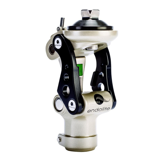
1 Description and purpose These instructions are for use by the practitioner. • The ENS400 knee is to be used exclusively as part of a lowerlimb prosthesis. Intended User: • Recommended for amputees with Mobility Grades 2/3 • Weight limit for a user is up to 125kg/275lbs Contra-indications •... - Page 3 2 Construction Principle Parts: • Frame Aluminum Alloy, Brass, Stainless Steel, Steel • Knee head Aluminum Alloy, Stainless Steel • Knee control Various materials principally Aluminum Alloy, Stainless Steel, Polyurethane Bumper Fig. 1 (a) Posterior View (b) Anterior View (c) Lateral View of Knee Unit...
- Page 4 Spare parts of ENS400 (spare parts available with the spare parts number shown)
-
Page 5: Safety Information
3 Function • Adjustable extension assist spring • Upper pyramids facilitating alignment adjustment for all socket designs • Adjustable the head level of knee • A low profile carbon body for variety of residual limb lengths • The Flex/Ext resistance of knee adjustable 4 Safety Information The caution symbol highlights safety information which must be followed carefully Be aware of finger trap hazard at all times... -
Page 6: Maintenance
5 Maintenance Maintenance must be carried out by qualified personnel. A visual inspection annually is recommended. Check for visual defects that may affect proper function. A loaner system is available should servicing be required. The wearer should be advised: Any changes in performance of this device must be reported to the Clinician/Practitioner. -
Page 7: Limitation On Use
Intended Life: • Service life of the product is covered by the warranty period. • This product is recommended for use with other Blatchford Products. • A local risk assessment should be carried out based upon activity and usage Lifting Loads: Amputee weight and activity is governed by the stated limits. -
Page 8: Alignment And Set-Up
7 Alignment and Set-up Users be aware of potential finger trap hazard... - Page 9 1. Assemble the prosthesis. 2. Recommended static/bench alignment is with the foot externally rotated 5 degrees, the socket flexed 5 degrees and abducted 5 degrees. However this will solely be dependent upon the alignment of the residuum. 3. Make sure that foot is perpendicular to the pylon on the ground level. 4.
- Page 10 8 Knee Adjustment 8.1 Extension assist adjustment of the base spring unit Use 6mm wrench driver and turn the screw of base spring unit clockwise to compress the inner spring to increase extension assistance. Turn the screw anti-clockwise to decrease the extension assistance.
- Page 11 In general, making head tilting backwards is the most common adjustment. On the other hand, too much knee head leaning forward will lower the function of rubber bumper between head and back linkage. 8.4 The upper male adaptor adjustment Loose the bolt of head male pyramid by a 8mm wrench driver.
- Page 12 9 Maintenance of knee unit 9.1 Change the front head axial cover: Use a small screw driver to pick out the “C” spring so that the front axial cover can be taken off for replacement. 9.2 Change rubber bumpers Use a small screw driver to pick out the rubber bumper of knee level adjusting screw which is located on upper linkage bar and replace it with a new one.
- Page 13 9.4 Change the spring of knee base Use this special tool to take out whole base set of knee. Carefully remove the spring from base. Replace new spring or other components of this base. Clean all components of base if necessary. Assemble the whole base unit back to knee by following reversed steps.
-
Page 14: Technical Specification
10 Technical Specification -10˚C to 50˚C 14˚F to122˚F Operating and Storage Temperature Range: Weight: 678g Recommended Activity: K2/K3 Maximum User Weight: K2: 125kg (275lbs) K3: 100kg (220lbs) Proximal Alignment attachment: Rotatable Socket Attachment Plate Rotatable Lotus Adaptor Distal Alignment attachment: Tube Clamp Tube clamp torque setting: 12Nm... -
Page 15: Warranty
11 Warranty Warranted for 2 years from the date of invoice by Blatchford Products Ltd. The user should be aware that changes or modifications not expressly approved will void the warranty. 12 Liability The manufacturer recommends using the device only under the specified conditions and for the intended purposes. - Page 16 Tel: +47 (0) 55 91 88 60 Fax: +33 (0) 467 073 630 Email: post@ortopro.no Tel: +1 (0) 800 548 3534 Email: contact@blatchford.fr www.ortopro.no Fax: +1 (0) 800 929 3636 www.blatchford.fr Email: info@blatchfordus.com www.blatchfordus.com © Blatchford Products Limited 2019. All rights reserved. v1.0_2019...
Need help?
Do you have a question about the S400 and is the answer not in the manual?
Questions and answers