Table of Contents
Advertisement
Quick Links
User Guide
3659 0.8 mm Calibration/Verification
Kit and 2300-580-R System
Performance Verification Software
VectorStar™ ME7838D Modular Broadband/Millimeter-Wave VNA System
with 3739C BB Test Set and MA25300A mm-Wave Modules
VectorStar™ ME7838D4 Modular Broadband/Millimeter-Wave VNA System
with 3739C BB Test Set and MA25300A mm-Wave Modules
VectorStar™ ME7838G Modular Broadband/Millimeter-Wave VNA System
with MA25400A mm-Wave Modules (Verification to 145 GHz)
Anritsu Company
Part Number: 10410-00327
490 Jarvis Drive
Revision: D
Morgan Hill, CA 95037-2809
Published: January 2020
USA
Copyright 2020 Anritsu Company, USA. All Rights Reserved.
http://www.anritsu.com
Advertisement
Table of Contents
Troubleshooting

Related Manuals for Anritsu 3659


Summary of Contents for Anritsu 3659
- Page 1 VectorStar™ ME7838G Modular Broadband/Millimeter-Wave VNA System with MA25400A mm-Wave Modules (Verification to 145 GHz) Anritsu Company Part Number: 10410-00327 490 Jarvis Drive Revision: D Morgan Hill, CA 95037-2809 Published: January 2020 Copyright 2020 Anritsu Company, USA. All Rights Reserved. http://www.anritsu.com...
-
Page 3: Table Of Contents
Model 3659 0.8 mm Calibration/Verification Kit ........ - Page 4 Procedure ............. 3-19 Contents-2 PN: 10410-00327 Rev. D 3659 0.8 mm Cal/Ver Kit & 2300-580-R PVS UG...
- Page 5 Procedure ............. 3-42 Contents-3 PN: 10410-00327 Rev. D 3659 0.8 mm Cal/Ver Kit & 2300-580-R PVS UG...
- Page 6 Procedure ............. 4-22 Contents-4 PN: 10410-00327 Rev. D 3659 0.8 mm Cal/Ver Kit & 2300-580-R PVS UG...
- Page 7 Procedure ............. . 6-5 Contents-5 PN: 10410-00327 Rev. D 3659 0.8 mm Cal/Ver Kit & 2300-580-R PVS UG...
- Page 8 Connector Types and Cross-Mating Compatibility ......6-10 Contents-6 PN: 10410-00327 Rev. D 3659 0.8 mm Cal/Ver Kit & 2300-580-R PVS UG...
-
Page 9: Chapter 1 - 3659 0.8 Mm Calibration/Verification Kit Overview
Chapter 6, “Maintenance”. Operation and use of the 3659 0.8 mm Calibration/Verification Kit is documented in procedures in the VectorStar Operation Manual and Measurement Guide. The components in this kit are of the highest quality and accuracy. All components are NIST Note (National Institute of Standards Technology) traceable. -
Page 10: Verification Software Overview
• National Instruments Model PCI-GPIB (Driver Software Version 1.2 and above) Regardless of which GPIB hardware and software is used, the GPIB card must be configured as “GPIB0.” You also need a GPIB cable to interface the PC to the broadband measurement system (Anritsu PN: 2100-2). Printer A printer is not required for operation because the verification results and data are stored in four files on the computer hard disk drive. -
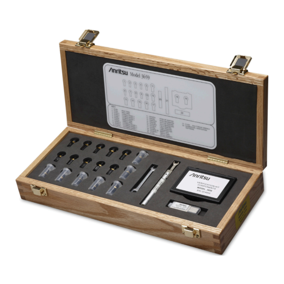
Page 11: Model 3659 0.8 Mm Calibration/Verification Kit
3659 0.8 mm Calibration/Verification Kit Overview 1-4 Model 3659 0.8 mm Calibration/Verification Kit Model 3659 0.8 mm Calibration/Verification Kit The 3659 0.8 mm Calibration/Verification Kit is shown in Figure 1-1 below with the listed components. 0.8 VERIFICATION KIT COMPONENTS MODEL 3659... -
Page 12: Related Documentation
0.8 mm Component Verification Data for VectorStar ME7838D/D4/G Broadband/Millimeter Wave VNA Systems • Documentation Figure 1-1. 3659 0.8 mm Calibration/Verification Kit Components (2 of 2) Related Documentation For more information on VNA systems, calibration/verification kits, and other supporting accessories, refer to the Anritsu web site: http://www.anritsu.com. -
Page 13: Chapter 2 - Using The 2300-580-R Software With Vectorstar Me7838D
VectorStar ME7838D Introduction This chapter describes the use of the Anritsu 2300-580-R Performance Verification Software (PVS) with the VectorStar ME7838D Modular BB/mm-Wave VNA Measurement System. The ME7838D is based on the VectorStar MS4647A/B Vector Network Analyzer running VectorStar for the MS4647B model Application Version 2.1.0 or higher and equipped with Option 08x or the MS4647A model Application Version 1.7.6 and... -
Page 14: Mm Verification Application Installation
2-1) should then appear. Figure 2-1. PVS Installation and Documentation Screen 6. On the navigation page, click the Install Anritsu 0.8 mm Verification Application Software link. 7. The first of several installation dialog boxes appears. PN: 10410-00327 Rev. D 3659 0.8 mm Cal/Ver Kit & 2300-580-R PVS UG... - Page 15 8. Two installation wizard setup dialog boxes appear in sequence. Click Next to proceed through each dialog box. The final dialog box shows an installation progress bar. Figure 2-2. Installation Confirmation and Progress Dialog Boxes – Click Next on each 3659 0.8 mm Cal/Ver Kit & 2300-580-R PVS UG PN: 10410-00327 Rev. D...
- Page 16 11. If desired, open the User Guide (this document) and save and/or print a copy. 12. The PVS application is available from either the Start or Program menu of the PC Controller. PN: 10410-00327 Rev. D 3659 0.8 mm Cal/Ver Kit & 2300-580-R PVS UG...
-
Page 17: Running The Verification Software
Windows. 2. Locate the Anritsu 0.8 mm Verification icon (shown below) on the desktop and double-click it. 3. The program displays an About dialog box with version information. Click OK to continue. - Page 18 10. The Select Broadband System Model dialog box appears. Select the ME7838D system and click Ok. Figure 2-7. Select Model Dialog PN: 10410-00327 Rev. D 3659 0.8 mm Cal/Ver Kit & 2300-580-R PVS UG...
-
Page 19: Enter Port 1 Bb/Mm-Wave Module Information
Enter the Port 1 BB/mm-Wave Module model number and click OK. Figure 2-8. Anritsu 0.8 mm Verification Dialog – Port 1 BB/mm-Wave Module – Model Number 11. Enter the Port 1 BB/mm-Wave Module serial number and click OK. Figure 2-9. -
Page 20: Enter Port 2 Bb/Mm-Wave Module Information
Enter Port 2 BB/mm-Wave Module Information 12. Enter the Port 2 BB/mm-Wave Module model number and click OK. Figure 2-10. Anritsu 0.8 mm Verification Dialog – Port 2 BB/mm-Wave Module – Model Number 13. Enter the Port 2 BB/mm-Wave Module serial number and click OK. -
Page 21: Enter Test Set Information
14. Enter the Test Set model number and click OK. 3739C Figure 2-12. Anritsu 0.8 mm Verification Dialog – Test Set – Model Number 15. Enter the Test Set serial number found on the rear panel and click OK. Figure 2-13. Anritsu 0.8 mm Verification Dialog – Test Set – Serial Number 16. -
Page 22: Application Interface - Setup Menu Tab
The following procedure continues the program setup from the previous section: 1. In the Calibration Kit Type area, select 0.8 mm Coax. 2. In the Serial Number (5 Digits) area, enter the serial number for the 3659 Calibration/Verification Kit. At least five (5) digits are required. - Page 23 Using the 2300-580-R Software with VectorStar ME7838D 2-6 Application Interface – Setup Menu Tab 5. Follow the dialog box instructions for installing the 3659 calibration coefficients into the VNA, then click Figure 2-15. Install Calibration Kit Coefficients Dialog 6. The VNA displays an acknowledgment dialog box when the file load is complete, indicating that 10 files were loaded.
- Page 24 Band” on page 2-35. After selecting the frequency range, click OK. The Verification Kit Information area appears. Figure 2-17. ME7838D Application Interface – Setup Menu Tab 2-12 PN: 10410-00327 Rev. D 3659 0.8 mm Cal/Ver Kit & 2300-580-R PVS UG...
- Page 25 Calibration Kit). When the Serial Number is complete, the Locate USB Drive Kit Data on PC area appears. Figure 2-18. ME7838D Application Interface – Setup Menu Tab 3659 0.8 mm Cal/Ver Kit & 2300-580-R PVS UG PN: 10410-00327 Rev. D 2-13...
- Page 26 E, F, or G drive assignments. Navigate to the verification kit data in the file-path location shown in the example below (for this example, the USB drive was at E:\): E:\0.8mm_Component_Verification_Data\0.8mm_3659_xxxxxx (where xxxxxx is the serial number of the Kit) 2-14 PN: 10410-00327 Rev. D 3659 0.8 mm Cal/Ver Kit & 2300-580-R PVS UG...
- Page 27 USB drive. Once the data is found, the Verification Kit Data Path information appears in the text field. Click Next > to return to the Application Interface dialog box. Figure 2-20. USB Drive Locater Dialog 3659 0.8 mm Cal/Ver Kit & 2300-580-R PVS UG PN: 10410-00327 Rev. D 2-15...
- Page 28 11. Click Verify Files on USB Drive. The application checks the files on the USB drive to verify that all files are present and that each has the proper number of data points. Figure 2-21. ME7838D Application Interface – Setup Menu Tab 2-16 PN: 10410-00327 Rev. D 3659 0.8 mm Cal/Ver Kit & 2300-580-R PVS UG...
- Page 29 14. The program execution continues in either Section 2-7, “Low-Band Calibration” on page 2-18 Section 2-8, “High-Band Calibration” on page 2-21 depending on the previous band selection. 3659 0.8 mm Cal/Ver Kit & 2300-580-R PVS UG PN: 10410-00327 Rev. D 2-17...
-
Page 30: Low-Band Calibration
Connect the Female Cal Kit Isolation Device to VNA Port 2. c. When ready to proceed, click OK. Figure 2-24. VNA Calibration: Step 1 of 5 Dialog 2-18 PN: 10410-00327 Rev. D 3659 0.8 mm Cal/Ver Kit & 2300-580-R PVS UG... - Page 31 Connect the Female Short #1 (1.20 mm) to VNA Port 2. c. When ready to proceed, click OK. Figure 2-26. VNA Calibration: Step 3 of 5 Dialog 3659 0.8 mm Cal/Ver Kit & 2300-580-R PVS UG PN: 10410-00327 Rev. D 2-19...
- Page 32 Figure 2-28. VNA Calibration: Step 5 of 5 Dialog 7. The program execution skips to Section 2-9 “Application Interface – Main Menu Tab” on page 2-24. 2-20 PN: 10410-00327 Rev. D 3659 0.8 mm Cal/Ver Kit & 2300-580-R PVS UG...
-
Page 33: High-Band Calibration
Connect the Female Cal Kit Isolation Device to VNA Port 2. c. When ready to proceed, click OK. Figure 2-30. VNA Calibration: Step 1 of 5 Dialog 3659 0.8 mm Cal/Ver Kit & 2300-580-R PVS UG PN: 10410-00327 Rev. D 2-21... - Page 34 When ready to proceed, click OK. Figure 2-33. VNA Calibration: Step 4 of 5 Dialog 6. The VNA Calibration: Step 5 of 5 dialog box appears. 2-22 PN: 10410-00327 Rev. D 3659 0.8 mm Cal/Ver Kit & 2300-580-R PVS UG...
- Page 35 Figure 2-34. VNA Calibration: Step 5 of 5 Dialog 7. The program execution continues to Section 2-9 “Application Interface – Main Menu Tab” on page 2-24. 3659 0.8 mm Cal/Ver Kit & 2300-580-R PVS UG PN: 10410-00327 Rev. D 2-23...
-
Page 36: Application Interface - Main Menu Tab
Figure 2-35. ME7838D Application Interface – Main Menu Tab 2-24 PN: 10410-00327 Rev. D 3659 0.8 mm Cal/Ver Kit & 2300-580-R PVS UG... -
Page 37: Auto Scale Display Button
Auto Scale Display Button This command automatically scales each channel on the Anritsu Vector Network Analyzer. It is the same as using the VectorStar VNA menus to navigate to and select either the Auto Scale Active Channel or Auto Scale All Channels buttons. -
Page 38: Default Display Scale Button
Choose The Restart Method dialog box provides selectable options for a full restart, a restart with another verification kit, or a restart with another calibration kit. Figure 2-37. Choose The Restart Method Dialog 2-26 PN: 10410-00327 Rev. D 3659 0.8 mm Cal/Ver Kit & 2300-580-R PVS UG... -
Page 39: Quit Button
Main Menu tab shown above in Table 2-35 on page 2-24 above. Mismatched Thru SN This field is used to enter the serial number of the matched thru. 3659 0.8 mm Cal/Ver Kit & 2300-580-R PVS UG PN: 10410-00327 Rev. D 2-27... -
Page 40: 2-10 Application Interface - Serial Number Tab Functions
• Operator Name • Calibration Kit • Test Set • Verification Kit • Vector Network Analyzer • mm-Wave Modules Figure 2-38. ME7838D Application Interface – Serial Number Tab 2-28 PN: 10410-00327 Rev. D 3659 0.8 mm Cal/Ver Kit & 2300-580-R PVS UG... -
Page 41: Matched Thru Tests
4. When ready to proceed, click OK. The Connect Mismatched Thru Male Connector dialog box appears. Figure 2-40. Connect the Mismatched Thru Dialog 5. Connect the Matched Thru male connector to VNA Port 1 with the label facing up. 3659 0.8 mm Cal/Ver Kit & 2300-580-R PVS UG PN: 10410-00327 Rev. D 2-29... - Page 42 After it completes, the Matched Thru Test - Sweep 2 dialog box appears. Figure 2-41. Matched Thru Test, Sweep 1 and Sweep 2 Dialog Boxes 2-30 PN: 10410-00327 Rev. D 3659 0.8 mm Cal/Ver Kit & 2300-580-R PVS UG...
-
Page 43: 2-12 Mismatched Thru Tests
If the Run All Tests button on the Application Interface - Main Menu tab was selected, the Matched Thru tests (described above in Section 2-11 “Matched Thru Tests” on page 2-29 is executed first, followed by the Mismatched Thru tests described in this section. 3659 0.8 mm Cal/Ver Kit & 2300-580-R PVS UG PN: 10410-00327 Rev. D 2-31... -
Page 44: Procedure
• The Mismatched Thru verification standard is the device with two scribe lines. The verification standards must be connected to the 0.8 mm Coupler Ports and not to the VNA Note ports. 2-32 PN: 10410-00327 Rev. D 3659 0.8 mm Cal/Ver Kit & 2300-580-R PVS UG... - Page 45 6. When ready to continue, click OK. The Mismatched Thru Test - Sweep 1 dialog box is displayed first followed by the Mismatched Thru Test - Sweep 2 dialog box. Figure 2-45. Status Dialogs 3659 0.8 mm Cal/Ver Kit & 2300-580-R PVS UG PN: 10410-00327 Rev. D 2-33...
- Page 46 Please note this is for reference only and that the actual data on the VNA display may not be identical. Figure 2-46. MS4640A/B Series VNA, Typical Mismatched Thru Data in Low Band 2-34 PN: 10410-00327 Rev. D 3659 0.8 mm Cal/Ver Kit & 2300-580-R PVS UG...
-
Page 47: 2-13 Saving Verification Data
Step 7 on page 2-6. 4. On the Setup Menu, repeat the data entry for the following items. Click OK when ready to proceed to the next step. 3659 0.8 mm Cal/Ver Kit & 2300-580-R PVS UG PN: 10410-00327 Rev. D 2-35... -
Page 48: 2-15 Troubleshooting
2. Check to see that the Windows GPIB is present on the boot drive, that it is properly configured, and that it passes the National Instruments hardware and software tests. If, after checking the above, you are still having difficulty, contact your Anritsu customer service center and ask for the Vector Network Analyzer support engineer for further assistance. - Page 49 5. Assure all active systems have been powered on at least one hour before the start of the calibrations. If you still have difficulty after following the above steps, please contact Anritsu customer service and ask for the Vector Network Analyzer support engineer for further assistance.
- Page 50 2-15 Troubleshooting Using the 2300-580-R Software with VectorStar ME7838D 2-38 PN: 10410-00327 Rev. D 3659 0.8 mm Cal/Ver Kit & 2300-580-R PVS UG...
-
Page 51: Chapter 3 - Using The 2300-580-R Software With Vectorstar Me7838D4
VectorStar ME7838D4 Introduction This chapter describes the use of the Anritsu 2300-580-R Performance Verification Software (PVS) with the VectorStar ME7838D4 Modular BB/mm-Wave VNA Measurement System. The ME7838D4 is based on the VectorStar MS4647A/B Vector Network Analyzer running VectorStar for the MS4647B model Application Version 2.1.0 or higher and equipped with Option 08x or the MS4647A model Application Version 1.7.6 and... -
Page 52: Mm Verification Application Installation
3-1) should then appear. Figure 3-1. PVS Installation and Documentation Screen 6. On the navigation page, click the Install Anritsu 0.8 mm Verification Application Software link. 7. The first of several installation dialog boxes appears. PN: 10410-00327 Rev. D 3659 0.8 mm Cal/Ver Kit & 2300-580-R PVS UG... - Page 53 8. Two installation wizard setup dialog boxes appear in sequence. Click Next to proceed through each dialog box. The final dialog box shows an installation progress bar. Figure 3-2. Installation Confirmation and Progress Dialog Boxes – Click Next on each 3659 0.8 mm Cal/Ver Kit & 2300-580-R PVS UG PN: 10410-00327 Rev. D...
- Page 54 11. If desired, open the User Guide (this document) and save and/or print a copy. 12. The PVS application is available from either the Start or Program menu of the PC Controller. PN: 10410-00327 Rev. D 3659 0.8 mm Cal/Ver Kit & 2300-580-R PVS UG...
-
Page 55: Running The Verification Software
Windows. 2. Locate the Anritsu 0.8 mm Verification icon (shown below) on the desktop and double-click it. 3. The program displays an About dialog box with version information. Click OK to continue. - Page 56 Port 4. If testing Port 3 and Port 4 is requested, select Yes. If testing port 1 and 2 is requested, select Figure 3-7. Found Instrument Dialog PN: 10410-00327 Rev. D 3659 0.8 mm Cal/Ver Kit & 2300-580-R PVS UG...
-
Page 57: Enter Port 1 Bb/Mm-Wave Module Information
1. Enter the Port 1 BB/mm-Wave Module model number and click OK. Figure 3-8. Anritsu 0.8 mm Verification Dialog – Port 1 BB/mm-Wave Module – Model Number 2. Enter the Port 1 BB/mm-Wave Module serial number and click OK. Figure 3-9. -
Page 58: Enter Port 2 Bb/Mm-Wave Module Information
Enter Port 2 BB/mm-Wave Module Information 3. Enter the Port 2 BB/mm-Wave Module model number and click OK. Figure 3-10. Anritsu 0.8 mm Verification Dialog – Port 2 BB/mm-Wave Module – Model Number 4. Enter the Port 2 BB/mm-Wave Module serial number and click OK. -
Page 59: Enter Port 3 Bb/Mm-Wave Module Information
3-11. 1. Enter the Port 3 BB/mm-Wave Module model number and click OK. Figure 3-12. Anritsu 0.8 mm Verification Dialog – Port 3 BB/mm-Wave Module – Model Number 2. Enter the Port 3 BB/mm-Wave Module serial number and click OK. -
Page 60: Enter Port 4 Bb/Mm-Wave Module Information
Enter Port 4 BB/mm-Wave Module Information 3. Enter the Port 4 BB/mm-Wave Module model number and click OK. Figure 3-14. Anritsu 0.8 mm Verification Dialog – Port 4 BB/mm-Wave Module – Model Number 4. Enter the Port 4 BB/mm-Wave Module serial number and click OK. -
Page 61: Enter Test Set Information For All Ports
1. Enter the Test Set model number for Ports 1 and 2 and click OK. 3739C Figure 3-16. Anritsu 0.8 mm Verification Dialog – Test Set – Model Number 2. Enter the Test Set serial number for Ports 1 and 2 found on the rear panel and click OK. - Page 62 4. Enter the Test Set serial number for Ports 3 and 4 found on the rear panel and click OK. Figure 3-19. Anritsu 0.8 mm Verification Dialog – Test Set – Serial Number 5. The program execution continues as shown in Section 3-6, “Application Interface –...
-
Page 63: Application Interface - Setup Menu Tab
The following procedure continues the program setup from the previous section: 1. In the Calibration Kit Type area, select 0.8 mm Coax. 2. In the Serial Number (5 Digits) area, enter the serial number for the 3659 Calibration/Verification Kit. At least five (5) digits are required. - Page 64 Using the 2300-580-R Software with VectorStar ME7838D4 4. The Install Calibration-Kit Coefficients to the VNA dialog box appears. 5. Follow the dialog box instructions for installing the 3659 calibration coefficients into the VNA, then click Figure 3-21. Install Calibration Kit Coefficients Dialog 6.
- Page 65 Band” on page 3-36. After selecting the frequency range, click OK. The Verification Kit Information area appears. Figure 3-23. ME7838D4 Application Interface – Setup Menu Tab 3659 0.8 mm Cal/Ver Kit & 2300-580-R PVS UG PN: 10410-00327 Rev. D 3-15...
- Page 66 Figure 3-24. ME7838D4 Application Interface – Setup Menu Tab 9. In the Locate USB Drive Kit Data on PC area, click the Go To USB Drive Locator button. 3-16 PN: 10410-00327 Rev. D 3659 0.8 mm Cal/Ver Kit & 2300-580-R PVS UG...
- Page 67 USB drive. Once the data is found, the Verification Kit Data Path information appears in the text field. Click Next > to return to the Application Interface dialog box. Figure 3-25. USB Drive Locator Dialog 3659 0.8 mm Cal/Ver Kit & 2300-580-R PVS UG PN: 10410-00327 Rev. D 3-17...
- Page 68 Section 3-16, “Low-Band Calibration – Port 3/Port 4” on page 3-39 Section 3-17, “High-Band Calibration – Port 3/Port 4” on page 3-42, depending on the previous band selection. 3-18 PN: 10410-00327 Rev. D 3659 0.8 mm Cal/Ver Kit & 2300-580-R PVS UG...
-
Page 69: Low-Band Calibration - Port 1/Port 2
Connect the Female Cal Kit Isolation Device to VNA Port 2. c. When ready to proceed, click OK. Figure 3-28. VNA Calibration: Step 1 of 5 Dialog 3659 0.8 mm Cal/Ver Kit & 2300-580-R PVS UG PN: 10410-00327 Rev. D 3-19... - Page 70 Connect the Female Short #1 (1.20 mm) to VNA Port 2. c. When ready to proceed, click OK. Figure 3-30. VNA Calibration: Step 3 of 5 Dialog 3-20 PN: 10410-00327 Rev. D 3659 0.8 mm Cal/Ver Kit & 2300-580-R PVS UG...
- Page 71 Figure 3-32. VNA Calibration: Step 5 of 5 Dialog 7. The program execution continues with Section 3-9 “Application Interface – Main Menu Tab” on page 3-25. 3659 0.8 mm Cal/Ver Kit & 2300-580-R PVS UG PN: 10410-00327 Rev. D 3-21...
-
Page 72: High-Band Calibration - Port 1/Port 2
Connect the Female Cal Kit Isolation Device to VNA Port 2. c. When ready to proceed, click OK. Figure 3-34. VNA Calibration: Step 1 of 5 Dialog 3-22 PN: 10410-00327 Rev. D 3659 0.8 mm Cal/Ver Kit & 2300-580-R PVS UG... - Page 73 When ready to proceed, click OK. Figure 3-37. VNA Calibration: Step 4 of 5 Dialog 6. The VNA Calibration: Step 5 of 5 dialog box appears. 3659 0.8 mm Cal/Ver Kit & 2300-580-R PVS UG PN: 10410-00327 Rev. D 3-23...
- Page 74 Figure 3-38. VNA Calibration: Step 5 of 5 Dialog 7. The program execution continues to Section 3-9 “Application Interface – Main Menu Tab” on page 3-25. 3-24 PN: 10410-00327 Rev. D 3659 0.8 mm Cal/Ver Kit & 2300-580-R PVS UG...
-
Page 75: Application Interface - Main Menu Tab
Figure 3-39. ME7838D4 Application Interface – Main Menu Tab 3659 0.8 mm Cal/Ver Kit & 2300-580-R PVS UG PN: 10410-00327 Rev. D 3-25... -
Page 76: Auto Scale Display Button
Auto Scale Display Button This command automatically scales each channel on the Anritsu Vector Network Analyzer. It is the same as using the VectorStar VNA menus to navigate to and select either the Auto Scale Active Channel or Auto Scale All Channels buttons. -
Page 77: Default Display Scale Button
Choose The Restart Method dialog box provides selectable options for a full restart, a restart with another verification kit, or a restart with another calibration kit. Figure 3-41. Choose The Restart Method Dialog 3659 0.8 mm Cal/Ver Kit & 2300-580-R PVS UG PN: 10410-00327 Rev. D 3-27... -
Page 78: Quit Button
Main Menu tab shown in Figure 3-39 on page 3-25. Mismatched Thru SN This field is used to enter the serial number of the matched thru. 3-28 PN: 10410-00327 Rev. D 3659 0.8 mm Cal/Ver Kit & 2300-580-R PVS UG... -
Page 79: 3-10 Application Interface - Serial Number Tab Functions
• Operator Name • Calibration Kit • Test Set • Verification Kit • Vector Network Analyzer • mm-Wave Modules Figure 3-42. ME7838D4 Application Interface – Serial Number Tab 3659 0.8 mm Cal/Ver Kit & 2300-580-R PVS UG PN: 10410-00327 Rev. D 3-29... -
Page 80: Matched Thru Tests - Port 1/Port 2
4. When ready to proceed, click OK. The Connect Mismatched Thru Male Connector dialog box appears. Figure 3-44. Connect the Mismatched Thru Dialog 5. Connect the Matched Thru male connector to VNA Port 1 with the label facing up. 3-30 PN: 10410-00327 Rev. D 3659 0.8 mm Cal/Ver Kit & 2300-580-R PVS UG... - Page 81 After it completes, the Matched Thru Test - Sweep 2 dialog box appears. Figure 3-45. Matched Thru Test, Sweep 1 and Sweep 2 Dialog Boxes 3659 0.8 mm Cal/Ver Kit & 2300-580-R PVS UG PN: 10410-00327 Rev. D...
- Page 82 Main Menu Tab” on page 3-25. 10. If the Run All Tests button was selected, the program execution continues with Section 3-12, “Mismatched Thru Tests – Port 1/Port 2”. 3-32 PN: 10410-00327 Rev. D 3659 0.8 mm Cal/Ver Kit & 2300-580-R PVS UG...
-
Page 83: Mismatched Thru Tests - Port 1/Port 2
• The Mismatched Thru verification standard is the device with two scribe lines. The verification standards must be connected to the 0.8 mm Coupler Ports and not to the VNA Note ports. 3659 0.8 mm Cal/Ver Kit & 2300-580-R PVS UG PN: 10410-00327 Rev. D 3-33... - Page 84 6. When ready to continue, click OK. The Mismatched Thru Test - Sweep 1 dialog box is displayed first followed by the Mismatched Thru Test - Sweep 2 dialog box. Figure 3-49. Status Dialogs 3-34 PN: 10410-00327 Rev. D 3659 0.8 mm Cal/Ver Kit & 2300-580-R PVS UG...
- Page 85 VNA display may not be identical. Figure 3-50. MS4640A/B Series VNA, Typical Mismatched Thru Data in Low Band 3659 0.8 mm Cal/Ver Kit & 2300-580-R PVS UG PN: 10410-00327 Rev. D...
-
Page 86: 3-13 Saving Verification Data
Section 3-5, “Running the Verification Software”, Step 7 on page 3-6. 3-36 PN: 10410-00327 Rev. D 3659 0.8 mm Cal/Ver Kit & 2300-580-R PVS UG... -
Page 87: 3-15 Troubleshooting
2. Check to see that the Windows GPIB is present on the boot drive, that it is properly configured, and that it passes the National Instruments hardware and software tests. If, after checking the above steps, you are still having difficulty, contact your Anritsu customer service center and ask for the Vector Network Analyzer support engineer for further assistance. - Page 88 5. Assure all active systems have been powered on at least one hour before the start of the calibrations. If you still have difficulty after following the above steps, please contact Anritsu customer service and ask for the Vector Network Analyzer support engineer for further assistance.
-
Page 89: Low-Band Calibration - Port 3/Port 4
Connect the Female Cal Kit Isolation Device to VNA Port 4. c. When ready to proceed, click OK. Figure 3-54. VNA Calibration: Step 1 of 5 Dialog 3659 0.8 mm Cal/Ver Kit & 2300-580-R PVS UG PN: 10410-00327 Rev. D 3-39... - Page 90 Connect the Female Short #1 (1.20 mm) to VNA Port 4. c. When ready to proceed, click OK. Figure 3-56. VNA Calibration: Step 3 of 5 Dialog 3-40 PN: 10410-00327 Rev. D 3659 0.8 mm Cal/Ver Kit & 2300-580-R PVS UG...
- Page 91 Figure 3-58. VNA Calibration: Step 5 of 5 Dialog 7. The program execution returns to Section 3-9 “Application Interface – Main Menu Tab” on page 3-25. 3659 0.8 mm Cal/Ver Kit & 2300-580-R PVS UG PN: 10410-00327 Rev. D 3-41...
-
Page 92: High-Band Calibration - Port 3/Port 4
Connect the Female Cal Kit Isolation Device to VNA Port 4. c. When ready to proceed, click OK. Figure 3-60. VNA Calibration: Step 1 of 5 Dialog 3-42 PN: 10410-00327 Rev. D 3659 0.8 mm Cal/Ver Kit & 2300-580-R PVS UG... - Page 93 5. The VNA Calibration: Step 4 of 5 dialog box appears. a. Connect the Male 2.06 mm Short #3 to VNA Port 3. b. Connect the Female 1.20 mm Short #1 to VNA Port 4. 3659 0.8 mm Cal/Ver Kit & 2300-580-R PVS UG PN: 10410-00327 Rev. D 3-43...
- Page 94 Figure 3-64. VNA Calibration: Step 5 of 5 Dialog 7. The program execution continues to Section 3-18 “Application Interface – Main Menu Tab” on page 3-45. 3-44 PN: 10410-00327 Rev. D 3659 0.8 mm Cal/Ver Kit & 2300-580-R PVS UG...
-
Page 95: 3-18 Application Interface - Main Menu Tab
Figure 3-65. ME7838D4 Application Interface – Main Menu Tab 3659 0.8 mm Cal/Ver Kit & 2300-580-R PVS UG PN: 10410-00327 Rev. D 3-45... -
Page 96: Auto Scale Display Button
Auto Scale Display Button This command automatically scales each channel on the Anritsu Vector Network Analyzer. It is the same as using the VectorStar VNA menus to navigate to and select either the Auto Scale Active Channel or Auto Scale All Channels buttons. -
Page 97: Default Display Scale Button
Choose The Restart Method dialog box provides selectable options for a full restart, a restart with another verification kit, or a restart with another calibration kit. Figure 3-67. Choose The Restart Method Dialog 3659 0.8 mm Cal/Ver Kit & 2300-580-R PVS UG PN: 10410-00327 Rev. D 3-47... -
Page 98: Quit Button
Main Menu tab shown in Figure 3-39 on page 3-25. Mismatched Thru SN This field is used to enter the serial number of the matched thru. 3-48 PN: 10410-00327 Rev. D 3659 0.8 mm Cal/Ver Kit & 2300-580-R PVS UG... -
Page 99: 3-19 Application Interface - Serial Number Tab Functions
• Operator Name • Calibration Kit • Test Set • Verification Kit • Vector Network Analyzer • mm-Wave Modules Figure 3-68. ME7838D4 Application Interface – Serial Number Tab 3659 0.8 mm Cal/Ver Kit & 2300-580-R PVS UG PN: 10410-00327 Rev. D 3-49... -
Page 100: Matched Thru Tests - Port 3/Port 4
The verification standards must be connected to the 0.8 mm Coupler Ports and not to the VNA Note ports. 3. Enter the serial number of the Matched Thru. 3-50 PN: 10410-00327 Rev. D 3659 0.8 mm Cal/Ver Kit & 2300-580-R PVS UG... - Page 101 After it completes, the Matched Thru Test - Sweep 2 dialog box appears. Figure 3-71. Matched Thru Test, Sweep 1 and Sweep 2 Dialog Boxes 3659 0.8 mm Cal/Ver Kit & 2300-580-R PVS UG PN: 10410-00327 Rev. D...
- Page 102 3-45. The dialog box is shown in Figure 3-65. 10. If the Run All Tests button was selected, the program execution continues with Section 3-21, “Mismatched Thru Tests – Port 3/Port 4”. 3-52 PN: 10410-00327 Rev. D 3659 0.8 mm Cal/Ver Kit & 2300-580-R PVS UG...
-
Page 103: Mismatched Thru Tests - Port 3/Port 4
• The Mismatched Thru verification standard is the device with two scribe lines. The verification standards must be connected to the 0.8 mm Coupler Ports and not to the VNA Note ports. 3659 0.8 mm Cal/Ver Kit & 2300-580-R PVS UG PN: 10410-00327 Rev. D 3-53... - Page 104 6. When ready to continue, click OK. The Mismatched Thru Test - Sweep 1 dialog box is displayed first followed by the Mismatched Thru Test - Sweep 2 dialog box. Figure 3-75. Status Dialogs 3-54 PN: 10410-00327 Rev. D 3659 0.8 mm Cal/Ver Kit & 2300-580-R PVS UG...
- Page 105 VNA display may not be identical. Figure 3-76. MS4640A/B Series VNA, Typical Mismatched Thru Data in Low Band 3659 0.8 mm Cal/Ver Kit & 2300-580-R PVS UG PN: 10410-00327 Rev. D...
-
Page 106: 3-22 Saving Verification Data
Section 3-5, “Running the Verification Software”, Step 7 on page 3-6. 3-56 PN: 10410-00327 Rev. D 3659 0.8 mm Cal/Ver Kit & 2300-580-R PVS UG... -
Page 107: 3-24 Troubleshooting
2. Check to see that the Windows GPIB is present on the boot drive, that it is properly configured, and that it passes the National Instruments hardware and software tests. If, after checking the above steps, you are still having difficulty, contact your Anritsu customer service center and ask for the Vector Network Analyzer support engineer for further assistance. - Page 108 5. Assure all active systems have been powered on at least one hour before the start of the calibrations. If you still have difficulty after following the above steps, please contact Anritsu customer service and ask for the Vector Network Analyzer support engineer for further assistance.
-
Page 109: Chapter 4 - Using The 2300-580-R Software With Vectorstar Me7838G
Required Equipment Required VectorStar ME7838G Broadband System, 70 kHz to 220 GHz Instruments and Components (Verification will be done to 145 GHz with the 3659 kit and the 2300-580-R software). The VectorStar ME7838G Broadband/Millimeter Wave Measurement System consists of: • VectorStar MS4647B VNA, 70 kHz to 70 GHz, V Connectors, equipped with Option 08x •... -
Page 110: Mm Verification Application Installation
4-1) should then appear. Figure 4-1. PVS Installation and Documentation Screen 6. On the navigation page, click the Install Anritsu 0.8 mm Verification Application Software link. 7. The first of several installation dialog boxes appears. PN: 10410-00327 Rev. D 3659 0.8 mm Cal/Ver Kit & 2300-580-R PVS UG... - Page 111 8. Two installation wizard setup dialog boxes appear in sequence. Click Next to proceed through each dialog box. The final dialog box shows an installation progress bar. Figure 4-2. Installation Confirmation and Progress Dialog Boxes – Click Next on each 3659 0.8 mm Cal/Ver Kit & 2300-580-R PVS UG PN: 10410-00327 Rev. D...
- Page 112 11. If desired, open the User Guide (this document) and save and/or print a copy. 12. The PVS application is available from either the Start or Program menu of the PC Controller. PN: 10410-00327 Rev. D 3659 0.8 mm Cal/Ver Kit & 2300-580-R PVS UG...
-
Page 113: Running The Verification Software
Windows. 2. Locate the Anritsu 0.8 mm Verification icon (shown below) on the desktop and double-click it. 3. The program displays an About dialog box with version information. Click OK to continue. - Page 114 10. The Select Broadband System Model dialog box appears. Select the ME7838G system and click Ok. Figure 4-7. Select Model Dialog PN: 10410-00327 Rev. D 3659 0.8 mm Cal/Ver Kit & 2300-580-R PVS UG...
-
Page 115: Enter Port 1 Bb/Mm-Wave Module Information
Enter the Port 1 BB/mm-Wave Module model number and click OK. Figure 4-8. Anritsu 0.8 mm Verification Dialog – Port 1 BB/mm-Wave Module – Model Number 11. Enter the Port 1 BB/mm-Wave Module serial number and click OK. Figure 4-9. -
Page 116: Enter Port 2 Bb/Mm-Wave Module Information
Enter Port 2 BB/mm-Wave Module Information 12. Enter the Port 2 BB/mm-Wave Module model number and click OK. Figure 4-10. Anritsu 0.8 mm Verification Dialog – Port 2 BB/mm-Wave Module – Model Number 13. Enter the Port 2 BB/mm-Wave Module serial number and click OK. -
Page 117: Enter Test Set Information
14. Enter the Test Set model number and click OK. 3739C Figure 4-12. Anritsu 0.8 mm Verification Dialog – Test Set – Model Number 15. Enter the Test Set serial number found on the rear panel and click OK. Figure 4-13. Anritsu 0.8 mm Verification Dialog – Test Set – Serial Number 16. -
Page 118: Application Interface - Setup Menu Tab
The following procedure continues the program setup from the previous section: 1. In the Calibration Kit Type area, select 0.8 mm Coax. 2. In the Serial Number (5 Digits) area, enter the serial number for the 3659 Calibration/Verification Kit. At least five (5) digits are required. - Page 119 Using the 2300-580-R Software with VectorStar ME7838G 4-6 Application Interface – Setup Menu Tab 5. Follow the dialog box instructions for installing the 3659 calibration coefficients into the VNA, then click Figure 4-15. Install Calibration Kit Coefficients Dialog 6. The VNA displays an acknowledgment dialog box when the file load is complete, indicating that 10 files were loaded.
- Page 120 Band” on page 4-36. After selecting the frequency range, click OK. The Verification Kit Information area appears. Figure 4-17. ME7838G Application Interface – Setup Menu Tab 4-12 PN: 10410-00327 Rev. D 3659 0.8 mm Cal/Ver Kit & 2300-580-R PVS UG...
- Page 121 Calibration Kit). When the Serial Number is complete, the Locate USB Drive Kit Data on PC area appears. Figure 4-18. ME7838G Application Interface – Setup Menu Tab 3659 0.8 mm Cal/Ver Kit & 2300-580-R PVS UG PN: 10410-00327 Rev. D 4-13...
- Page 122 E, F, or G drive assignments. Navigate to the verification kit data in the file-path location shown in the example below (for this example, the USB drive was at E:\): E:\0.8mm_Component_Verification_Data\0.8mm_3659_xxxxxx (where xxxxxx is the serial number of the Kit) 4-14 PN: 10410-00327 Rev. D 3659 0.8 mm Cal/Ver Kit & 2300-580-R PVS UG...
- Page 123 USB drive. Once the data is found, the Verification Kit Data Path information appears in the text field. Click Next > to return to the Application Interface dialog box. Figure 4-20. USB Drive Locater Dialog 3659 0.8 mm Cal/Ver Kit & 2300-580-R PVS UG PN: 10410-00327 Rev. D 4-15...
- Page 124 11. Click Verify Files on USB Drive. The application checks the files on the USB drive to verify that all files are present and that each has the proper number of data points. Figure 4-21. ME7838G Application Interface – Setup Menu Tab 4-16 PN: 10410-00327 Rev. D 3659 0.8 mm Cal/Ver Kit & 2300-580-R PVS UG...
- Page 125 14. The program execution continues in either Section 4-7, “Low-Band Calibration” on page 4-18 Section 4-8, “High-Band Calibration” on page 4-22 depending on the previous band selection. 3659 0.8 mm Cal/Ver Kit & 2300-580-R PVS UG PN: 10410-00327 Rev. D 4-17...
-
Page 126: Low-Band Calibration
1. The 0.8 mm Verification Install Adapter dialog box appears. a. Install the 33.8G50 adapters on MMW-Modules Port 1 and Port 2. Figure 4-23. Anritsu 0.8 mm Verification Dialog 4-18 PN: 10410-00327 Rev. D 3659 0.8 mm Cal/Ver Kit & 2300-580-R PVS UG... - Page 127 Connect the Female Cal Kit Isolation Device to VNA Port 2. c. When ready to proceed, click OK. Figure 4-25. VNA Calibration: Step 1 of 5 Dialog 3659 0.8 mm Cal/Ver Kit & 2300-580-R PVS UG PN: 10410-00327 Rev. D 4-19...
- Page 128 Connect the Female Short #1 (1.20 mm) to VNA Port 2. c. When ready to proceed, click OK. Figure 4-27. VNA Calibration: Step 3 of 5 Dialog 4-20 PN: 10410-00327 Rev. D 3659 0.8 mm Cal/Ver Kit & 2300-580-R PVS UG...
- Page 129 Figure 4-29. VNA Calibration: Step 5 of 5 Dialog 7. The program execution skips to Section 4-9 “Application Interface – Main Menu Tab” on page 4-25. 3659 0.8 mm Cal/Ver Kit & 2300-580-R PVS UG PN: 10410-00327 Rev. D 4-21...
-
Page 130: High-Band Calibration
Connect the Female Cal Kit Isolation Device to VNA Port 2. c. When ready to proceed, click OK. Figure 4-31. VNA Calibration: Step 1 of 5 Dialog 4-22 PN: 10410-00327 Rev. D 3659 0.8 mm Cal/Ver Kit & 2300-580-R PVS UG... - Page 131 When ready to proceed, click OK. Figure 4-34. VNA Calibration: Step 4 of 5 Dialog 6. The VNA Calibration: Step 5 of 5 dialog box appears. 3659 0.8 mm Cal/Ver Kit & 2300-580-R PVS UG PN: 10410-00327 Rev. D 4-23...
- Page 132 Figure 4-35. VNA Calibration: Step 5 of 5 Dialog 7. The program execution continues to Section 4-9 “Application Interface – Main Menu Tab” on page 4-25. 4-24 PN: 10410-00327 Rev. D 3659 0.8 mm Cal/Ver Kit & 2300-580-R PVS UG...
-
Page 133: Application Interface - Main Menu Tab
Figure 4-36. ME7838G Application Interface – Main Menu Tab 3659 0.8 mm Cal/Ver Kit & 2300-580-R PVS UG PN: 10410-00327 Rev. D 4-25... -
Page 134: Auto Scale Display Button
Auto Scale Display Button This command automatically scales each channel on the Anritsu Vector Network Analyzer. It is the same as using the VectorStar VNA menus to navigate to and select either the Auto Scale Active Channel or Auto Scale All Channels buttons. -
Page 135: Default Display Scale Button
Choose The Restart Method dialog box provides selectable options for a full restart, a restart with another verification kit, or a restart with another calibration kit. Figure 4-38. Choose The Restart Method Dialog 3659 0.8 mm Cal/Ver Kit & 2300-580-R PVS UG PN: 10410-00327 Rev. D 4-27... -
Page 136: Quit Button
Main Menu tab shown above in Table 4-36 on page 4-25 above. Mismatched Thru SN This field is used to enter the serial number of the matched thru. 4-28 PN: 10410-00327 Rev. D 3659 0.8 mm Cal/Ver Kit & 2300-580-R PVS UG... -
Page 137: 4-10 Application Interface - Serial Number Tab Functions
• Operator Name • Calibration Kit • Test Set • Verification Kit • Vector Network Analyzer • mm-Wave Modules Figure 4-39. ME7838G Application Interface – Serial Number Tab 3659 0.8 mm Cal/Ver Kit & 2300-580-R PVS UG PN: 10410-00327 Rev. D 4-29... -
Page 138: Matched Thru Tests
4. When ready to proceed, click OK. The Connect Mismatched Thru Male Connector dialog box appears. Figure 4-41. Connect the Mismatched Thru Dialog 5. Connect the Matched Thru male connector to VNA Port 1 with the label facing up. 4-30 PN: 10410-00327 Rev. D 3659 0.8 mm Cal/Ver Kit & 2300-580-R PVS UG... - Page 139 After it completes, the Matched Thru Test - Sweep 2 dialog box appears. Figure 4-42. Matched Thru Test, Sweep 1 and Sweep 2 Dialog Boxes 3659 0.8 mm Cal/Ver Kit & 2300-580-R PVS UG PN: 10410-00327 Rev. D...
-
Page 140: 4-12 Mismatched Thru Tests
If the Run All Tests button on the Application Interface - Main Menu tab was selected, the Matched Thru tests (described above in Section 4-11 “Matched Thru Tests” on page 4-30 is executed first, followed by the Mismatched Thru tests described in this section. 4-32 PN: 10410-00327 Rev. D 3659 0.8 mm Cal/Ver Kit & 2300-580-R PVS UG... -
Page 141: Procedure
• The Mismatched Thru verification standard is the device with two scribe lines. The verification standards must be connected to the 0.8 mm Coupler Ports and not to the VNA Note ports. 3659 0.8 mm Cal/Ver Kit & 2300-580-R PVS UG PN: 10410-00327 Rev. D 4-33... - Page 142 6. When ready to continue, click OK. The Mismatched Thru Test - Sweep 1 dialog box is displayed first followed by the Mismatched Thru Test - Sweep 2 dialog box. Figure 4-46. Status Dialogs 4-34 PN: 10410-00327 Rev. D 3659 0.8 mm Cal/Ver Kit & 2300-580-R PVS UG...
- Page 143 Please note this is for reference only and that the actual data on the VNA display may not be identical. Figure 4-47. MS4640A/B Series VNA, Typical Mismatched Thru Data in Low Band 3659 0.8 mm Cal/Ver Kit & 2300-580-R PVS UG PN: 10410-00327 Rev. D...
-
Page 144: 4-13 Saving Verification Data
Step 7 on page 4-6. 4. On the Setup Menu, repeat the data entry for the following items. Click OK when ready to proceed to the next step. 4-36 PN: 10410-00327 Rev. D 3659 0.8 mm Cal/Ver Kit & 2300-580-R PVS UG... -
Page 145: 4-15 Troubleshooting
2. Check to see that the Windows GPIB is present on the boot drive, that it is properly configured, and that it passes the National Instruments hardware and software tests. If, after checking the above, you are still having difficulty, contact your Anritsu customer service center and ask for the Vector Network Analyzer support engineer for further assistance. - Page 146 5. Assure all active systems have been powered on at least one hour before the start of the calibrations. If you still have difficulty after following the above steps, please contact Anritsu customer service and ask for the Vector Network Analyzer support engineer for further assistance.
-
Page 147: Chapter 5 - Gpib Card And Instrument Settings
Your board type such as PCIIA or PCI Base I/O Address Consult the GPIB card manual DMA Channel Consult the GPIB card manual Interrupt Level Consult the GPIB card manual 3659 0.8 mm Cal/Ver Kit & 2300-580-R PVS UG PN: 10410-00327 Rev. D... -
Page 148: Instrument Settings
Type of compare on EOS 8-bit EOS Byte 0Ah or decimal 10 Send EOI at End of Write YES or checked Enable Repeat Addressing NO or unchecked PN: 10410-00327 Rev. D 3659 0.8 mm Cal/Ver Kit & 2300-580-R PVS UG... -
Page 149: Chapter 6 - Maintenance
This appendix provides instructions for the maintenance and proper connection and torquing of the RF connectors on your Anritsu instrument, and components you connect to the instrument, including the calibration kit components described in this manual. Following the recommendations in this document prevents shortened connector life and less equipment downtime due to connector-related failures. -
Page 150: Visual Inspection
Note Regular cleaning and proper connection techniques will minimize wear on the plating due to abrasion from debris. PN: 10410-00327 Rev. D 3659 0.8 mm Cal/Ver Kit & 2300-580-R PVS UG... -
Page 151: Center Conductor Inspection
Inspect for center pin concentricity: Centered Maxium Allowable Fail Female Male Index Description Centered Maximum allowable off-center Fail - off center - Discard connector Figure 6-3. Example Connector Concentricity 3659 0.8 mm Cal/Ver Kit & 2300-580-R PVS UG PN: 10410-00327 Rev. D... -
Page 152: Connector Cleaning
Instead, lightly dampen it by touching the tip onto a bead of alcohol formed at the bottle tip as shown in Figure 6-4. Figure 6-4. Isopropyl Alcohol Only PN: 10410-00327 Rev. D 3659 0.8 mm Cal/Ver Kit & 2300-580-R PVS UG... -
Page 153: Procedure
4. After cleaning with swabs, again use low-pressure compressed air to remove any remaining small particles and dry the connector surfaces. 5. Using magnification and adequate lighting, inspect the connectors for damage or debris. 3659 0.8 mm Cal/Ver Kit & 2300-580-R PVS UG PN: 10410-00327 Rev. D... -
Page 154: Making A Connection
4. Back off the connection by turning the connector nut counter clockwise 1/4 turn.The final tightening is done using the appropriate torque wrench from the kit and as described in Table 6-1 PN: 10410-00327 Rev. D 3659 0.8 mm Cal/Ver Kit & 2300-580-R PVS UG... - Page 155 Turn Nut Only Do Not Turn Body Index Description Turn nut only Do not turn body Figure 6-10. Tightening the Connector Nut 3659 0.8 mm Cal/Ver Kit & 2300-580-R PVS UG PN: 10410-00327 Rev. D...
-
Page 156: Torquing The Connection
Figure 6-12 on page 6-9. Holding the torque wrench anywhere but at the end applies an unknown amount of torque and can Caution damage contacts and/or connectors. PN: 10410-00327 Rev. D 3659 0.8 mm Cal/Ver Kit & 2300-580-R PVS UG... -
Page 157: Torque Specifications And Tools
Technical Data Sheet available on the web at www.anritsu.com.The ME7838G requires an adapter (33.8G50) to go from the module’s flange-based interface to a 0.8 mm male connector. This adapter is attached to the module with hex screws and a torque driver (3-85096, which is part of the ME7838G accessory kit) should be used to secure those screws. -
Page 158: Disconnection
M29 x 1.5 5/8–24 5/8–24 0.6785-24 1/4–36 1/4–36 1/4–36 M7 x 0.75 M7 x 0.75 M4 x 0.7 M3.5 x 0.35 Outer Conductor 2.92 1.85 (mm) 6-10 PN: 10410-00327 Rev. D 3659 0.8 mm Cal/Ver Kit & 2300-580-R PVS UG... - Page 160 Anritsu Company 490 Jarvis Drive Anritsu utilizes recycled paper and environmentally conscious inks and toner. Morgan Hill, CA 95037-2809 http://www.anritsu.com...
Need help?
Do you have a question about the 3659 and is the answer not in the manual?
Questions and answers