Advertisement
A l l t e s t I n s t r u me n t s , I n c .
5 0 0 C e n t r a l A v e .
F a r mi n g d a l e , N J 0 7 7 2 7
P : ( 7 3 2 ) 9 1 9 - 3 3 3 9
F : ( 7 3 2 ) 9 1 9 - 3 3 3 2
a l l t e s t . n e t
s s a l e s @ a l l t e s t . n e t
T h e t e s t & me a s u r e me n t
e q u i p me n t y o u n e e d a t
t h e p r i c e y o u w a n t .
A l l t e s t c a r r i e s t h e w o r l d ' s l a r g e s t s e l e c t i o n o f
u s e d / r e f u r b i s h e d b e n c h t o p t e s t & me a s u r e me n t
e q u i p me n t a t 5 0 % t h e p r i c e o f n e w .
O O u r e q u i p me n t i s g u a r a n t e e d w o r k i n g , w a r r a n t i e d , a n d
a v a i l a b l e w i t h c e r t i f i e d c a l i b r a t i o n f r o m o u r i n - h o u s e s t a f f
o f t e c h n i c i a n s a n d e n g i n e e r s .
• 1 0 + f u l l t i me t e c h n i c i a n s w i t h o v e r 1 5 0 y e a r s o f
s p e c i a l i z a t i o n
• 9 0 d a y w a r r a n t y & 5 d a y r i g h t o f r e t u r n o n a l l
e q u i p me n t
• • 1 - 3 y e a r w a r r a n t i e s f o r n e w a n d
p r e mi u m- r e f u r b i s h e d e q u i p me n t
• E v e r y u n i t t e s t e d t o O E M s p e c i f i c a t i o n s
• S a t i s f a c t i o n g u a r a n t e e d
Y o u h a v e p l a n s , w e w i l l h e l p y o u a c h i e v e t h e m.
A n y p r o j e c t . A n y b u d g e t .
t
G e t a q u o t e t o d a y !
C C a l l ( 7 3 2 ) 9 1 9 - 3 3 3 9 o r e ma i l s a l e s @a l l t e s t . n e t .
Advertisement
Chapters

Related Manuals for Anritsu 693 B Series


Summary of Contents for Anritsu 693 B Series
- Page 1 T h e t e s t & me a s u r e me n t e q u i p me n t y o u n e e d a t t h e p r i c e y o u w a n t . A l l t e s t I n s t r u me n t s , I n c .
- Page 2 SERIES 693XXB SYNTHESIZED HIGH PERFORMANCE SIGNAL GENERATOR OPERATION MANUAL P/N: 10370-10348 490 JARVIS DRIVE REVISION: B MORGAN HILL, CA 95037-2809 PRINTED: APRIL 2001 COPYRIGHT 1999 ANRITSU CO.
- Page 3 WARRANTY The Anritsu product(s) listed on the title page is (are) warranted against defects in materials and workmanship for one year from the date of shipment. Anritsu's obligation covers repairing or replacing products which prove to be defective during the warranty period.
- Page 5 Safety Symbols To prevent the risk of personal injury or loss related to equipment malfunction, Anritsu Company uses the following symbols to indicate safety-related information. For your own safety, please read the information carefully BEFORE operating the equipment. WARNING WARNING indicates a hazard. It calls attention to a procedure that could result in personal injury or loss of life if not performed properly.
- Page 6 For Safety WARNING When supplying power to this equipment, always use a three-wire power cable connected to a three-wire power line outlet. If power is supplied without grounding the equip- ment in this manner, there is a risk of receiving a severe or fatal electric shock.
-
Page 7: Table Of Contents
Table of Contents Chapter 1 General Information SCOPE OF MANUAL ....1-3 INTRODUCTION ....1-3 DESCRIPTION . - Page 8 Table of Contents (Continued) PREPARATION FOR STORAGE/SHIPMENT . . . 2-13 Preparation for Storage ... . . 2-13 Preparation for Shipment ... . 2-13 Chapter 3 Local (Front Panel) Operation INTRODUCTION .
- Page 9 Table of Contents (Continued) Selecting Step Sweep Mode ... 3-29 Setting Step Size, Dwell Time, and Sweep Time . 3-29 Manual Sweep Mode ....3-32 Selecting Manual Sweep Mode .
- Page 10 Table of Contents (Continued) 3-13 SYSTEM CONFIGURATION ... . 3-96 Configuring the Front Panel ..3-97 Configuring the Rear Panel ... 3-98 Configuring the RF .
- Page 11 Table of Contents (Continued) Chapter 6 Operator Maintenance INTRODUCTION ....6-3 ERROR AND WARNING/STATUS MESSAGES. . . 6-3 Self-Test Error Messages... . . 6-3 Normal Operation Error and Warning/ Status Messages .
- Page 12 Table of Contents (Continued) USE WITH A HP8757D SCALAR NETWORK ANALYZER..... . 7-20 Connecting the 693XXB to the HP8757D ..7-20 Setting Up the 693XXB .
- Page 13 Chapter 1 General Information Table of Contents SCOPE OF MANUAL ....1-3 INTRODUCTION ....1-3 DESCRIPTION .
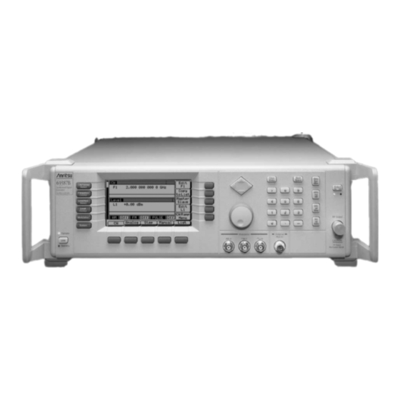
- Page 14 Figure 1-1. Series 693XXB Synthesized High Performance Signal Generator...
-
Page 15: Scope Of Manual
SCOPE OF MANUAL This manual provides general information, installation, and operating information for the Anritsu Series 693XXB Synthesized High Perform- ance Signal Generator. (Throughout this manual, the terms 693XXB and signal generator will be used interchangeably to refer to the in- strument.) Manual organization is shown in the table of contents. - Page 16 GENERAL 693XXB INFORMATION MODELS Table 1-1. Series 693XXB Models Output Power 693XXB Output Power Frequency Output Power w/Electronic Model w/Step Attenuator Step Attenuator 69317B 0.01 – 8.4 GHz +13.0 dBm +11.0 dBm +9.0 dBm 69337B 2.0 – 20.0 GHz +13.0 dBm +11.0 dBm +3.0 dBm 69347B...
-
Page 17: Identification Number
IDENTIFICATION INFORMATION NUMBER IDENTIFICATION All Anritsu instruments are assigned a unique six-digit ID number, such as “875012.” The ID number is imprinted on a decal that is af- NUMBER fixed to the rear panel of the unit. Special-order instrument configura- tions also have an additional special serial number tag attached to the rear panel of the unit. -
Page 18: Maintenance Manual
The Anritsu part number for the Main- tenance Manual is 10370-10351. The following options are available. OPTIONS Option 1, Rack Mounting. Rack mount kit containing a set of track slides (90°... - Page 19 (Not available in combination with Option 6 or 8.) Option 8, Internal Power Meter. Adds an internal power meter that is compatible with Anritsu 560-7, 5400-71, or 6400-71 series de- tectors. (Not available in combination with Option 7.) Option 9, Rear Panel RF Output. Moves the RF output connector to the rear panel.
-
Page 20: Performance Specifications
External Mixer: Option 91 (26.5 to 40 GHz) Option 92 (40 to 60 GHz) Option 93 (60 to 90 GHz) Power Meter, Range: –30 to +20 dBm Anritsu Models ML2437A or ML2438A, with (1mW to 100 mW) with Power Power Sensors: Sensors MA2474A (0.01 to 40 GHz) - Page 21 Chapter 2 Installation Table of Contents INTRODUCTION ....2-3 INITIAL INSPECTION ....2-3 PREPARATION FOR USE .
-
Page 22: Introduction
Anritsu Customer Service. If either the shipping container is damaged or the cushioning material shows signs of stress, notify the carrier as well as Anritsu. Keep the shipping materials for the carrier's inspec- tion. 693XXB OM... -
Page 23: Preparation For Use
PREPARATION INSTALLATION FOR USE PREPARATION FOR USE Preparation for use consists of checking that the rear panel line volt- age selector switch is set for the correct line voltage and connecting the signal generator to the power source. The following paragraphs provide these procedures along with information about power require- ments, warmup times, and the operating environment. -
Page 24: Standby Operation
PREPARATION INSTALLATION FOR USE Line Fuse Line Voltage Selector Switch GPIB Connector Figure 2-1. Signal Generator Rear Panel showing Power Connection Standby Whenever the signal generator is not being used it Operation should be left connected to the power source and placed in standby. -
Page 25: Warmup Time
PREPARATION INSTALLATION FOR USE Warmup Time From Standby–When placing the 693XXB in op- eration from stand-by, allow 30 minutes warmup to assure stable operation. From a Cold Start (0°C)–The signal generator re- quires approximately 120 hours (5 days) of warm up to achieve specified frequency stability with aging. -
Page 26: Gpib Setup And Interconnection
This interconnection is via a standard GPIB cable. The Anritsu Part number for such a cable is 2000-1, -2, or -4 (1, 2, or 4 meters in length). Setting the The default GPIB address is 5. - Page 27 GPIB SETUP AND INSTALLATION INTERCONNECTION Now press the menu soft-key Config . The System Configuration Menu (below) is displayed. To go to the Configure GPIB menu from this menu, press the menu soft-key GPIB . The Configure GPIB Menu (below) is displayed. Press the menu soft-key GPIB Address to change the current GPIB address of the signal generator.
-
Page 28: Selecting The Line Terminator
GPIB SETUP AND INSTALLATION INTERCONNECTION Selecting the Data is delimited on the GPIB by either the carriage Line return (CR) ASCII character or both the carriage re- Terminator turn and line feed (CR/LF) ASCII characters. Which character is used depends upon the requirements of the system controller. -
Page 29: Rack Mounting Kit Installation
RACK MOUNTING KIT INSTALLATION INSTALLATION RACK MOUNTING KIT The rack mounting kit (Option 1) contains a set of track slides (90° tilt capability), mounting ears, and front panel handles for mounting the INSTALLATION signal generator in a standard equipment rack. The following proce- dure provides instructions for installing the rack mounting hardware on to the instrument. - Page 30 Step 7 Insert two green-headed screws through (Anritsu P/N 2000-560) to avoid the holes near the rear of the slide assem- damage to the instrument. bly and into the metric tapped holes in the side of the instrument.
- Page 31 RACK MOUNTING KIT INSTALLATION INSTALLATION Step 10 Place the right side inner slide assembly onto the instrument case with the handle towards the front of the instrument. Step 11 Insert two green-headed screws through the holes in the slide assembly behind the handle and into the metric tapped holes in the side of the instrument.
-
Page 32: Preparation For Storage/Shipment
Seal the carton by using either shipping tape or an industrial stapler. Address the Container. If the instrument is being returned to Anritsu for service, mark the address of the appropriate Anritsu service center (Table 2-1) and your return address on the carton in one or more prominent locations. - Page 33 ANRITSU INSTALLATION SERVICE CENTERS Table 2-1. ANRITSU Service Centers UNITED STATES FRANCE JAPAN ANRITSU COMPANY ANRITSU S.A ANRITSU CUSTOMER SERVICE LTD. 490 Jarvis Drive 9 Avenue du Quebec 1800 Onna Atsugi-shi Morgan Hill, CA 95037-2809 Zone de Courtaboeuf Kanagawa-Prf. 243 Japan...
- Page 34 Chapter 3 Local (Front Panel) Operation Table of Contents INTRODUCTION ....3-5 FRONT PANEL LAYOUT....3-6 Line Key .
- Page 35 Table of Contents (Continued) SWEEP FREQUENCY OPERATION ..3-26 Analog Sweep Mode ....3-26 Selecting Analog Sweep Mode..3-26 Setting Sweep Time .
- Page 36 Table of Contents (Continued) 3-12 SIGNAL MODULATION ....3-73 Amplitude Modulation Operating Modes ..3-73 Providing Amplitude Modulation ..3-73 Frequency Modulation Operating Modes .
-
Page 37: Introduction
Chapter 3 Local (Front Panel) Operation INTRODUCTION This chapter provides information and instructions on operating the Series 693XXB Synthesized High Performance Signal Generator using the front panel controls. It contains the following: Illustrations and diagrams of the front panel, data display area, and data entry area that identify and describe all front panel controls, inputs, and outputs. -
Page 38: Line Key
LOCAL (FRONT FRONT PANEL PANEL) OPERATION LAYOUT FRONT PANEL LAYOUT The 693XXB front panel is divided into two main areas—the data dis- play area and the data entry area. The following paragraphs provide a brief description of the front panel controls, inputs, outputs, data dis- play, and data entry areas as shown in Figure 3-1. -
Page 39: Data Entry Area
LOCAL (FRONT FRONT PANEL PANEL) OPERATION LAYOUT Data Entry The data entry area consists of data entry keys and Area controls that provide for (1) changing values for each 693XXB parameter, and (2) terminating the value entry and assigning the appropriate units (GHz, MHz, dBm, etc.). -
Page 40: Data Display Area
LOCAL (FRONT DATA DISPLAY PANEL) OPERATION AREA DATA DISPLAY AREA The data display area consists of the data display and the surrounding menu keys. The data display is a dot matrix liquid crystal display (LCD) that provides 16 lines of 40 characters each. Information is presented on the LCD in the form of menu displays. -
Page 41: Menu Display Format
LOCAL (FRONT DATA DISPLAY PANEL) OPERATION AREA Menu Display The menu display is divided into specific areas that Format show the frequency, power level, and modulation in- formation for the current instrument setup. Menu labels for the current menu's soft-keys appear along the bottom and right side of the display. -
Page 42: Menu Keys
LOCAL (FRONT DATA DISPLAY PANEL) OPERATION AREA most cases, when a soft-key is pressed, its menu la- bel changes appearance to visually show the On/Off condition. Window Display A window display that overlays a portion of the cur- rent menu display is used to (1) show the parameter being edited;... - Page 43 LOCAL (FRONT DATA DISPLAY PANEL) OPERATION AREA quency sweep. In the Level Sweep mode, this menu lets you select the power sweep range parameters to use. MODULATION—This menu provides you with access to sub-menus that let you select the type of signal modulation (AM, FM, FM, or Pulse) and control the option settings for each type.
-
Page 44: Data Entry Area
LOCAL (FRONT DATA ENTRY PANEL) OPERATION AREA DATA ENTRY AREA The value of a selected 693XXB parameter can be changed using the rotary data knob and/or keys of the data entry area. Each element of the data entry area is identified in Figure 3-3 and described in the fol- lowing paragraphs. - Page 45 LOCAL (FRONT DATA ENTRY PANEL) OPERATION AREA Rotary Data Knob The rotary data knob can be used to change the value of a parameter that is open for editing. The cursor is moved under the open parameter using the < and > pads of the cursor control key. Then, by slowly turning the knob clockwise or counter- clockwise the value of the parameter is increased or decreased by the unit size.
-
Page 46: Instrument Start-Up
LOCAL (FRONT INSTRUMENT PANEL) OPERATION START-UP INSTRUMENT START-UP Now that you have familiarized yourself with the layout of the signal generator's front panel controls and data display, you are ready to be- gin operating the instrument. Begin by powering it up. Powering Up Connect the 693XXB to an ac power source by fol- the 693XXB... -
Page 47: Self-Testing The 693Xxb
LOCAL (FRONT INSTRUMENT PANEL) OPERATION START-UP Self-Testing The 693XXB firmware includes internal diagnostics the 693XXB that self-test the instrument. These self-test diag- nostics perform a brief go/no-go test of most of the PCBs and other internal assemblies. If the signal generator fails self-test, an error message is dis- played on the data display. - Page 48 LOCAL (FRONT RESET (DEFAULT) PANEL) OPERATION PARAMETERS Table 3-1. Series 693XXB Reset (Default) Parameters (1 of 2) FREQUENCY PARAMETERS (GHz) MODEL NUMBER M0 M1 M2 M3 M4 M5 M6 M7 M8 M9 69317B 3.5 2.0 8.4 2.0 5.0 8.0 8.4 8.4 8.4 8.4 3.5 2.0 8.4 2.0 5.0 8.4 8.4 8.4 8.4 8.4 1.0 69337B 3.5 2.0 20.0 2.0 5.0 8.0 11.0 14.0 17.0 20.0 3.5 2.0 20.0 2.0 5.0 8.0 11.0 14.0 17.0 20.0 1.0 69347B...
- Page 49 LOCAL (FRONT RESET (DEFAULT) PANEL) OPERATION PARAMETERS Table 3-1. Series 693XXB Reset (Default) Parameters (2 of 2) STEP SWEEP LEVEL SWEEP MODEL SWEEP LEVEL NUMBER TIME NUMBER OF NUMBER OF OFFSET DWELL TIME DWELL TIME STEPS STEPS 69317B 50 ms 1 ms 50 ms 0.0 dB...
-
Page 50: Entering Data
LOCAL (FRONT ENTERING PANEL) OPERATION DATA ENTERING DATA Before proceeding to the various modes of signal generator operation, you need to know how to enter data from the front panel. Entering data refers to changing a parameter's value by editing its current value or entering a new value to replace the current value. -
Page 51: Editing The Current Value
LOCAL (FRONT ENTERING PANEL) OPERATION DATA Editing the To change the current value of a parameter by edit- Current Value ing, you can use either the cursor control key or the rotary data knob. Using the Cursor Control Key Using the < and > pads of the cursor control key, move the cursor under the digit where you want to Cursor Control... -
Page 52: Entering A New Value
LOCAL (FRONT ENTERING PANEL) OPERATION DATA Entering a To change the current value of a parameter by en- New Value tering a new value for the parameter, use the data entry keypad and termination keys. As soon as you press one of the keys on the data entry keypad, the current parameter display clears for entry of a new value. -
Page 53: Cw Frequency Operation
LOCAL (FRONT CW FREQUENCY PANEL) OPERATION OPERATION CW FREQUENCY One of the signal generator's major functions is to produce discrete CW frequencies across the frequency range of the instrument. The fol- OPERATION lowing paragraphs describe how to place the 693XXB in the CW fre- quency mode, select a CW frequency and power level for output, and activate the CW ramp. -
Page 54: Selecting A Cw Frequency
LOCAL (FRONT CW FREQUENCY PANEL) OPERATION OPERATION Selecting a There are several ways to select a CW frequency for output. You can (1) edit the current frequency, (2) Frequency enter a new frequency, or (3) select one of the 20 pre- set frequency parameters. - Page 55 LOCAL (FRONT CW FREQUENCY PANEL) OPERATION OPERATION Frequency List–To go to the Frequency List menu (below), press Freqs List . This menu lets you tag, edit, or output a frequency from the list. Use the cursor control key to select a frequency from the frequency list.
-
Page 56: Selecting A Power Level
LOCAL (FRONT CW FREQUENCY PANEL) OPERATION OPERATION Scanning Tagged Frequencies–To go to the Tagged Frequencies menu (below) from the CW Fre- quency Control menu, press Tag Freq Menu . This menu lets you select the tagged frequencies for output using the Scan Up and Scan Dn keys. Return to the CW Frequency Control menu by pressing Previous Menu . -
Page 57: Cw Ramp
LOCAL (FRONT CW FREQUENCY PANEL) OPERATION OPERATION CW Ramp When active, the signal generator's CW ramp pro- vides a repetitive 0V to 10V ramp output to the rear panel HORIZ OUT BNC connector and AUX I/O con- nector. The CW ramp is used to drive a scalar ana- lyzer display. -
Page 58: Sweep Frequency Operation
LOCAL (FRONT SWEEP FREQUENCY PANEL) OPERATION OPERATION SWEEP FREQUENCY The signal generator can generate broad (full range) and narrow band sweeps across the frequency range of the instrument. The 693XXB has OPERATION four sweep frequency modes—analog sweep, step sweep, manual sweep, and list sweep. -
Page 59: Setting Sweep Time
LOCAL (FRONT SWEEP FREQUENCY PANEL) OPERATION OPERATION This menu lets you perform the following: Select a sweep range (edit the sweep start and stop frequency parameters). Go to the sweep ramp menu (set the sweep time and select a sweep trigger). Select an output power level for the sweep. -
Page 60: Selecting A Sweep Trigger
LOCAL (FRONT SWEEP FREQUENCY PANEL) OPERATION OPERATION Selecting a There are three modes of sweep triggering provided Sweep for analog sweep and step sweep—automatic, exter- Trigger nal, and single. The sweep trigger is selectable from the trigger menu. The following is a description of each mode. -
Page 61: Step Sweep Mode
LOCAL (FRONT SWEEP FREQUENCY PANEL) OPERATION OPERATION Step Sweep In step sweep frequency mode, the output frequency Mode changes in discrete, synthesized steps between selected start and stop frequencies. Step sweeps can be from a low frequency to a high frequency or from a high frequency to a low frequency. - Page 62 LOCAL (FRONT SWEEP FREQUENCY PANEL) OPERATION OPERATION The step size range is 1 kHz (0.1 Hz with Option 11) to the full frequency range of the instrument; the number of steps range is 1 to 10,000. If the step size does not divide into the frequency range, the last step is truncated.
- Page 63 LOCAL (FRONT SWEEP FREQUENCY PANEL) OPERATION OPERATION Open the parameter you wish to change, then edit the current value using the cursor control key or the rotary data knob or enter a new value using the key pad and appropriate termination key. When you have finished setting the open parameter, close it by pressing its menu soft-key or make another menu selection.
-
Page 64: Manual Sweep Mode
LOCAL (FRONT SWEEP FREQUENCY PANEL) OPERATION OPERATION Manual In manual sweep frequency mode, the output fre- Sweep Mode quency can be manually tuned in phase-locked steps between the selected start and stop frequencies us- ing the rotary data knob. As the knob is turned, the current output frequency is displayed on the data display as Fm. -
Page 65: Selecting A Sweep Range
LOCAL (FRONT SWEEP FREQUENCY PANEL) OPERATION OPERATION Selecting a Selecting a sweep range involves choosing a start Sweep Range and a stop frequency for the frequency sweep. The sweep range selection process is identical for the analog sweep, step sweep, and manual sweep fre- quency modes. - Page 66 LOCAL (FRONT SWEEP FREQUENCY PANEL) OPERATION OPERATION Selecting a Preset Sweep Range There are four preset sweep range parameters, se- lectable in the analog sweep, step sweep, and man- ual sweep frequency modes. The following is a description of each preset sweep range. F1-F2–provides a frequency sweep between the start frequency, F1, and the stop frequency, F2.
-
Page 67: Selecting A Power Level
LOCAL (FRONT SWEEP FREQUENCY PANEL) OPERATION OPERATION Setting a Preset Sweep Range–At the menu, select the sweep range (F1-F2, F3-F4, F5-dF, or F6-dF) that you wish to set. The menu then displays the current frequency parameters for the selected sweep range. Now use the menu edit soft-keys to open the frequency parameters for editing. -
Page 68: Frequency Markers
LOCAL (FRONT SWEEP FREQUENCY PANEL) OPERATION OPERATION Frequency The 693XXB provides up to 20 independent, pre- Markers settable markers, F0-F9 and M0-M9, that can be used in the analog and step sweep frequency modes for precise frequency identification. Marker fre- quency accuracy is the same as sweep frequency ac- curacy. - Page 69 LOCAL (FRONT SWEEP FREQUENCY PANEL) OPERATION OPERATION Use the cursor control key to select a frequency parameter from the marker list. The selected fre- quency parameter is highlighted in reverse video and displayed in full below the marker list. Editing a Marker List Frequency If you want to change a selected marker list fre- quency parameter's value, press Edit .
-
Page 70: Selecting Alternate Sweep Mode
LOCAL (FRONT SWEEP FREQUENCY PANEL) OPERATION OPERATION Selecting In alternate sweep frequency mode, the 693XXB's Alternate output frequency sweeps alternately between any Sweep Mode two sweep ranges in analog sweep or any two sweep ranges in step sweep. The process of selecting and activating the alternate sweep is identical for both analog sweep and step sweep frequency modes. - Page 71 LOCAL (FRONT SWEEP FREQUENCY PANEL) OPERATION OPERATION Now, press Previous Menu to return to the Step Sweep Menu display (or the Analog Sweep Menu display if operating in analog sweep frequency mode). Notice the changes to the Step Sweep Menu display (below).
- Page 72 LOCAL (FRONT SWEEP FREQUENCY PANEL) OPERATION OPERATION When you are done selecting the alternate sweep range, press Previous Menu to return to the Alter- nate Sweep menu. Selecting an Alternate Sweep Power Level To go to the Alternate Level menu (shown below) from the Alternate Sweep menu, press Alt Level .
-
Page 73: List Sweep Mode
LOCAL (FRONT SWEEP FREQUENCY PANEL) OPERATION OPERATION List Sweep In list sweep frequency mode, the RF output is a Mode step sweep of up to 2000 phase-locked, non- sequential frequencies. Each frequency can have a different power level setting. The list index (0 thru 1999) identifies each frequency/power level set in the list. -
Page 74: Selecting List Sweep Mode
LOCAL (FRONT SWEEP FREQUENCY PANEL) OPERATION OPERATION Selecting List To place the 693XXB in list sweep frequency mode, Sweep Mode press the main menu key CW/SWEEP SELECT At the resulting menu display, press List . The List Sweep menu (below) is displayed. This menu lets you perform the following: Go to the Edit List menus (edit list index fre- quency and power level parameters and insert... -
Page 75: Editing The List
LOCAL (FRONT SWEEP FREQUENCY PANEL) OPERATION OPERATION Performing List Calculations The PreCalc List soft-key initiates a process that examines every index in the list and performs all the calculations necessary to set the frequency and power levels. The soft-key does not have to be pressed every time the list changes. - Page 76 LOCAL (FRONT SWEEP FREQUENCY PANEL) OPERATION OPERATION List Frequency Edit–to go to the List Frequency Edit menu (below), press Edit Freq . This menu lets you scroll through the list frequencies and edit se- lected frequencies. The menu displays a total of 20 frequencies. The index range of the displayed frequencies is shown at the top of the list.
- Page 77 LOCAL (FRONT SWEEP FREQUENCY PANEL) OPERATION OPERATION Press Edit to edit the highlighted power level or en- ter a new power level. Press Page Up to scroll the displayed power levels to the next 10 in the list. Press Page Down to scroll the displayed power levels to the previous 10 in the list.
-
Page 78: Selecting A List Sweep Range
LOCAL (FRONT SWEEP FREQUENCY PANEL) OPERATION OPERATION Copying Data from the CW Menu An easy method of entering frequency and power level information into the current list index is to copy the data from the CW menu. First, go to the main List Sweep menu and press the List Index soft-key to open the list index parameter. -
Page 79: Selecting A List Sweep Trigger
LOCAL (FRONT SWEEP FREQUENCY PANEL) OPERATION OPERATION Press Start Index to open the list sweep start index parameter. Press Stop Index to open the list sweep stop index parameter. Press Dwell Time to open the dwell-time-per-step parameter. Open the parameter you wish to change, then edit the current value using the cursor control key or ro- tary data knob or enter a new value using the key pad and appropriate termination key. - Page 80 LOCAL (FRONT SWEEP FREQUENCY PANEL) OPERATION OPERATION To go to the List Sweep Trigger menu (below) from the Sweep menu, press Trigger . To select a sweep trigger mode, press its menu soft key. A message showing the trigger mode selected appears on the right side of the frequency title bar.
-
Page 81: Fixed Power Level Operation
LOCAL (FRONT FIXED POWER PANEL) OPERATION LEVEL OPERATION FIXED POWER LEVEL The 693XXB provides leveled output power over a maximum range of up to 33 dB (up to 149 dB with Option 2) for CW and sweep frequency OPERATION operations. Instruments with Option 15B provide leveled output power over a maximum range of up to 27 dB (up to 141 dB with Op- tion 2). - Page 82 LOCAL (FRONT FIXED POWER PANEL) OPERATION LEVEL OPERATION and appropriate terminator key. To close the open NOTE power level parameter, press Edit L1 or make an- When Linear power level units are other menu selection. selected, use the following termi- nator keys for power level data Selecting a Preset Power Level entries:...
- Page 83 LOCAL (FRONT FIXED POWER PANEL) OPERATION LEVEL OPERATION Use the cursor control key to select a power level from the level list. The selected power level is high- lighted in reverse video and displayed in full below the level list. Press Tag to mark a selected power level (place an L in front of it).
-
Page 84: Level Offset
LOCAL (FRONT FIXED POWER PANEL) OPERATION LEVEL OPERATION Level Offset Level offset lets you compensate for a device on the signal generator's output that alters the RF output power level at the point of interest. For example, the power level at the test device may be less or more than the displayed power level because of the loss through an external transmission line or the gain of an amplifier located between the 693XXB RF output... -
Page 85: Power Level Sweep Operation
LOCAL (FRONT POWER LEVEL PANEL) OPERATION SWEEP OPERATION 3-10 POWER LEVEL SWEEP The 693XXB provides leveled output power sweeps at CW frequencies and in conjunction with frequency sweeps (analog and step). Power OPERATION level sweeps can be from a high level to a low level or vice versa. Power level sweeps can be selected to be linear or logarithmic. -
Page 86: Power Level Sweep Operation
LOCAL (FRONT POWER LEVEL PANEL) OPERATION SWEEP OPERATION Setting CW There are two ways to set the size of each step of the Power Sweep CW power sweep—set the step size or set the Step Size and number of steps. The step size range is 0.01 dB Dwell Time (Log) or 0.001 mV (Linear) to the full power range of the instrument;... -
Page 87: Selecting A Cw Power Sweep Trigger
LOCAL (FRONT POWER LEVEL PANEL) OPERATION SWEEP OPERATION Selecting a There are three modes of triggering provided for the CW Power CW power sweep—automatic, external, and single. Sweep The sweep trigger is selectable from the CW Level Trigger Sweep Trigger menu. The following is a description of each trigger mode. -
Page 88: Selecting A Power Level Sweep Range
LOCAL (FRONT POWER LEVEL PANEL) OPERATION SWEEP OPERATION Selecting a Selecting a power level sweep range consists of Power Level choosing a start and stop level for the power level Sweep Range sweep. The power level sweep range selection pro- cess is identical for all power level sweep modes—... - Page 89 LOCAL (FRONT POWER LEVEL PANEL) OPERATION SWEEP OPERATION Selecting a Preset Power Level Sweep Range There are five preset power level sweep range pa- rameters selectable in the power level sweep modes. These preset power level sweep range parameters are L1-L2, L3-L4, L5-L6, L7-L8, and L9-L0. To select one of the preset power level sweep ranges from a Level Sweep menu, press the main menu key LEVEL...
-
Page 90: Selecting A Sweep Frequency / Step Power Mode
LOCAL (FRONT POWER LEVEL PANEL) OPERATION SWEEP OPERATION Selecting a In analog sweep frequency/step power mode or step Sweep Fre- sweep frequency/step power mode, a power level quency / Step step occurs after each frequency sweep. The power Power Mode level remains constant for the length of time re- quired to complete each frequency sweep. -
Page 91: Setting Power Level Step Size
LOCAL (FRONT POWER LEVEL PANEL) OPERATION SWEEP OPERATION Setting Power There are two ways to set the step size of the power Level Step level step that occurs after each frequency sweep Size —set the step size or set the number of steps. The step size range is 0.01 dB (Log) or 0.001 mV (Linear) to the full power range of the signal generator;... -
Page 92: Leveling Operations
LOCAL (FRONT LEVELING PANEL) OPERATION OPERATIONS 3-11 LEVELING The 693XXB generates leveled output power over a maximum range of up to 33 dB (up to 149 dB with Option 2). Instruments with Option OPERATIONS 15B provide leveled output power over a maximum range of up to 27 dB (up to 141 dB with Option 2). - Page 93 LOCAL (FRONT LEVELING PANEL) OPERATION OPERATIONS The ALC Mode menu lets you perform the following: Go to the leveling menu (select the ALC mode of operation). Go to the attenuation menu (decouple the attenuator, if equipped, from the ALC system and set the power level and attenuation).
- Page 94 LOCAL (FRONT LEVELING PANEL) OPERATION OPERATIONS Before going to the Leveling Menu from the ALC Mode menu, select whether the external ALC signal is to be connected to the front- or rear-panel EXT ALC IN connector. At the ALC Mode menu, press Ext ALC Front to select front panel input, or Ext ALC Rear to select rear panel input.
- Page 95 LOCAL (FRONT LEVELING PANEL) OPERATION OPERATIONS At the Leveling menu, pressing either Internal or Fixed Gain will turn off external leveling. Press Previous Menu to return to the ALC Mode menu. Fixed Gain In the fixed gain mode, the ALC is disabled. The RF Level DAC and step attenuator (if installed) are used to control the relative power level.
-
Page 96: Attenuator Decoupling
LOCAL (FRONT LEVELING PANEL) OPERATION OPERATIONS Attenuator In 693XXBs equipped with option 2 step attenua- Decoupling tors, the ALC and attenuator work in conjunction to provide leveled output power down to –140 dBm. In the normal (coupled) leveling mode, when the de- sired power level is set, the correct combination of ALC level and attenuator setting is determined by the instrument firmware. -
Page 97: Alc Power Slope
LOCAL (FRONT LEVELING PANEL) OPERATION OPERATIONS ALC Power The ALC power slope function lets you compensate Slope for system, cable, and waveguide variations due to changes in frequency. This is accomplished by line- arly increasing or decreasing power output as the frequency increases. - Page 98 LOCAL (FRONT LEVELING PANEL) OPERATION OPERATIONS Press Slope On/Off to activate the ALC power slope function. Press Edit Pivot to open the pivot point frequency parameter for editing. Edit the current frequency SLOPE using the cursor control key or rotary data knob or enter a new value using the keypad and appropriate When Power Slope is selected ON, termination key.
-
Page 99: User Cal (User Level Flatness Correction)
Up to five user level flatness correction power-offset tables from 2 to 801 frequency points/table can be created and stored in 693XXB memory for recall. The GPIB power meters supported are Anritsu Models ML2437A, ML2438A, and ML4803A and Hewlett-Packard Models 437B, 438A, and 70100A. - Page 100 LOCAL (FRONT LEVELING PANEL) OPERATION OPERATIONS Equipment Setup To create a power-offset table for user level flatness correction, connect the equipment (shown in Figure 3-4) as follows: Step 1 Using a GPIB cable, connect the Power Meter to the 693XXB. Step 2 Calibrate the Power Meter with the Power Sensor.
- Page 101 The new GPIB address will appear on the display. Press Pwr Mtr Select to select the power meter model being used. (Supported power meters are Anritsu ML2437A, ML2438A, and ML4803A and Hewlett-Packard 437B, 438A, and 70100A.) Press Previous Menu to return to the main Config- ure GPIB menu display.
- Page 102 LOCAL (FRONT LEVELING PANEL) OPERATION OPERATIONS Place the signal generator in a fixed power level mode by pressing the main menu key LEVEL/ALC SELECT At the resulting menu display, press Level . The 693XXB is now in fixed (non-swept) power level mode.
- Page 103 LOCAL (FRONT LEVELING PANEL) OPERATION OPERATIONS s range is 2 to 801.) When you have finished setting the open number-of-points parameter, close it by pressing Edit Points again or by making another menu selection. Now, press Start Cal to begin automatically taking power level correction information at each frequency point.
- Page 104 LOCAL (FRONT LEVELING PANEL) OPERATION OPERATIONS Erasing the Power-Offset Tables from Memory The power-offset tables are stored in non-volatile memory. A master reset is required to erase the con- tents of the tables and reprogram them with default data. To perform a master reset, proceed as follows: NOTE Step 1 With the 693XXB in standby, press and...
-
Page 105: Signal Modulation
LOCAL (FRONT SIGNAL PANEL) OPERATION MODULATION 3-12 The signal generator provides AM, FM, FM (Option 6), and pulse SIGNAL MODULATION modulation of the output signal using modulating signals from either the internal AM, FM, FM, and pulse generators or external sources. FM and FM are operationally exclusive;... - Page 106 LOCAL (FRONT SIGNAL PANEL) OPERATION MODULATION This menu lets you perform the following: Select the modulating signal source. Select the Linear AM or Log AM operating mode. Press Internal / External to select the source of the modulating signal. Internal selects the modulating signal from the internal AM generator;...
- Page 107 LOCAL (FRONT SIGNAL PANEL) OPERATION MODULATION This menu contains the internal AM status window that shows the current menu selections. This menu lets you perform the following: Turn AM on and off. Set the AM Depth. Set the AM Rate. Go to the Modulation Waveform Selection menu.
- Page 108 LOCAL (FRONT SIGNAL PANEL) OPERATION MODULATION Press Previous Menu to return to the main AM Status Menu display. External AM Source To provide amplitude modulation of the output sig- nal using a modulating signal from an external source, first set up the external signal generator and connect it to either the 693XXB front or rear panel AM IN connector.
- Page 109 LOCAL (FRONT SIGNAL PANEL) OPERATION MODULATION Linear and 0 dB/V to 25 dB/V in Log. To close the open AM Sensitivity parameter, press Edit Sens or make another menu selection. Press 600W / 50W to select the input impedance of the input connector.
-
Page 110: Frequency Modulation Operating Modes
LOCAL (FRONT SIGNAL PANEL) OPERATION MODULATION Frequency The signal generator has four FM operating modes Modulation —Locked, Locked Low-Noise, Unlocked Narrow, and Operating Unlocked Wide. In the Locked and Locked Low- Modes Noise FM modes, frequency modulation of the out- put signal is accomplished by summing the modu- lating signal into the FM control path of the YIG phase-lock loop. - Page 111 LOCAL (FRONT SIGNAL PANEL) OPERATION MODULATION Now, press the menu soft-key More . The additional FM Status Menu (below) is displayed. This menu lets you perform the following: Select the modulating signal source. Go to the FM Mode Selection menu. Press Int / Ext to select the source of the modulating signal.
- Page 112 LOCAL (FRONT SIGNAL PANEL) OPERATION MODULATION Internal FM Source Once you have pressed Int / Ext to select the inter- nal FM generator as the modulating signal source, the Internal FM Status Menu (below) is displayed. This menu contains the internal FM status window that shows the current menu selections.
- Page 113 LOCAL (FRONT SIGNAL PANEL) OPERATION MODULATION Press Mod. Wave to go to the Modulation Wave- form Selection Menu (below). This menu displays the modulation waveforms (on sine wave the left) that are available from the FM generator. Use the cursor control key to highlight the desired square wave modulation waveform, then press Select to select it.
- Page 114 LOCAL (FRONT SIGNAL PANEL) OPERATION MODULATION Turn FM on and off. Max Rate: xxx MHz Set the FM Sensitivity. In units with Option 21B operating Select the input impedance (600W or 50W) of at frequencies from 10 MHz to the input connector. £2.2 GHz, this advisory message is Select the input connector (front panel or rear displayed for all FM modes except...
-
Page 115: Phase Modulation Operating Modes
LOCAL (FRONT SIGNAL PANEL) OPERATION MODULATION Phase When Option 6 is added to the instrument, the Modulation 693XXB provides phase modulation (FM) of the Operating output signal using modulating signals from either its internal FM generator or an external source. Modes The 693XXB has two FM operating modes—Narrow FM and Wide FM. - Page 116 LOCAL (FRONT SIGNAL PANEL) OPERATION MODULATION This menu lets you perform the following: Select the modulating signal source. Select the FM operating mode (Narrow or Wide). Press Int / Ext to select the source of the modulating signal. Int selects the modulating signal from the in- ternal FM generator;...
- Page 117 LOCAL (FRONT SIGNAL PANEL) OPERATION MODULATION Press Edit Dev. to open the FM Deviation parame- ter, then edit the current value using the cursor con- trol key or rotary data knob or enter a new value This error message is displayed when the internal FM actual devia- using the keypad and the GHz/Sec/dBm terminator key.
- Page 118 LOCAL (FRONT SIGNAL PANEL) OPERATION MODULATION The External FM Status Menu (below) is then dis- played. Max Rate: xxx MHz This menu contains the external FM status window In units with Option 21B operating that shows the current menu selections and the at frequencies from 10 MHz to measured FM Deviation (The FM deviation meas- £2.2 GHz, this advisory message is...
-
Page 119: Pulse Modulation Operating Modes
LOCAL (FRONT SIGNAL PANEL) OPERATION MODULATION Pulse The 693XXB signal generator provides pulse modu- Modulation lation of the output signal using modulating signals Operating from either its internal pulse generator or an exter- Modes nal source. The internal pulse generator has four pulse modes— single, doublet (double pulse), triplet (triple pulse), and quadruplet (quadruple pulse). -
Page 120: Providing Pulse Modulation
LOCAL (FRONT SIGNAL PANEL) OPERATION MODULATION Providing The following are the menu selections to provide Pulse pulse modulation of the output signal using a modu- Modulation lating signal from both the internal pulse generator and an external source. Internal Pulse Source Press MODULATION . - Page 121 LOCAL (FRONT SIGNAL PANEL) OPERATION MODULATION then press Edit . Edit the current value using the NOTE cursor control key or rotary data knob or enter a Pulse Delay (D1) is only active new value using the keypad and the appropriate when Delayed, Triggered w/delay, terminator key.
- Page 122 LOCAL (FRONT SIGNAL PANEL) OPERATION MODULATION This menu displays the pulse modes (Single, Dou- blet, Triplet, and Quadruplet) that are available from the pulse generator. Use the cursor control key to highlight the desired pulse mode, then select it by pressing Select .
- Page 123 Free Run–The pulse generator produces Single, Doublet, Triplet, or Quadru- plet pulse modulation waveforms at the internal pulse repetition rate. Pulse de- FREE RUN lay (D1) is not available in this trigger mode. PULSE SYNC OUT Delayed–The pulse generator produces Single, Doublet, Triplet, or Quadruplet pulse modulation waveforms delayed by pulse delay (D1) at the internal pulse repetition rate.
- Page 124 LOCAL (FRONT SIGNAL PANEL) OPERATION MODULATION At the additional Internal Pulse Status menu, press Config. to go to the Internal Pulse Configuration Menu (below). This menu lets you perform the following: Select the display of PRF or Period on the In- ternal Pulse status display.
- Page 125 LOCAL (FRONT SIGNAL PANEL) OPERATION MODULATION Stepped Delay Mode The Stepped Delay Mode lets you automatically in- crement or decrement the Pulse Delay 1 (D1) value according to step delay parameters. The mode is only available when the Delayed or Triggered w/de- lay triggering mode is selected.
- Page 126 LOCAL (FRONT SIGNAL PANEL) OPERATION MODULATION This menu lets you set the length of time a Delay 1 (D1) time is applied before it is incremented or dec- remented by the step size. Press Step Time to open the dwell-time-per-step parameter, then edit the current value using the cursor control key or rotary data knob or enter a new value using the keypad and appropriate termi-...
- Page 127 LOCAL (FRONT SIGNAL PANEL) OPERATION MODULATION External Pulse Source To provide pulse modulation of the output signal using a modulating signal from an external source, first set up the external pulse generator and connect it to either the 693XXB front or rear panel PULSE TRIGGER IN connector.
-
Page 128: System Configuration
LOCAL (FRONT SYSTEM PANEL) OPERATION CONFIGURATION 3-13 SYSTEM The system configuration function provides menus that let you set or select instrument configuration items; for example, display intensity, CONFIGURATION polarity of blanking and video marker outputs, RF on or off during re- trace or between steps, frequency scaling, GPIB operating parameters, external interface language, and increment sizes for frequency, power level, and time parameters. -
Page 129: Configuring The Front Panel
LOCAL (FRONT SYSTEM PANEL) OPERATION CONFIGURATION Configuring Configuring the front panel of the signal generator the Front involves adjusting the intensity level of the data dis- Panel play for ease of viewing. To go to the Configure Front Panel menu from the System Configuration menu, press Front Panel . -
Page 130: Configuring The Rear Panel
LOCAL (FRONT SYSTEM PANEL) OPERATION CONFIGURATION Configuring Configuring the rear panel of the signal generator the Rear consists of selecting the polarity of the retrace Panel blanking, bandswitch blanking, retrace penlift, and video marker outputs. To go to the Configure Rear Panel menu from the System Configuration menu, press Rear Panel . -
Page 131: Configuring The Rf
LOCAL (FRONT SYSTEM PANEL) OPERATION CONFIGURATION Configuring Configuring the RF of the 693XXB involves the fol- the RF lowing: Selecting whether the RF should be on or off during retrace. Selecting whether the RF should be on or off during frequency switching in CW, step sweep, and list sweep modes. - Page 132 LOCAL (FRONT SYSTEM PANEL) OPERATION CONFIGURATION Additional Configure RF Menu When you press More , the Additional Configure RF Menu (below) is displayed. Press Reset State to select RF on or off at reset. The display will reflect your selection. Frequency Scaling –...
-
Page 133: Configuring The Gpib
LOCAL (FRONT SYSTEM PANEL) OPERATION CONFIGURATION Configuring The GPIB configuration menus let you perform the the GPIB following: Set the GPIB address and select the GPIB line terminator for the signal generator. Turn on the source lock mode for operation with a Model 360B Vector Network Analyzer. - Page 134 CONFIGURATION Press SS Mode to turn on the source lock mode for SS MODE operation with a Anritsu Model 360B Vector Net- work Analyzer. (Refer to paragraph 7-4 for informa- When SS Mode is selected on, this tion pertaining to operating the 693XXB with a message is displayed (in the fre- 360B VNA.) Press SS Mode again to turn off the...
- Page 135 LOCAL (FRONT SYSTEM PANEL) OPERATION CONFIGURATION Hewlett-Packard 437B, 438A, and 70100A.) Press Native SCPI to select the external interface language to be used for remote operation of the 693XXB. (Language selection is only available on in- struments that have Option 19 installed.) Press More to go to the Second Additional Config- ure GPIB menu for more selections.
-
Page 136: Setting Increment Sizes
LOCAL (FRONT SYSTEM PANEL) OPERATION CONFIGURATION Setting The Increment menu lets you set the incremental Increment size for editing frequency, power level, and time pa- Sizes rameters. When the increment mode is selected on, these parameter values will increase or decrease by the set amount each time the Ù... -
Page 137: Saving/Recalling Instrument Setups
LOCAL (FRONT SAVING/RECALLING PANEL) OPERATION INSTRUMENT SETUPS 3-14 SAVING/RECALLING The 693XXB offers the capability to store up to ten complete front panel setups. The setups are numbered 0 through 9. The following INSTRUMENT SETUPS paragraphs describe how to save and recall front panel setups. Saving Once you have decided that an instrument setup Setups... -
Page 138: Erasing Stored Setups
LOCAL (FRONT SAVING/RECALLING PANEL) OPERATION INSTRUMENT SETUPS Erasing The front panel setups are stored in non-volatile Stored Setups memory. A master reset is required to erase the con- tents of the setups and reprogram them with default data. To perform a master reset, proceed as follows: NOTE Step 1 With the 693XXB in standby, press and... -
Page 139: Secure Operation
LOCAL (FRONT SECURE PANEL) OPERATION OPERATION 3-15 SECURE OPERATION The 693XXB can be operated in a secure mode of operation. In this se- cure mode, the display of all frequency, power level, and modulation parameters is disabled during both local (front panel) and remote (GPIB) operations. -
Page 140: Reference Oscillator Calibration
LOCAL (FRONT REFERENCE PANEL) OPERATION OSCILLATOR CALIBRATION 3-16 REFERENCE The reference oscillator calibration function lets you calibrate the internal 100 MHz crystal reference oscillator of the 693XXB using an OSCILLATOR CALIBRATION external 10 MHz, 0 to +10 dBm reference signal. NOTE Before beginning calibration, always let the 693XXB warm up for a minimum of... - Page 141 LOCAL (FRONT REFERENCE PANEL) OPERATION OSCILLATOR CALIBRATION When Proceed is pressed, the date parameter opens for data entry. Using the key pad, enter the current date (in any desired format). Then, press any terminator key. The Calibration Status Menu display changes to in- dicate calibration is in progress.
-
Page 142: Internal Power Measurement
LCD. The power measurement function has a range of +16 dBm to –35 dBm and is compatible with Anritsu 560-7, 5400-71, and 6400-71 series de- tectors. To make a measurement of the power from a test... -
Page 143: Chapter 4 Local Operation-Menu Maps
Chapter 4 Local Operation–Menu Maps Table of Contents INTRODUCTION ....4-3 MENU MAP DESCRIPTION ... . . 4-3... -
Page 144: Introduction
Chapter 4 Local Operation–Menu Maps INTRODUCTION This chapter provides menu maps that support the 693XXB front panel operating instructions found in Chapter 3. It includes menu maps for all of the frequency, power level, and modulation modes of op- eration. In addition, a menu map for system configuration is also pro- vided. -
Page 145: Sample Menu Map
LOCAL OPERATION SAMPLE –MENU MAPS MENU MAP Figure 4-1. Sample Menu Map (Annotated) 693XXB OM... -
Page 146: Cw Frequency Mode Menu Map
LOCAL OPERATION –MENU MAPS FREQUENCY MODE NOTES 1. Refer to Chapter 3, paragraph 3-7 for CW Frequency Mode operating instruc- tions. 2. Refer to Chapter 7, paragraph 7-2 for Master-Slave operating instructions. Figure 4-2. CW Frequency Mode Menu Map 693XXB OM... -
Page 147: Analog Sweep Frequency Mode Menu Map
LOCAL OPERATION ANALOG SWEEP –MENU MAPS FREQUENCY MODE NOTE 1. Refer to Chapter 3, paragraph 3-8 for Analog Sweep Frequency Mode oper- ating instructions. Figure 4-3. Analog Sweep Frequency Mode Menu Map 693XXB OM... -
Page 148: Step Sweep Frequency Mode Menu Map
LOCAL OPERATION STEP SWEEP –MENU MAPS FREQUENCY MODE NOTE 1. Refer to Chapter 3, paragraph 3-8 for Step Sweep Frequency Mode operat- ing instructions. Figure 4-4. Step Sweep Frequency Mode Menu Map 693XXB OM... -
Page 149: Manual Sweep Frequency Mode Menu Map
LOCAL OPERATION MANUAL SWEEP –MENU MAPS FREQUENCY MODE NOTE 1. Refer to Chapter 3, paragraph 3-8 for Manual Sweep Frequency Mode operat- ing instructions. Figure 4-5. Manual Sweep Frequency Mode Menu Map 693XXB OM... -
Page 150: List Sweep Frequency Mode Menu Map
LOCAL OPERATION LIST SWEEP –MENU MAPS FREQUENCY MODE NOTE 1. Refer to Chapter 3, paragraph 3-8 for List Sweep Frequency Mode operating instructions. Figure 4-6. List Sweep Frequency Mode Menu Map 4-10 693XXB OM... -
Page 151: Fixed Power Level Mode Menu Map
LOCAL OPERATION FIXED POWER –MENU MAPS LEVEL MODE NOTE Refer to Chapter 3, paragraph 3-9 for Fixed Power Level Mode operating in- structions. Figure 4-7. Fixed Power Level Mode Menu 693XXB OM 4-11... -
Page 152: Cw Power Sweep Mode Menu Map
LOCAL OPERATION CW POWER –MENU MAPS SWEEP MODE NOTE Refer to Chapter 3, paragraph 3-10 for CW Power Sweep Mode operating instructions. Figure 4-8. CW Power Sweep Mode Menu 4-12 693XXB OM... -
Page 153: Sweep Frequency/Step Power Mode Menu Map
LOCAL OPERATION SWEEP FREQUENCY/ –MENU MAPS STEP POWER MODE NOTE Refer to Chapter 3, paragraph 3-10 for Sweep Frequency/Step Power Mode operating instructions. Figure 4-9. Sweep Frequency/Step Power Mode Menu Map 693XXB OM 4-13... -
Page 154: Leveling Modes Menu Map
LOCAL OPERATION LEVELING –MENU MAPS MODES Selects Internal ALC (Default Mode) CW/SWEEP SELECT Selects External ALC FREQUENCY CONTROL (External Detector Input) Selects Front Panel LEVEL/ALC External ALC Input Selects External ALC SELECT (Power Meter Input) LEVEL CONTROL Selects Rear Panel External ALC Input Selects ALC Off MODULATION... -
Page 155: Amplitude Modulation Mode Menu Map
LOCAL OPERATION AMPLITUDE –MENU MAPS MODULATION MODE INTERNAL AM SOURCE SELECTED Select Modulation Waveform CW/SWEEP AM On/Off SELECT FREQUENCY CONTROL Edit AM Depth LEVEL/ALC Edit AM Rate SELECT LEVEL CONTROL MODULATION SYSTEM Internal AM Source or External AM Source Log AM (0-25dB/V) or Linear AM (0-100%/V) EXTERNAL AM SOURCE SELECTED Internal AM Source or... -
Page 156: Frequency Modulation Mode Menu Map
LOCAL OPERATION FREQUENCY –MENU MAPS MODULATION MODE INTERNAL FM SOURCE SELECTED Select Modulation Waveform CW/SWEEP FM On/Off SELECT FREQUENCY Edit FM Deviation CONTROL LEVEL/ALC Edit FM Rate SELECT LEVEL CONTROL MODULATION SYSTEM Selects Locked Internal FM Source or Low-Noise FM External FM Source Selects Locked FM Selects Unlocked Narrow FM... - Page 157 LOCAL OPERATION PHASE –MENU MAPS MODULATION MODE INTERNAL M SOURCE SELECTED Select Modulation Waveform CW/SWEEP M On/Off SELECT FREQUENCY Edit M Deviation CONTROL LEVEL/ALC Edit M Rate SELECT LEVEL CONTROL MODULATION SYSTEM Internal M Source or External M Source Selects Narrow M Mode Selects Wide M Mode EXTERNAL M SOURCE SELECTED Internal M Source or...
-
Page 158: Pulse Modulation Mode Menu Map
LOCAL OPERATION PULSE –MENU MAPS MODULATION MODE CW/SWEEP SELECT FREQUENCY CONTROL LEVEL/ALC SELECT LEVEL CONTROL MODULATION MODULATION SYSTEM CW/SWEEP SELECT FREQUENCY CONTROL LEVEL/ALC SELECT LEVEL CONTROL MODULATION SYSTEM NOTE Refer to Chapter 3, paragraph 3-12 for Pulse Modulation Mode operat- ing instructions. -
Page 159: System Configuration Menu Map
LOCAL OPERATION SYSTEM –MENU MAPS CONFIGURATION C W / S W E E P B r i g h t e n s T h e D i s p l a y S E L E C T . R E Q U E N C Y D i m s T h e D i s p l a y C O N T R O L L E V E L / A L C... - Page 160 Chapter 5 Operation Verification Table of Contents INTRODUCTION ....5-3 TEST EQUIPMENT....5-3 TEST RECORDS .
-
Page 161: Introduction
External Mixer: Option 91 (26.5 to 40 GHz) Option 92 (40 to 60 GHz) Option 93 (60 to 90 GHz) Power Meter, Range: –30 to +20 dBm Anritsu Models ML2437A or ML2438A, with (1mW to 100 mW) with Power Power Sensors: Sensors MA2474A (0.01 to 40 GHz) -
Page 162: Initial 693Xxb Checkout
OPERATION INITIAL 692XXB / VERIFICATION 693XXB CHECKOUT INITIAL 693XXB Before starting the operation verification tests in this chapter, perform an initial checkout of the 693XXB to be tested. This initial checkout CHECKOUT consists of applying power to the signal generator, verifying that it passes self-test, and resetting it to the factory default parameters. -
Page 163: Cw Frequency Accuracy Test
OPERATION CW FREQUENCY VERIFICATION ACCURACY TEST CW FREQUENCY The following test verifies that the CW frequency output of the signal generator is within accuracy specifications. Table 5-2, beginning on ACCURACY TEST page 5-7, contains test records that you can copy and use to record test results for this test. -
Page 164: Test Procedure
OPERATION CW FREQUENCY VERIFICATION ACCURACY TEST Test The following procedure tests both the coarse and Procedure fine loops to verify the accuracy of the CW frequency output. Step 1 Set up the 693XXB as follows: a. Reset the instrument by pressing SYSTEM , then Reset . - Page 165 OPERATION CW FREQUENCY VERIFICATION ACCURACY TEST Table 5-2A. CW Frequency Accuracy Test Record (for Standard Models) (1 of 3) Model 693 _ _ B Serial No. ____________________ Date ___________ 69317B 69337B / 69347B 1.000 000 000* _____________________ 2.000 000 000* _____________________ 2.000 000 000 _____________________...
- Page 166 OPERATION CW FREQUENCY VERIFICATION ACCURACY TEST Table 5-2A. CW Frequency Accuracy Test Record (for Standard Models) (2 of 3) Model 693 _ _ B Serial No. ____________________ Date ___________ 69367B 69377B 2.000 000 000* _____________________ 2.000 000 000* _____________________ 5.000 000 000 _____________________ 6.000 000 000 _____________________...
- Page 167 OPERATION CW FREQUENCY VERIFICATION ACCURACY TEST Table 5-2A. CW Frequency Accuracy Test Record (for Standard Models) (3 of 3) Model 693 _ _ B Serial No. ____________________ Date ___________ 69387B 69397B 2.000 000 000* _____________________ 2.000 000 000* _____________________ 6.000 000 000 _____________________ 6.000 000 000 _____________________...
- Page 168 OPERATION CW FREQUENCY VERIFICATION ACCURACY TEST Table 5-2B. CW Frequency Accuracy Test Record (for Models with Option 11) (1 of 3) Model 693 _ _ B Serial No. ____________________ Date ___________ 69317B 69237B / 69347B 1.000 000 000 0* _____________________ 2.000 000 000 0* _____________________ 2.000 000 000 0...
- Page 169 OPERATION CW FREQUENCY VERIFICATION ACCURACY TEST Figure 5-2B. CW Frequency Accuracy Test Record (for Models with Option 11) (2 of 3) Model 693 _ _ B Serial No. ____________________ Date ___________ 69367B 69377B 2.000 000 000 0* _____________________ 2.000 000 000 0* _____________________ 5.000 000 000 0 _____________________...
- Page 170 OPERATION CW FREQUENCY VERIFICATION ACCURACY TEST Table 5-2B. CW Frequency Accuracy Test Record (for Models with Option 11) (3 of 3) Model 693 _ _ B Serial No. ____________________ Date ___________ 69387B 69397B 2,000 000 000 0* _____________________ 2,000 000 000 0* _____________________ 6.000 000 000 0 _____________________...
-
Page 171: Power Level Accuracy And Flatness Tests
OPERATION POWER LEVEL ACCURACY VERIFICATION AND FLATNESS TESTS POWER LEVEL These tests verify that the power level accuracy and flatness of the sig- nal generator meet specifications. Table 5-3, beginning on page 5-19, ACCURACY AND FLATNESS TESTS contains test records that you can copy and use to record test results for these tests. -
Page 172: Power Level Accuracy Test Procedure
OPERATION POWER LEVEL ACCURACY VERIFICATION AND FLATNESS TESTS Power Level Power level accuracy is checked by stepping the Accuracy Test power down in 1 dB increments from its maximum Procedure rated power level. Step 1 Set up the 693XXB as follows: a. -
Page 173: Power Level Flatness Test Procedure
OPERATION POWER LEVEL ACCURACY VERIFICATION AND FLATNESS TESTS Power Level Power level flatness is checked by measuring the Flatness Test power level variation during a full band sweep; first Procedure in the step sweep mode, then in the analog sweep mode. - Page 174 OPERATION POWER LEVEL ACCURACY VERIFICATION AND FLATNESS TESTS g. Now, return to the Step Sweep menu by pressing the main menu key CW/SWEEP SELECT h. At the Step Sweep menu, press Sweep Ramp to go to the Step Sweep Ramp menu (below). i.
- Page 175 OPERATION POWER LEVEL ACCURACY VERIFICATION AND FLATNESS TESTS Step 3 Set up the 693XXB as follows for an ana- log sweep power level flatness test: a. Reset the instrument by pressing SYSTEM , then Reset . The CW Menu is displayed. b.
- Page 176 OPERATION POWER LEVEL ACCURACY VERIFICATION AND FLATNESS TESTS h. At the Analog Sweep menu, press the menu soft-key Sweep Ramp to go to the Analog Sweep Ramp menu. i. Press Sweep Time to open the sweep time parameter for editing. j.
- Page 177 OPERATION POWER LEVEL ACCURACY VERIFICATION AND FLATNESS TESTS Table 5-3. Power Level Accuracy and Flatness Test Record (1 of 27) Model 69317B Serial No. ____________________ Date ___________ Model 69317B (without Option 2 Step Attenuator) Power Level Accuracy * Power Level Accuracy * (CW Frequency = 1.0 GHz) (CW Frequency = 5.0 GHz) Set Power...
- Page 178 OPERATION POWER LEVEL ACCURACY VERIFICATION AND FLATNESS TESTS Table 5-3. Power Level Accuracy and Flatness Test Record (2 of 27) Model 69317B Serial No. ____________________ Date ___________ Model 69317B (with Option 2A Step Attenuator) Power Level Accuracy * Power Level Accuracy * (CW Frequency = 1.0 GHz) (CW Frequency = 5.0 GHz) Set Power...
- Page 179 OPERATION POWER LEVEL ACCURACY VERIFICATION AND FLATNESS TESTS Table 5-3. Power Level Accuracy and Flatness Test Record (3 of 27) Model 69317B Serial No. ____________________ Date ___________ Model 69317B (with Option 2E Step Attenuator) Power Level Accuracy * Power Level Accuracy * (CW Frequency = 1.0 GHz) (CW Frequency = 5.0 GHz) Set Power...
- Page 180 OPERATION POWER LEVEL ACCURACY VERIFICATION AND FLATNESS TESTS Table 5-3. Power Level Accuracy and Flatness Test Record (4 of 27) Model 69317B w/Option 15B Serial No. ____________________ Date ___________ Model 69317B with Option 15B High Power (without Option 2 Step Attenuator) Power Level Accuracy * Power Level Accuracy * (CW Frequency = 1.0 GHz)
- Page 181 OPERATION POWER LEVEL ACCURACY VERIFICATION AND FLATNESS TESTS Table 5-3. Power Level Accuracy and Flatness Test Record (5 of 27) Model 69317B w/Option 15B Serial No. ____________________ Date ___________ Model 69317B with Option 15B High Power (with Option 2A Step Attenuator) Power Level Accuracy * Power Level Accuracy * (CW Frequency = 1.0 GHz)
- Page 182 OPERATION POWER LEVEL ACCURACY VERIFICATION AND FLATNESS TESTS Table 5-3. Power Level Accuracy and Flatness Test Record (6 of 27) Model 69317B w/Option 15B Serial No. ____________________ Date ___________ Model 69317B with Option 15B High Power (with Option 2E Step Attenuator) Power Level Accuracy * Power Level Accuracy * (CW Frequency = 1.0 GHz)
- Page 183 OPERATION POWER LEVEL ACCURACY VERIFICATION AND FLATNESS TESTS Table 5-3. Power Level Accuracy and Flatness Test Record (7 of 27) Model 69337B Serial No. ____________________ Date ___________ Model 69337B (without Option 2 Step Attenuator) Power Level Accuracy * (CW Frequency = 5.0 GHz) Set Power Measured Power +13 dBm...
- Page 184 OPERATION POWER LEVEL ACCURACY VERIFICATION AND FLATNESS TESTS Table 5-3. Power Level Accuracy and Flatness Test Record (8 of 27) Model 69337B Serial No. ____________________ Date ___________ Model 69337B (with Option 2A Step Attenuator) Power Level Accuracy * (CW Frequency = 5.0 GHz) Set Power Measured Power +11 dBm...
- Page 185 OPERATION POWER LEVEL ACCURACY VERIFICATION AND FLATNESS TESTS Table 5-3. Power Level Accuracy and Flatness Test Record (9 of 27) Model 69337B Serial No. ____________________ Date ___________ Model 69337B (with Option 2F Step Attenuator) Power Level Accuracy * (CW Frequency = 5.0 GHz) Set Power Measured Power + 3 dBm...
- Page 186 OPERATION POWER LEVEL ACCURACY VERIFICATION AND FLATNESS TESTS Table 5-3. Power Level Accuracy and Flatness Test Record (10 of 27) Model 69337B w/Option 15B Serial No. ____________________ Date ___________ Model 69337B with Option 15B High Power (without Option 2 Step Attenuator) Power Level Accuracy * (CW Frequency = 5.0 GHz) Set Power...
- Page 187 OPERATION POWER LEVEL ACCURACY VERIFICATION AND FLATNESS TESTS Table 5-3. Power Level Accuracy and Flatness Test Record (11 of 27) Model 69337B w/Option 15B Serial No. ____________________ Date ___________ Model 69337B with Option 15B High Power (with Option 2A Step Attenuator) Power Level Accuracy * (CW Frequency = 5.0 GHz) Set Power...
- Page 188 OPERATION POWER LEVEL ACCURACY VERIFICATION AND FLATNESS TESTS Table 5-3. Power Level Accuracy and Flatness Test Record (12 of 27) Model 69337B w/Option 15B Serial No. ____________________ Date ___________ Model 69337B with Option 15B High Power (with Option 2F Step Attenuator) Power Level Accuracy * (CW Frequency = 5.0 GHz) Set Power...
- Page 189 OPERATION POWER LEVEL ACCURACY VERIFICATION AND FLATNESS TESTS Table 5-3. Power Level Accuracy and Flatness Test Record (13 of 27) Model 69347B Serial No. ____________________ Date ___________ Model 69347B (without Option 2 Step Attenuator) Power Level Accuracy * Power Level Accuracy * (CW Frequency = 1.0 GHz) (CW Frequency = 5.0 GHz) Set Power...
- Page 190 OPERATION POWER LEVEL ACCURACY VERIFICATION AND FLATNESS TESTS Table 5-3. Power Level Accuracy and Flatness Test Record (14 of 27) Model 69347B Serial No. ____________________ Date ___________ Model 69347B (with Option 2A Step Attenuator) Power Level Accuracy * Power Level Accuracy * (CW Frequency = 1.0 GHz) (CW Frequency = 5.0 GHz) Set Power...
- Page 191 OPERATION POWER LEVEL ACCURACY VERIFICATION AND FLATNESS TESTS Table 5-3. Power Level Accuracy and Flatness Test Record (15 of 27) Model 69347B Serial No. ____________________ Date ___________ Model 69347B (with Option 2F Step Attenuator) Power Level Accuracy * Power Level Accuracy * (CW Frequency = 1.0 GHz) (CW Frequency = 5.0 GHz) Set Power...
- Page 192 OPERATION POWER LEVEL ACCURACY VERIFICATION AND FLATNESS TESTS Table 5-3. Power Level Accuracy and Flatness Test Record (16 of 27) Model 69347B w/Option 15B Serial No. ____________________ Date ___________ Model 69347B with Option 15B High Power (without Option 2 Step Attenuator) Power Level Accuracy * Power Level Accuracy * (CW Frequency = 1.0 GHz)
- Page 193 OPERATION POWER LEVEL ACCURACY VERIFICATION AND FLATNESS TESTS Table 5-3. Power Level Accuracy and Flatness Test Record (17 of 27) Model 69347B w/Option 15B Serial No. ____________________ Date ___________ Model 69347B with Option 15B High Power (with Option 2A Step Attenuator) Power Level Accuracy * Power Level Accuracy * (CW Frequency = 1.0 GHz)
- Page 194 OPERATION POWER LEVEL ACCURACY VERIFICATION AND FLATNESS TESTS Table 5-3. Power Level Accuracy and Flatness Test Record (18 of 27) Model 69347B w/Option 15B Serial No. ____________________ Date ___________ Model 69347B with Option 15B High Power (with Option 2F Step Attenuator) Power Level Accuracy * Power Level Accuracy * (CW Frequency = 1.0 GHz)
- Page 195 OPERATION POWER LEVEL ACCURACY VERIFICATION AND FLATNESS TESTS Table 5-3. Power Level Accuracy and Flatness Test Record (19 of 27) Model 69367B Serial No. ____________________ Date ___________ Model 69367B (without Option 2B Step Attenuator) Power Level Accuracy * Power Level Accuracy * Power Level Accuracy * (CW Frequency = 1.0 GHz) (CW Frequency = 5.0 GHz)
- Page 196 OPERATION POWER LEVEL ACCURACY VERIFICATION AND FLATNESS TESTS Table 5-3. Power Level Accuracy and Flatness Test Record (20 of 27) Model 69367B Serial No. ____________________ Date ___________ Model 69367B (with Option 2B Step Attenuator) Power Level Accuracy * Power Level Accuracy * Power Level Accuracy * (CW Frequency = 1.0 GHz) (CW Frequency = 5.0 GHz)
- Page 197 OPERATION POWER LEVEL ACCURACY VERIFICATION AND FLATNESS TESTS Table 5-3. Power Level Accuracy and Flatness Test Record (21 of 27) Model 69367B w/Option 15B Serial No. ____________________ Date ___________ Model 69367B with Option 15B High Power (without Option 2B Step Attenuator) Power Level Accuracy * Power Level Accuracy * Power Level Accuracy *...
- Page 198 OPERATION POWER LEVEL ACCURACY VERIFICATION AND FLATNESS TESTS Table 5-3. Power Level Accuracy and Flatness Test Record (22 of 27) Model 69367B w/Option 15B Serial No. ____________________ Date ___________ Model 69367B with Option 15B High Power (with Option 2B Step Attenuator) Power Level Accuracy * Power Level Accuracy * Power Level Accuracy *...
- Page 199 OPERATION POWER LEVEL ACCURACY VERIFICATION AND FLATNESS TESTS Table 5-3. Power Level Accuracy and Flatness Test Record (23 of 27) Model 69377B Serial No. ____________________ Date ___________ Model 69377B (without Option 2C Step Attenuator) Power Level Accuracy * Power Level Accuracy * Power Level Accuracy * (CW Frequency = 5.0 GHz) (CW Frequency = 25.0 GHz)
- Page 200 OPERATION POWER LEVEL ACCURACY VERIFICATION AND FLATNESS TESTS Table 5-3. Power Level Accuracy and Flatness Test Record (24 of 27) Model 69377B Serial No. ____________________ Date ___________ Model 69377B (with Option 2C Step Attenuator) Power Level Accuracy * Power Level Accuracy * Power Level Accuracy * (CW Frequency = 5.0 GHz) (CW Frequency = 25.0 GHz)
- Page 201 OPERATION POWER LEVEL ACCURACY VERIFICATION AND FLATNESS TESTS Table 5-3. Power Level Accuracy and Flatness Test Record (25 of 27) Model 69387B Serial No. ____________________ Date ___________ Model 69387B (without Option 2D Step Attenuator) Power Level Accuracy * Power Level Accuracy * Power Level Accuracy * (CW Frequency = 5.0 GHz) (CW Frequency = 25.0 GHz)
- Page 202 OPERATION POWER LEVEL ACCURACY VERIFICATION AND FLATNESS TESTS Table 5-3. Power Level Accuracy and Flatness Test Record (26 of 27) Model 69387B Serial No. ____________________ Date ___________ Model 69387B (with Option 2D Step Attenuator) Power Level Accuracy * Power Level Accuracy * Power Level Accuracy * (CW Frequency = 5.0 GHz) (CW Frequency = 25.0 GHz)
- Page 203 OPERATION POWER LEVEL ACCURACY VERIFICATION AND FLATNESS TESTS Table 5-3. Power Level Accuracy and Flatness Test Record (27 of 27) Model 69397B Serial No. ____________________ Date ___________ Model 69397B Power Level Accuracy * Power Level Accuracy * Power Level Accuracy * (CW Frequency = 5.0 GHz) (CW Frequency = 25.0 GHz) (CW Frequency = 50.0 GHz)
- Page 204 Chapter 6 Operator Maintenance Table of Contents INTRODUCTION ....6-3 ERROR AND WARNING/STATUS MESSAGES. . . 6-3 Self-Test Error Messages... . . 6-3 Normal Operation Error and Warning/Status Messages.
-
Page 205: Introduction
Chapter 6 Operator Maintenance INTRODUCTION This chapter provides the information necessary for operator mainte- nance of the signal generator. Operator maintenance is limited to troubleshooting and repairs that can be made without removing the instrument covers. ERROR AND During normal operation, the 693XXB generates error messages to in- WARNING/STATUS dicate internal malfunctions, abnormal signal generator operations, or invalid signal inputs or data entries. - Page 206 OPERATOR ERROR AND WARNING/ MAINTENANCE STATUS MESSAGES WARNING Self-test error messages normally indicate the failure of an internal component or assembly of the signal generator. There are no operator serviceable components inside. Refer servicing of the instrument to qualified service technicians. To prevent the risk of electrical shock or damage to preci- sion components, do not remove the equipment covers.
- Page 207 OPERATOR ERROR AND WARNING/ MAINTENANCE STATUS MESSAGES Table 6-1. Self-Test Error Messages (2 of 4) Error Message Description/Remarks Error 112 Indicates the coarse loop B oscillator is not phase-locked. The 693XXB is still oper- Coarse Loop B Osc Failed able but the accuracy and stability of the frequency outputs are greatly reduced. Error 113 Indicates the YIG loop is not phase-locked.
- Page 208 OPERATOR ERROR AND WARNING/ MAINTENANCE STATUS MESSAGES Table 6-1. Self-Test Error Messages (3 of 4) Error Message Description/Remarks Error 125 Indicates a failure of the 8.4 to 20 GHz YIG-tuned oscillator. Do Not Attempt to 8.4 – 20 GHz Unlocked and Operate! Refer the instrument to a qualified service techician.
- Page 209 OPERATOR ERROR AND WARNING/ MAINTENANCE STATUS MESSAGES Table 6-1. Self-Test Error Messages (4 of 4) Error Message Description/Remarks Error 138 Indicates a failure of the switched doubler module (SDM) or SDM bias regulator cir- SDM Unit or Driver Failed cuitry on the A14 PCB. The 693XXB is still operable but it will not produce an RF output in the 20 –...
- Page 210 OPERATOR ERROR AND WARNING/ MAINTENANCE STATUS MESSAGES Normal When an abnormal condition is detected during op- Operation eration, the 693XXB displays an error message to Error and indicate that the output is abnormal or that a signal Warning/ input or data entry is invalid. It also displays warn- Status ing messages to alert the operator to conditions that Messages...
- Page 211 OPERATOR ERROR AND WARNING/ MAINTENANCE STATUS MESSAGES Table 6-2. Possible Error Messages during Normal Operations (2 of 3) Error Message Description Displayed (in the modulation status area) when one or more of the following error conditions occurrs: AM Error Conditions: (1) The internal AM rate is set >100 kHz for a non- sinewave modulating waveform (square, triangle, or ramp waveforms).
- Page 212 OPERATOR ERROR AND WARNING/ MAINTENANCE STATUS MESSAGES Table 6-2. Possible Error Messages during Normal Operations (3 of 4) Error Message Description FM Error Conditions: (1) The internal FM rate is set >100 kHz for a non- sinewave modulating waveform (square, triangle, or FM/FM Frequency Range Multipliers ramp waveforms).
- Page 213 OPERATOR ERROR AND WARNING/ MAINTENANCE STATUS MESSAGES Table 6-2. Possible Error Messages during Normal Operations (4 of 4) Error Message Description Pulse Modulation Error Conditions: A pulse parameter setting is invalid for the current pulse modulation state, as follows: Pulse Period: <125 ns (40 MHz clock) or <500 ns (10 MHz clock) longer than pulse widths + delays Single Pulse Mode: Free Run or Gated Trigger:...
- Page 214 OPERATOR ERROR AND WARNING/ MAINTENANCE STATUS MESSAGES Table 6-3. Possible Warning/Status Messages during Normal Operation Warning/Status Description Message OVN COLD This warning message indicates that the 100 MHz Crystal oven (or the 10 MHz Crystal oven if Option 16 is installed) has not reached operating temperature.
-
Page 215: Troubleshooting
OPERATOR MAINTENANCE TROUBLESHOOTING TROUBLESHOOTING Table 6-4 provides procedures for troubleshooting common malfunc- tions encountered during signal generator operation. Included are pro- cedures for troubleshooting faults that do not produce error messages, such as, failure to power up and unexpected shutdown. Table 6-4. - Page 216 OPERATOR MAINTENANCE TROUBLESHOOTING Table 6-4. Troubleshooting (2 of 3) Signal Generator Quits During Operation (OPERATE light remains on) Trouble Description: The signal generator operates for some time, then shuts down (OPERATE light remains on). After a short period, the signal generator resumes normal operation. This is an indication that the 693XXB has reached an excessive operating temperature.
- Page 217 OPERATOR MAINTENANCE TROUBLESHOOTING Table 6-4. Troubleshooting (3 of 3) is Displayed UNLEVELED Trouble Description: This message is displayed to indicate that the RF output is unleveled. Step 1 Check that the output power does not exceed the specified leveled-power rating and that the RF OUTPUT connector is terminated into a 50W load.
-
Page 218: Routine Maintenance
OPERATOR ROUTINE MAINTENANCE MAINTENANCE ROUTINE MAINTENANCE Routine maintenance that can be performed by the operator consists of cleaning the fan filter, cleaning the data display, and replacing a de- fective line fuse. Cleaning the The signal generator must always receive adequate Fan Filter ventilation. -
Page 219: Replacing The Line Fuse
OPERATOR ROUTINE MAINTENANCE MAINTENANCE Replacing the The value of the line fuse used in the 692XXB/ Line Fuse 693XXB is determined by the line voltage selec- tion—a 5A, type T fuse for 110 Vac line voltage; a 2.5A, type T fuse for 220 Vac line voltage. These line fuse values are printed on the rear panel next to the fuse holder. - Page 220 OPERATOR ROUTINE MAINTENANCE MAINTENANCE Step 4 Install the fuse holder in the rear panel. Using the screwdriver, rotate the fuse cap clockwise to secure the fuse holder in place. Step 5 Reconnect the signal generator to the power source. 6-18 693XXB OM...
- Page 221 Chapter 7 Use With Other Instruments Table of Contents INTRODUCTION ....7-3 MASTER-SLAVE OPERATION ... 7-4 Connecting the Instruments .
-
Page 222: Introduction
56100A Scalar Network Analyzer so that it can be used as a signal source for the analyzer. Instructions for connecting the 693XXB to a Anritsu Model 360B Vector Network Analyzer and configuring the signal generator so that it can be used as a signal source for the analyzer. -
Page 223: Master-Slave Operation
“MASTER” to the rear panel AUX together for Master-Slave opera- I/O connector on the Master instrument. tions, always use an Anritsu Connect the AUX I/O cable labeled Master-Slave interface cable set, “SLAVE” to the rear panel AUX I/O con- Part No. -
Page 224: Initiating Master-Slave Operation
USE WITH MASTER-SLAVE OTHER INSTRUMENTS OPERATION Step 4 Connect the Master unit RF OUTPUT and the Slave unit RF OUTPUT to the appro- priate connections on the DUT. Initiating The following paragraphs describe how to set up Master-Slave both instruments to perform master-slave opera- Operation tions. - Page 225 USE WITH MASTER-SLAVE OTHER INSTRUMENTS OPERATION NOTE Upon reset, the slave frequencies (F0 - F9 and M0 - M9) return to the default values shown here. This menu lets you edit the listed frequencies for the Slave instrument. Use the cursor control key to select a frequency pa- rameter from the list, then press Edit to edit its value.
-
Page 226: Master-Slave Operation In Vna Mode
USE WITH MASTER-SLAVE OTHER INSTRUMENTS OPERATION have finished setting the open parameter, close it by pressing its menu soft-key or by making another menu selection. Press Enable to begin master-slave operation. Press CW to return to the CW menu. Master-Slave During master-slave operation, the Slave unit is in Operation remote mode under the direct control of the Master... - Page 227 USE WITH MASTER-SLAVE OTHER INSTRUMENTS OPERATION Press VNA Menu to go to the VNA Menu display (below). This menu lets you set the frequency offset and out- put power level for the Slave instrument in the VNA mode. Press VNA Offset to open the slave frequency offset parameter.
-
Page 228: Terminating Master-Slave Operation
USE WITH MASTER-SLAVE OTHER INSTRUMENTS OPERATION Terminating The following describes how to terminate master- Master-Slave slave operation and return the Slave instrument to Operation local (front panel) control. On the Master instrument, select CW mode. At the CW Menu, press Master Slave to go to the Master-Slave Menu display. -
Page 229: Use With A 56100A Scalar Network Analyzer
USE WITH A 56100A SCALAR OTHER INSTRUMENTS NETWORK ANALYZER USE WITH A 56100A The 693XXB is directly compatible with the Anritsu Model 56100A Scalar Network Analyzer (SNA). The following paragraphs provide in- SCALAR NETWORK ANALYZER structions for connecting the signal generator to the 56100A SNA so that is can be used as a signal source for the analyzer. -
Page 230: Use With A 360B Vector Network Analyzer
USE WITH A 360B VECTOR OTHER INSTRUMENTS NETWORK ANALYZER USE WITH A 360B The 693XXB signal generator is compatible with the Anritsu Model 360B Vector Network Analyzer (VNA). The following paragraphs pro- VECTOR NETWORK ANALYZER vide instructions for connecting the 693XXB to the 360B VNA and con- figuring the signal generator so that it can operate as a signal source for the analyzer. -
Page 231: Modes Of Operation
USE WITH USE WITH A 360B VECTOR OTHER INSTRUMENTS NETWORK ANALYZER nector. Connect the other end to the 360B NOTE rear panel 10 MHz REF OUT connector. If the 693XXB contains an Option 16 high-stability time base, connect Step 3 Connect one end of a GPIB cable, 1 meter the coaxial cable in step 2 between in length, to the 693XXB rear panel... - Page 232 USE WITH USE WITH A 360B VECTOR OTHER INSTRUMENTS NETWORK ANALYZER The Configure GPIB Menu (shown below) is dis- played. Verify that the GPIB address and terminator shown on the display match the System Bus source address and data terminator that are set on the 360B VNA. If the GPIB address of the 693XXB needs changing, press GPIB Address .
-
Page 233: Tracking Mode
USE WITH USE WITH A 360B VECTOR OTHER INSTRUMENTS NETWORK ANALYZER Terminating 360B Source Lock Mode Opera- tions To terminate 360B VNA source lock mode opera- tions, you must first return the 693XXB to local con- trol and then turn off the SS Mode. To return the 693XXB to local control, turn off the 360B VNA. - Page 234 USE WITH USE WITH A 360B VECTOR OTHER INSTRUMENTS NETWORK ANALYZER If the GPIB address of the 693XXB needs changing, press GPIB Address . Enter the new address using the cursor control key or the data entry keypad and the terminator key ADRS The new GPIB address will appear on the display.
- Page 235 8003 rear panel GPIB/ PRIVATE connector. Step 2 Connect the special AUX I/O interface ca- ble (Anritsu Part No. 806-90) to the 693XXB rear panel AUX I/O connector. Connect the cable end having BNC con- nectors as follows: a.
- Page 236 USE WITH USE WITH A 8003 SCALAR OTHER INSTRUMENTS NETWORK ANALYZER b. Connect the cable end labeled “HORIZ OUT” to the 8003 rear panel SWEEP IN connector. Step 3 Connect one end of a coaxial cable having BNC connectors to the 693XXB rear panel PULSE TRIGGER IN connector.
- Page 237 USE WITH USE WITH A 8003 SCALAR OTHER INSTRUMENTS NETWORK ANALYZER At the Configure GPIB menu, press More to go to the First Additional Configure GPIB Menu (below). At this menu, press More to go to the Second Addi- tional Configure GPIB Menu (below). Press 8003 Scalar to enable the 8003 Scalar GPIB mode.
-
Page 238: Use With A 8003 Scalar Network Analyzer
(The default GPIB address of the series 693XXB sig- nal generator is “5”.) When the 8003 has properly identified the 693XXB, the message “Initializing W6700” will be displayed on the 8003 CRT screen. (The 693XXB emulates the Anritsu 6700B Swept Frequency Synthesizer GPIB command codes.) 693XXB OM 7-19... -
Page 239: Use With A Hp8757D Scalar Network
USE WITH USE WITH A HP8757D OTHER INSTRUMENTS SCALAR NETWORK ANALYZER USE WITH A HP8757D The 693XXB signal generator is compatible with the Hewlett Packard Model 8757D Scalar Network Analyzer (SNA). The following para- SCALAR NETWORK ANALYZER graphs provide instructions for connecting the 693XXB to the HP8757D SNA and setting up the signal generator so that it can oper- ate as a signal source for the analyzer. - Page 240 OTHER INSTRUMENTS SCALAR NETWORK ANALYZER Step 3 Connect the special AUX I/O interface cable (Anritsu Part No. 806-90) to the 693XXB rear panel AUX I/O connector. Connect the cable end having BNC con- nectors as follows: a. Connect the cable end labeled “SEQ SYNC”...
- Page 241 USE WITH USE WITH A HP8757D OTHER INSTRUMENTS SCALAR NETWORK ANALYZER Press GPIB Address to change the address of the 693XXB on the bus. Enter 19 using the cursor con- trol key or the data entry keypad and the termina- tor key ADRS The new GPIB address (19) will appear on the dis-...
-
Page 242: Initiating Hp8757D Sna Operation
USE WITH USE WITH A HP8757D OTHER INSTRUMENTS SCALAR NETWORK ANALYZER Initiating Turn ON the HP8757D to initiate scalar network HP8757D analyzer operation. (Refer to the Hewlett Packard Model 8757D Scalar Network Analyzer Operation Operation Manual for operating instructions.) 693XXB OM 7-23/7-24... - Page 243 Appendix A Rear Panel Connectors INTRODUCTION This appendix provides descriptions for the rear panel connectors on a typical Series 693XXB Synthesized High Performance Signal Gener- ator. REAR PANEL Figure A-1 provides a illustration of the rear panel and describes the rear panel connectors.
- Page 244 AUX I/O: 25-pin connector that provides for single cable interface with another 69XXXA/B and/or 68XXXB/C (master-slave operation) and with other Anritsu instruments such as the Anritsu 56100A Sca- lar Network Analyzer. A connector pinout diagram is shown in Figure A-2.
- Page 245 REAR PANEL CONNECTORS 10 MHz REF OUT: Provides a 0.5 Vp-p, AC coupled, 10 MHz signal derived from the internal frequency standard of the signal generator. BNC connector, 50W impedance. PULSE TRIGGER IN: Accepts an external TTL compatible signal to pulse modulate the RF output signal or to trigger or gate the internal pulse generator.
- Page 246 REAR PANEL CONNECTOR CONNECTORS PINOUT DIAGRAMS AUX I/O SIGNAL NAME SIGNAL DESCRIPTION HORIZ OUTPUT Horizontal Sweep Output: Provides a 0V at beginning and +10V at end of sweep for all sweep modes, regardless of sweep width. In the CW mode, the voltage is proportional to frequency between 0V at low end and +10V at the high end of range.
- Page 247 REAR PANEL CONNECTOR CONNECTORS PINOUT DIAGRAMS SIGNAL NAME SIGNAL DESCRIPTION V/GHz V/GHz Output: Provides a reference voltage relative to the RF output frequency (1.0 V/GHz for Models 69317B, 69337B, and 69347B; 0.5 V/GHz for Model 69367B; 0.25V/GHz for Models 69377B, 69387B, and 69397B). EOS INPUT End-of-Sweep Input: Accepts a TTL high-level signal to tell the signal generator to begin the end of sweep dwell.
- Page 248 REAR PANEL CONNECTOR CONNECTORS PINOUT DIAGRAMS IEEE-488 GPIB 13 14 15 16 17 18 19 20 21 22 23 24 9 10 11 12 SIGNAL NAME SIGNAL DESCRIPTION DIO 1 thru DIO 4 Data Input/Output: Bits are HIGH when the data is logical 0 and LOW when the data is logical 1.
- Page 249 Appendix B Performance Specifications MODEL SUMMARY ANALOG SWEEP MODE Sweep Width: Independently selected from 1 MHz to full range, continuous sweep. Model Frequency Range Accuracy: The lessor of: ±30 MHz or (±2 MHz + 0.25% of sweep width) for sweep 69317B 0.01 to 8.4 GHz speeds of £50 MHz/ms.
- Page 250 SPECIFICATIONS 360B VNA SOURCE LOCK MODE SPECTRAL PURITY Under control of the Anritsu 360B Vector Network Ana- All specifications apply to the phase-locked CW and Step lyzer, the synthesized signal generator is phase-locked at a Sweep modes at the lesser of +10 dBm output or maxi- typical <8.5 ms/step sweep speed.
- Page 251 PERFORMANCE SPECIFICATIONS SINGLE-SIDEBAND PHASE NOISE (dBc/Hz) Offset From Carrier Frequency Range 10 Hz 100 Hz 1 kHz 10 kHz 100 kHz 1 MHz 0.1 Hz to <10 MHz –60 –90 –120 –130 –130 –130 (w/Option 22) ³10 MHz to £15.625 MHz –131 –140 –142...
- Page 252 PERFORMANCE SPECIFICATIONS POWER LINE and FAN ROTATION SPURIOUS EMISSIONS (dBc) Offset From Carrier Frequency Range <300 Hz 300Hz to 1 kHz >1 kHz 10 MHz to £500 MHz <–68 <–72 <–72 (w/Option 21B) >500 MHz to £1050 MHz <–62 <–72 <–72 (w/Option 21B) >1050 MHz to £2200 MHz...
- Page 253 PERFORMANCE SPECIFICATIONS RF OUTPUT Power level specifications apply at 25° ±10°C. MAXIMUM LEVELED OUTPUT POWER Frequency Output Output Power with Output Power with Model Range Power Step Attenuator Electronic Step Number (GHz) (dBm) (dBm) Attenuator (dBm) w/Option 22 0.1 Hz to 10 MHz +13.0 +11.0 +9.0...
- Page 254 PERFORMANCE SPECIFICATIONS LEVELED OUTPUT POWER RANGE Analog Sweep Mode (typical) Standard Units Frequency Attenuation Without an Attenuator: Maximum leveled power to (GHz) Below –15 dBm (–20 dBm typical). Max Power 0.01-0.05 0.05-20 20-40 40-65 With an Attenuator: Maximum leveled power to Accuracy: –120 dBm.
- Page 255 Power level remains constant for the length of time re- quired to complete each sweep. INTERNAL POWER MEASUREMENT (Option 8) Sensors: Compatible with Anritsu 560-7, 5400-71, and 6400-71 Series Detectors. Rear panel input. Range: +16 dBm to –35 dBm. Accuracy: ±1 dB (+10 dBm to –10 dBm) ±2 dB (–10 dBm to –35 dBm)
- Page 256 PERFORMANCE SPECIFICATIONS FREQUENCY MODULATION Units with Option 21B (Digital Down Converter) At frequecies from 10 MHz to £2.2 GHz, the following FM External FM Input: Front or rear panel BNC, 50W or 600W input impedance. All options selectable from modulation specifications apply.
- Page 257 PERFORMANCE SPECIFICATIONS PHASE MODULATION (FM) (Option 6) Units with Option 21B (Digital Down Converter) External FM Input: Front or rear panel BNC (shares the At frequecies from 10 MHz to £2.2 GHz, the following FM specifications apply. Above 2.2 GHz, the FM specifications FM input), 50W or 600W input impedance.
- Page 258 PERFORMANCE SPECIFICATIONS PULSE MODULATION Units with Option 21B (Digital Down Converter) At frequecies from 10 MHz to £2.2 GHz, the following Pulse modulation specifications apply at maximum rated power, unless otherwise noted. pulse modulation specifications apply. Above 2.2 GHz, the On/Off Ratio: >80 dB pulse modulation specifications in the left column apply.
- Page 259 Command Structures: The instrument responds to the formed. Supported power meters are Anritsu ML2437A, published GPIB commands and responses of the Anritsu ML2438A, and ML4803A and HP 437B, 438A, and 70100A. Models 6600, 6700, 6XX00-series signal sources. When Five user tables are available with up to 801 points/table.
- Page 260 69XXXA/B or 68XXXB/C instrument or allows for a single-cable interface with the Model 56100A Scalar Net- FM OUT Rear Panel work Analyzer and other Anritsu instruments. For a pinout PULSE VIDEO diagram and descriptions, see Appendix A, Figure A-2. Rear Panel...
- Page 261 PERFORMANCE SPECIFICATIONS Option 9, Rear Panel RF Output: Moves the RF output OPTIONS connector to the rear panel. Option 1, Rack Mounting: Rack mount kit containing a Option 10, User-Defined Modulation Capability: Pro- set of track slides (90° tilt capability), mounting ears, and vides user-defined waveform capability for complex modula- front panel handles to let the instrument be mounted in a tion.
- Page 262 Subject Index Number Menu Map, 4-6 Selecting a CW Frequency, 3-22 693XXB Selecting a Power Level, 3-24 Front Panel Layout, 3-6 Selecting CW Mode, 3-21 General Description, 1-3 CW Power Sweep Mode Manual, Electronic, 1-5 Menu Map, 4-12 Manuals, Related, 1-5 Selecting a Sweep Range, 3-56 Models, List of, 1-4 Selecting a Sweep Trigger, 3-55...
- Page 263 SUBJECT INDEX Providing FM, 3-78 Selecting a Leveling Mode, 3-60 Frequency Control User Cal (User Level Flatness Correction), 3-67 Frequency List, 3-23 List Sweep Frequency Mode Selecting a Preset Frequency, 3-22 Description, 3-41 Selecting a Preset Sweep Range, 3-34 Editing the List, 3-43 Setting a Preset Sweep Range, 3-35 Menu Map, 4-10 Frequency Markers...
- Page 264 SUBJECT INDEX Modulation Modes AM Mode, 3-73 Rack Mounting Kit (Option 1) FM Mode, 3-73 Installation Procedures, 2-10 Phase Modulation Mode, 3-73 Rear Panel Connectors, A-1 Pulse Modulation Mode, 3-73 Recommended Test Equipment, 1-8 Reference Oscillator Calibration, 3-108 Reset (Default) Parameters, 3-16 - 3-17 Operating Environment, 2-6 Operational Verification Tests, 5-3 Operator Maintenance...
- Page 265 SUBJECT INDEX Frequency Scaling, 3-99 Menu Map, 4-19 Use With Other Instruments Setting Increment Sizes, 3-104 Master-Slave Operation, 7-4 Use with a 360B Vector Network Analyzer, 7-11 Use with a 56100A Scalar Network Analyzer, Test Equipment, 1-8, 5-3 7-10 Testing, Operational Verification Use with a 8003 Scalar Network Analyzer, CW Frequency Accuracy, 5-5 7-16...
Need help?
Do you have a question about the 693 B Series and is the answer not in the manual?
Questions and answers