Table of Contents
Advertisement
Quick Links
Advertisement
Table of Contents

Related Manuals for Anritsu Site Master S330A


Summary of Contents for Anritsu Site Master S330A
- Page 1 Anritsu Site Master S331A Specs Provided by www.AAATesters.com Site Master ™ S330A, S331A Personal SWR/RL and Fault Location Tester User's Guide Hand-Held Tester For Antennas, Transmission Lines And Other RF Components Color Cover P/N 00986-00018...
- Page 2 WARRANTY The ANRITSU product(s) listed on the title page is (are) warranted against defects in materials and workmanship for one year from the date of shipment. ANRITSU's obligation covers repairing or replacing products which prove to be defective during the warranty period. Buyers shall prepay transportation charges for equipment returned to ANRITSU for war- ranty repairs.
-
Page 4: Table Of Contents
Scaling the Display ....2-29 Adjusting Markers ....2-29 October 1997 10580-00017 Copyright 1997, ANRITSU Co. Revision: D... - Page 5 Adjusting a Limit ....2-30 Saving a Setup..... 2-30 Recalling a Setup .
- Page 6 Replacing the Battery ... . 2-46 Using the Soft Carrying Case..2-51 Software Tools Program ..3-1 Description .
- Page 7 Arrange for proper return for re- cycling in your locality. If you do not have access to proper disposal methods, return the battery to your ANRITSU service center. Service centers will dispose of the unit at no charge. ANRITSU service centers are listed...
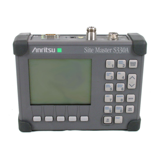
- Page 8 S i t e s t e r S 3 3 L IM D IS D IS Figure 1-1. Site Master System 1 - 0...
-
Page 9: General Information
Site Master Series instruments. This series has two mem- bers, as shown below. Throughout this manual, the term Site Master will refer to the series; whereas, the terms Site Master S330A, S331A will refer to the applicable individual models. -
Page 10: Standard Accessories
Chapter 1 General Information simultaneously charge the battery). Built-in energy conservation fea- tures can be used to extend battery life over an eight-hour work day. The Site Master is designed for measuring SWR, return loss, or cable insertion loss and locating faulty RF components in antenna systems. Power monitoring capability is available as an option. -
Page 11: Options
N type Standard Short, Part No. SM/STS • N type Standard Load, 35 dB, Part No. SM/STL • ANRITSU Precision N type Short/Open, Part No. 22N50 • Site Master Precision N Load, 42 dB, Part No. SM/PL • 7/16 (m) Precision Open/Short/Load, Part No. 2000-767 •... - Page 12 Chapter 1 General Information Adapter, 7/16 (f) to N (m), Part No. 510-90 • Adapter, 7/16 (f) to N (f), Part No. 510-91 • Adapter, 7/16 (m) to N (m), Part No. 510-92 • Adapter, 7/16 (m) to N (f), Part No. 510-93 •...
-
Page 13: Performance Specifications
Specifications are valid when the unit is calibrated at ambient tem- perature after a 5 minute warmup. Description Value Frequency Range: Site Master S330A 700 to 3300 MHz Site Master S331A 25 to 3300 MHz ° Frequency Accuracy (CW Mode) - Page 14 Chapter 1 General Information Table 1-1. Performance Specifications (2 of 2) Wattmeter Power Monitor: Range –50.0 to +20 dBm or 10.0 nW to 100.0 mW Offset Range 0 to +60.0 dB 0.1 dB or Resolution 0.1 xW Test Port, Type N 50 Ohms ***Immunity to Interfering signals up to the level of...
- Page 15 Chapter 1 General Information This page is intentionally blank 1 - 7...
- Page 16 External Power 12.5-15V DC Serial Interface Test Port Battery Charging Detector Input Back Lighting AUTO SCALE S i t e s t e r S 3 3 ESCAPE START CLEAR SAVE Up/Down A SETUP L I M RECALL SETUP MARKER Soft Keys LIMIT ENTER...
-
Page 17: Operation
Indicator light to show that the Site Master is being Power powered by the external charging unit. Serial Provides an RS232 DB9 interface with a Com Port Interface on a personal computer (for use with the ANRITSU Software Tools program). Also provides an interface 2 - 1... -
Page 18: Keypad
Chapter 2 Operation to a HP Deskjet 340 printer or a Seiko DPU-411 Thermal printer. Test Provides RF output, 50Wimpedance. Port RF Det Provides RF detector input for the Power Monitor. Keypad Turns the liquid crystal display (LCD) back-lighting ON or OFF. (Leaving back lighting off conserves battery power.) AUTO Automatically scales the display for optimum... - Page 19 Chapter 2 Operation ESCAPE/CLEAR key is held down, the factory pre- set state is restored. PRINT Prints the current display to the selected printer. RECALL Recalls a previously saved trace from memory loca- DISPLAY tion 1 through 40. When the key is pressed, “Recall display:”...
- Page 20 Chapter 2 Operation CAUTION:The selected memory location will be over- written by the SAVE DISPLAY operation. No warning is given. SAVE Saves the current system setup to 1 of 9 internal SETUP non-volatile memory locations. When the key is pressed, “Save Setup:” appears on the display. Select an appropriate number from the keypad and press the ENTER key to implement.
- Page 21 Chapter 2 Operation Connect SHORT, Press ENTER The Site Master then measures the calibration “short” that you must attach to the end of the test port or transmission line. Connect LOAD, Press ENTER The Site Master then measures the 50 ohm termina- tion (load) that you must attach to the end of the test port or transmission line.
-
Page 22: Soft Keys
Chapter 2 Operation AUTO SCALE ESCAPE CLEAR Display Area START RECALL SAVE SETUP SETUP Message Area LIMIT MARKER ENTER FREQ DIST SCALE POWER SAVE RECALL DISPLAY DISPLAY HOLD PRINT Soft Key Soft Keys Labels Figure 2-2. Site Master Front Panel Display Layout Soft Keys Each of the soft keys has a corresponding soft key label area on the dis- play. - Page 23 Chapter 2 Operation Figure 2-3. Site Master Menu Structure 2 - 7...
- Page 24 Chapter 2 Operation Main Menu At turn on, the Main Menu soft keys, below, are dis- played, and the Marker status is shown in the mes- sage area. DIST FREQ SCALE POWER These soft keys provide the following menu selec- tions: FREQ —...
- Page 25 Chapter 2 Operation Frequency Provides for setting sweep frequency end-points. Menu Also provides access to the Marker Menu. Selected (FREQ) frequency values may be changed using the keypad or Up/Down Arrow key. Choosing FREQ causes the soft keys, below, to be displayed and the corresponding values to be shown in the message area.
- Page 26 Chapter 2 Operation Markers Provides for setting marker values. Selected fre- Menu quency or distance values may be changed using the (MKRS) keypad or Up/Down Arrow key. Choosing MKRS causes the soft keys, below, to be displayed and the corresponding values to be shown in the message area.
- Page 27 Chapter 2 Operation Markers Provides for turning the selected marker on and off Menu and for setting marker values. Selected frequency and (2nd Level) distance values can be changed using the keypad or Up/Down Arrow key. Choosing M1, M2, M3, or M4 causes the soft keys, below, to be displayed and the corresponding values to be shown in the message area.
- Page 28 Chapter 2 Operation Markers Provides selections for placing the selected marker at Menu the frequency or distance with the maximum or mini- (3rd Level) mum SWR, RL or CL. Choosing MORE causes the soft keys, below, to be displayed and the corresponding values to be shown in the message area.
- Page 29 Chapter 2 Operation Distance Provides for setting Distance to Fault parameters. Se- Menu lected distance values may be changed using the key- (DIST) pad or Up/Down Arrow key. Entry can be in feet or meters, depending on the setting of the B5 soft key in the Option Sub-Menu (page 2-20).
- Page 30 Chapter 2 Operation NOTE: Refer to the table on the inside of the manual back cover for a listing of common coaxial cables showing values for “Relative Propagation Veloc- ity”and “Nominal Attenuation in dB/m @ 1000 MHz”. Distance Provides for setting the cable loss and relative propa- Sub-Menu gation velocity of the coaxial cable.
- Page 31 Chapter 2 Operation rapid means of setting both cable loss and propa- gation velocity. WINDW — Opens a menu of FFT windowing types for the DTF calculation. Use the Up/Down Arrow key and ENTER key to make a selection. NOTE: Using Windowing The theoretical requirement for inverse FFT is for the data to extend from zero frequency to infinity.
- Page 32 Chapter 2 Operation Distance To Fault Return Loss (dB) Feet Figure 2-4. Rectangular Windowing Example Distance To Fault Return Loss (dB) Feet Figure 2-5. Nominal Side Lobe Windowing Example 2 - 16...
- Page 33 Chapter 2 Operation Distance To Fault Return Loss (dB) Feet Figure 2-6. Low Side Lobe Windowing Example Distance To Fault Return Loss (dB) Feet Figure 2-7. Minimum Side Lobe Windowing Example 2 - 17...
- Page 34 Chapter 2 Operation Scale Menu Provides for changing the display scale. Selected val- (SCALE) ues may be changed using the keypad or Up/Down Arrow key. Choosing SCALE causes the soft keys, below, to be displayed and the corresponding values to be shown in the message area.
- Page 35 Chapter 2 Operation Option Provides for selecting Site Master options. Menu (OPT) Choosing OPT causes the soft keys, below, to be dis- played and the corresponding values to be shown in the message area. MORE B1 MODE — Opens a menu of measurement modes;...
- Page 36 Chapter 2 Operation MORE — Selects the Option Sub-Menu, de- scribed below. Option Provides for selecting additional Site Master options. Sub-Menu Choosing MORE causes the soft keys, below, to be displayed and the corresponding values to be shown in the message area. MAIN B5 UNITS —...
- Page 37 Chapter 2 Operation Power Provides for setting power monitor modes and pa- Menu rameters. Choosing POWER causes the soft keys, below, to be displayed and the corresponding values to be shown in the message area. UNITS OFFSET MAIN OFFSET ZERO UNITS —...
-
Page 38: Remote Operation
Chapter 2 Operation then subtracted from subsequent measurements prior to display. MAIN — Returns to the Main Menu. Remote Operation All Site Master functions, settings, and operating modes (except for power on/off) are controllable using commands sent from an external computer via the serial port. -
Page 39: Making Common Function Selections
Chapter 2 Operation Power monitor measurements can be either absolute or rela- • tive to some base power level, and can be displayed in either dBm or Watts. To allow measurement and display of power levels above the unit's specified input, the user may attenuate the signal and enter the corresponding offset. -
Page 40: Setting Options
Chapter 2 Operation Setting Options Step 3. Press the OPT soft key, from the Main Menu (page 2-8). Step 4. Accept or change the settings of the B1 through B8 options. Refer to pages 2-19 and 2-20 for a descrip- tion of each option. -
Page 41: Determining Remaining Battery Life
Chapter 2 Operation Determining Remaining Battery Life A symbol that denotes the charge state of the battery is continuously displayed in the top-right corner of the display (Figure 2-8). A totally black bar indicates a fully charged battery. Remaining Battery Life Sliding Gauge Symbol RETURN LOSS CAL A... -
Page 42: Making Frequency-Domain Measurements
Chapter 2 Operation Making Frequency-Domain Measurements Frequency domain measurements consist of Return Loss (RL), Stand- ing Wave Ratio (SWR), or Cable Loss (CL) measurements made over a selectable frequency range. Return Loss or SWR Measurement Selecting a Frequency Range Step 1. Press the FREQ soft key, from the Main Menu (page 2-8). - Page 43 Chapter 2 Operation “Connect LOAD, Press ENTER” instructions that appear in the message area. Connect the respective Open, Short, and Load component to the end of the Test Port Extension Cable (Figure 2-9) prior to press- ing ENTER. After each selection, one of the messages “Measur- ing OPEN,”...
-
Page 44: Making A Measurement
Thus, cables which are NOT phase stable may cause measurement errors that are more pronounced as the test frequency increases. For optimum calibration, ANRITSU recommends using precision calibration components. Making a Measurement Step 8. -
Page 45: Scaling The Display
Chapter 2 Operation Scaling the Display Step 10. The display can be scaled using either of the follow- ing methods: Automatically scale the display using the AUTO SCALE key (Figure 2-1, page 2-0). Manually scale the display using the SCALE soft key—from the Main Menu—and the TOP and BOTTOM soft keys from the ensuing soft key menu (page 2-18). -
Page 46: Adjusting A Limit
Chapter 2 Operation ing the keypad or the Up/Down Arrow key (Figure 2-1, page 2-0). Press ENTER when the data entry is complete. Step 15. Press the MAIN soft key to return to the Main Menu. Adjusting a Limit Step 16. Press the LIMIT key (Figure 2-1, page 2-0) to call up the Scale Menu. -
Page 47: Recalling A Setup
Chapter 2 Operation Recalling a Setup Step 22. Press the RECALL SETUP key. Step 23. Enter the desired numerical value using the keypad (1 to 9) or the Up/Down Arrow key. Press ENTER when data entry is complete. To restore the factory defaults, enter 0, then press ENTER. -
Page 48: Cable Loss Measurement
Chapter 2 Operation Cable Loss Measurement Selecting a Frequency Range Step 1. Press the FREQ soft key, from the Main Menu (page 2-8). Step 2. Press the F1 soft key from the Frequency Menu (page 2-9). Step 3. Enter the desired numerical value using the keypad or the Up/Down Arrow key (Figure 2-1, page 2-0). - Page 49 Open/ Short/Load calibration will cause uncompensated phase reflections inside the cable. Thus, cables which are NOT phase stable may cause measurement errors that are more pronounced as the test frequency increases. For optimum calibration, ANRITSU recommends using precision calibration components. 2 - 33...
-
Page 50: Making A Measurement
Chapter 2 Operation Making a Measurement Step 8. Connect the cable to be tested to the Site Master Test Port or the end of the Test Port Extension Cable (if used). Step 9. Place an Open or Short at the other end of the cable. Step 10. -
Page 51: Adjusting A Limit
Chapter 2 Operation 2-1, page 2-0). Press ENTER when the data entry is complete. Step 14. Press the BACK soft key to return to the Markers Menu. Step 15. Press the M2 soft key on the Markers Menu to select Marker 2. -
Page 52: Saving A Setup
Chapter 2 Operation Step 20. Press the B2 soft key from the Option Menu (page 2-19) to toggle the limit beep indicator ON. Saving a Setup Step 21. Press the SAVE SETUP key (Figure 2-1, page 2-0). Step 22. Enter the desired numerical value using the keypad (1 to 9) or the Up/Down Arrow key. -
Page 53: Making Distance-Domain Measurements
Chapter 2 Operation Making Distance-Domain Measurements Distance domain measurements—commonly known as distance-to- fault (DTF)—are made over a selectable distance range. They return in- formation that can help locate discontinuities in a transmission line. Selecting a Frequency Range NOTE: The maximum distance range is determined by the frequency span, number of data points, and relative propagation velocity: &... - Page 54 Chapter 2 Operation Figure 2-10. Maximum Distance and Resolution vs Frequency Span 2 - 38...
-
Page 55: Performing A Calibration
Chapter 2 Operation Step 5. Enter the desired numerical value using the keypad or the Up/Down Arrow key. Press ENTER when data entry is complete. Step 6. Check that the FREQ (MHz) scale in the display area indicates the new frequency start and stop values. Performing a Calibration Step 7. -
Page 56: Performing A Dtf Measurement
Thus, cables which are NOT phase stable may cause measurement errors that are more pronounced as the test frequency increases. For optimum calibration, ANRITSU recommends using precision calibration components. Performing a DTF Measurement Step 8. - Page 57 Chapter 2 Operation Step 12. Press the MKRS soft key to go to the Markers Menu (page 2-10). Step 13. Press the M1 soft key. Step 14. Press the ON/OFF soft key to turn M1 on, then press the EDIT soft key. Enter the desired numerical value using the keypad or the Up/Down Arrow key.
-
Page 58: Making Power Measurements
Chapter 2 Operation NOTES: Press the B5 soft key from the Option Sub-Menu (page 2-20) to toggle between feet and meters. Val- ues entered in either will freely convert to the other. Loss and relative propagation velocity values for many common cable types are listed in the table on the inside of the manual back cover. -
Page 59: Measuring High Input Power Levels
Chapter 2 Operation Measuring High Input Power Levels Step 3. Insert an attenuator between the DUT and the RF de- tector, sufficient to insure that the input power to the Site Master is no greater than 20 dBm. Step 4. Press the OFFSET soft key. -
Page 60: Printing
Chapter 2 Operation Printing Printing is accomplished with either of two printers: the Seiko DPU- 411 thermal printer or the Hewlett Packard DeskJet 340 ink jet printer. Figure 2-11 shows a setup diagram for these two printers. Printer Switch Settings Set the switches, SW1 and SW2, on the Seiko DPU-411 thermal printer as follows: Switch... -
Page 61: Printing A Screen
Chapter 2 Operation Printing a Screen Step 1. Connect the printer as shown in Figure 2-11. Step 2. Obtain a SWR, RL, CL, or Distance-to-Fault measurement display. Step 3. Select the printer using the B7 soft key from the Option Sub-Menu (page 2-20). Step 4. -
Page 62: Symbols
A listing of Range Error messages is given in Table 2-3. Replacing the Battery Replacing the battery is the only recommended field-level maintenance action. If your battery fails, contact your ANRITSU Sales Office or Service Center. Table 2-4 provides a listing of current service centers. 2 - 46... - Page 63 2-19). Lock fail indication. Check battery. (If Site Master fails to lock with a fully charged bat- tery, call your ANRITSU Service Center.) Processor timeout failure. Symbol appears at the frequency that causes an input RF overload; it then disappears as the sweep continues past that point.
- Page 64 Ambient temperature is not within the RANGE specified operating range. Return tempera- ture to specified operating range. If condi- tion persists, call your ANRITSU Service Center. Note: A listing of current ANRITSU service centers is given in Table 2-4. 2 - 48...
- Page 65 Chapter 2 Operation Table 2-4. Range Error Messages (1 of 2) Error Message Description RANGE The start (F1) frequency is greater than the ERROR:F1 > F2 stop (F2) frequency. RANGE The start (D1) distance is greater than the ERROR:D1 > D2 stop (D2) distance.
- Page 66 Chapter 2 Operation Table 2-3. Range Error Messages (2 of 2) Error Message Description DIST REQUIRES Valid distance to fault plots require a non- F1 < F2 zero frequency span. DIST REQUIRES Distance-to-fault measurements do not pro- vide usable data with CAL OFF. NO STORED Attempting to recall a display from a loca- SWEEP AT THIS...
-
Page 67: Using The Soft Carrying Case
Chapter 2 Operation Using the Soft Carrying Case The soft carrying case has been designed such that the strap can be un- snapped to allow the case to be easily oriented horizontally; thus allow- ing the Site Master controls to be more easily accessed (Figure 2-12). Figure 2-12. - Page 68 Chapter 2 Operation Table 2-4. ANRITSU Service Centers (1 of 2) UNITED STATES CHINA ANRITSU COMPANY ANRITSU BEIJING SERVICE CENTER 685 Jarvis Drive Beijing Fortune Building Morgan Hill, CA 95037-2809 416w, 5 Dong San Huan Bei Lu Telephone: (408) 776-8300...
- Page 69 Chapter 2 Operation Table 2-4. ANRITSU Service Centers (2 of 2) ISRAEL SOUTH AFRICA TECH-CENT, LTD ETESCSA Haarad St. No. 7, Ramat Haahayal 1st Floor Montrose Place Tel-Aviv 69701 Waterfall Park Telephone: (03) 64-78-563 Becker road FAX: (03) 64-78-334 MIDRAND...
-
Page 70: Software Tools Program
Chapter 3 Software Tools Program Description The Site Master Software Tools program provides the means for trans- ferring the measured trace, along with any applied markers and/or a limit, to the screen of an MS-DOS based personal computer (PC) run- ning Windows, Windows for Workgroups 3.xx, Windows NT, or Win- dows 95. -
Page 71: Communication Port Setting
Chapter 3 Screen Capture Program Communication Port Setting The Site Master Software Tools communicates with the Site Master through a standard COM port on the PC. It is important that your Win- dows COM port settings conform to the actual hardware settings. Table 3-1 provides a listing of standard COM port settings for most IBM AT-Compatible computers. - Page 72 Chapter 3 Screen Capture Program Figure 3-1. Windows 3.1 COM Port Setting Dialog Boxes Step 4. Change to the following settings if necessary: Baud Rate: 9600 Data Bits: Parity: None Stop Bits: Flow Control: None Step 5. Click on the Advanced... button. At the Advanced Settings dialog box verify the COM Port Base Ad- dress and IRQ.
-
Page 73: Changing Com Port Settings-Windows 95
Chapter 3 Screen Capture Program Note: If you changed the COM Port Base Address and/or IRQ, you will need to restart Windows. Figure 3-2. Windows 95 COM Port Setting Dialog Boxes Changing COM Port Settings–Wi ndows 95 Refer to Figure 3-2 while performing the following procedure. Step 1. - Page 74 Chapter 3 Screen Capture Program Step 4. Double click on the item Ports (COM & LPT) in the device list. Step 5. Double click on the Communications Port you want to set. The Communications Port Properties window appears. NOTE: If Windows doesn't show any available COM Ports, consult your computer manufacturer.
-
Page 75: Software Installation
For users new to Windows 3.x, a detailed procedure is given below. Step 1. Insert the ANRITSU Site Master Software Tools For Windows disk in floppy drive A:\ or B:\. Step 2. In the Windows Program Manager, pull down the File menu and select Run. -
Page 76: Plot Capture
Chapter 3 Screen Capture Program Step 7. Double-click on the “Site Master Help” icon to ac- quaint yourself with the comprehensive on-line man- ual. This manual provides descriptive narrative for the various program features and controls. Step 8. Double-click on the “Site Master Software Tools ” icon to open the Software Tools program. - Page 77 Chapter 3 Screen Capture Program Serial Interface Com port (Program defaults to Com2) Figure 3-3. Equipment Setup for Site Master Tools Operation Step 4. Click on Capture, in the top menu bar, and select Capture Multiple Traces from the drop-down menu.
-
Page 78: Single Trace Capture
Chapter 3 Screen Capture Program Single trace capture Step 1. Perform steps 1, 2, and 3 of the multiple-trace- capture procedure. Step 2. Click on Capture, in the top menu bar, and select Start Capture from the drop-down menu. Step 3. Observe that a “Waiting for Data”... -
Page 79: Program Operation
Chapter 3 Screen Capture Program Click on Default Plot Settings, pull down menu. Click on Per Site Master, in the dialog box, and select OK to save changes. On the Site Master, press the ENTER key to re- send the plot. Program Operation The captured trace on the PC can be scaled and have its limit line, markers, and properties changed. -
Page 80: Fault Location Software
Chapter 3 Screen Capture Program Fault Location Software A captured RL or SWR trace can be transformed to a Distance to Fault display. This is useful for determining the location of faults, connec- tions, and other discontinuities within the cable. To transform a plot, select Fault Find from the Tools menu (or click the toolbar button). -
Page 81: Saving A Plot As A Windows Metafile
Chapter 3 Screen Capture Program Saving a Plot as a Wi n dows Me - tafile Plots can be saved as Windows Metafiles (.WMF). The metafile may be imported into other graphic programs, but cannot be reloaded into the Site Master Software Tools program. To save a plot as a Windows Metafile, click on File, in the top menu bar, and select Save as Metafile from the drop down menu. -
Page 82: Drag-N-Drop
Chapter 3 Screen Capture Program “Drag-n-Drop” Site Master Software Tools is Windows based. Graphs can “Drag-n- Drop” onto each other. Site Master Software Tools allows quick com- parison of “before” and “after” Distance-To-Fault measurements. Re- cent data is compared to a historical PC database record, which is usually recorded during site installation/commissioning. - Page 83 Chapter 3 Screen Capture Program NOTES 3-14...
- Page 84 Coaxial Cable Technical Data Relative Propagation Nominal Attenuation Cable Type Velocity ( dB/m @ 1000 MHz RG8, 8A,10,10A 0.659 0.262 RG9, 9A 0.659 0.289 RG17, 17A 0.659 0.180 RG55,55A, 55B 0.659 0.541 RG58, 58B 0.659 0.558 RG58A, 58C 0.659 0.787 RG142 0.659 0.443...
- Page 85 Color Cover P/N 00986-00018...
Need help?
Do you have a question about the Site Master S330A and is the answer not in the manual?
Questions and answers