
Related Manuals for Anritsu 681XXC


Summary of Contents for Anritsu 681XXC
-
Page 1: Operation Manual
SERIES 681XXC SYNTHESIZED SIGNAL GENERATOR OPERATION MANUAL 490 JARVIS DRIVE P/N: 10370-10333 MORGAN HILL, CA 95037-2809 REVISION: B PRINTED: APRIL 2001 COPYRIGHT 1999 ANRITSU CO. - Page 2 WARRANTY The Anritsu product(s) listed on the title page is (are) warranted against defects in materials and workmanship for one year from the date of shipment. Anritsu’s obligation covers repairing or replacing products which prove to be defective during the warranty period.
-
Page 4: Safety Symbols
To prevent the risk of personal injury or loss related to equipment malfunction, Anritsu Company uses the following symbols to indicate safety-related information. For your own safety, please read the information carefully BEFORE operating the equipment. WARNING CAUTION 681XXC OM Safety Symbols WARNING indicates a hazard. - Page 5 There is a risk of back injury, if this equipment is lifted by one person. WARNING If the equipment is used in a manner not specified by the manufacturer, the protection provided by the equipment may be impaired. 681XXC OM...
-
Page 6: Table Of Contents
Preliminary ....2-10 Procedure ....2-10 681XXC OM... - Page 7 INSTRUMENT START-UP ... . . 3-14 Powering Up the 681XXC ... . 3-14 Start-Up Display ....3-14 Standby Operation .
- Page 8 Self Test ..... 5-4 Resetting the 681XXC ....5-4 Warmup Time .
- Page 9 Connecting the 681XXC to the HP8757D ..7-16 Setting Up the 681XXC ... . . 7-17 Initiating HP8757D SNA Operation ..7-19...
- Page 10 INTRODUCTION ....A-1 REAR PANEL CONNECTORS ... A-1 CONNECTOR PINOUT DIAGRAMS ..A-1 Appendix B Performance Specifications 681XXC OM v/vi...
- Page 11 Table of Contents (Continued)
- Page 12 Table of Contents SCOPE OF MANUAL ....1-3 INTRODUCTION ....1-3 DESCRIPTION .
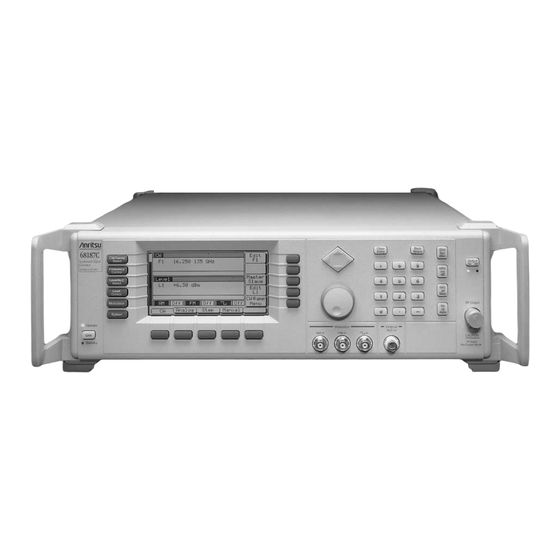
- Page 13 Figure 1-1. Series 681XXC Synthesized Signal Generator...
-
Page 14: Scope Of Manual
This manual provides general information, installation, and operating information for the Anritsu Series 681XXC Synthesized Signal Gen- erator. (Throughout this manual, the terms 681XXC and signal gen- erator will be used interchangeably to refer to the instrument.) Man- ual organization is shown in the table of contents. - Page 15 GENERAL INFORMATION Table 1-1. Series 681XXC Models 681XXC Frequency Model 68117C 0.01 – 8.4 GHz 68137C 2.0 – 20.0 GHz 68147C 0.01 – 20.0 GHz 0.01 – 2.0 GHz 68167C 2.0 – 20.0 GHz 20.0 – 40.0 GHz 0.01 – 2.0 GHz 2.0 –...
-
Page 16: Identification Number
ELECTRONIC MANUAL RELATED MANUALS 681XXC OM All Anritsu instruments are assigned a unique six-digit ID number, such as “875012”. The ID number is imprinted on a decal that is af- fixed to the rear panel of the unit. Special-order instrument configura- tions also have an additional special serial number tag attached to the rear panel of the unit. -
Page 17: Maintenance Manual
OPTIONS Maintenance The Maintenance Manual supplies service informa- Manual tion for all models in the 681XXC series. The service information includes functional circuit descriptions, block diagrams, performance verification tests, cali- bration procedures, troubleshooting data, and as- sembly and component removal/replacement procedures. -
Page 18: Performance Specifications
£20 GHz, rated output power is reduced by 1 dB; in models having a high-end frequency of >20 GHz, rated output power is reduced by 2 dB. Series 681XXC Synthesized Signal Generator performance specifica- tions are provided in Appendix B. PERFORMANCE SPECIFICATIONS /day frequency stability. -
Page 19: Recommended Test Equipment
GENERAL INFORMATION RECOMMENDED TEST EQUIPMENT Table 1-2 lists the recommended test equipment for performing the Se- ries 681XXC Synthesized Signal Generator operation verification tests in Chapter 5. Table 1-2. Recommended Test Equipment Instrument Critical Specification Frequency Range: 0.01 to 65 GHz... - Page 20 Table of Contents INTRODUCTION ....2-3 INITIAL INSPECTION ....2-3 PREPARATION FOR USE .
-
Page 22: Introduction
Anritsu Customer Service. If either the shipping container is damaged or the cushioning material shows signs of stress, notify the carrier as well as Anritsu. Keep the shipping materials for the carrier’s inspec- tion. -
Page 23: Preparation For Use
(Figure 2-1). When the switch is set to 110 Vac, the 681XXC accepts 90 to 132 Vac line voltage. When the switch is set to 220 Vac, the 681XXC accepts 180 to 264 Vac line voltage. If the selector setting is in- correct for the line voltage available, change it to the correct setting. -
Page 24: Standby Operation
This keeps the internal timebase frequency reference at operating temperature. On the front panel, press LINE to switch the 681XXC from OPERATE (green LED on) to STANDBY (orange LED on). During standby operation, the fan runs continuously. -
Page 25: Warmup Time
Instruments disconnected from AC power for more than 72 hours require 30 days to return to specified aging. Operating The 681XXC can be operated within the following Environment environmental limits. Temperature. 0°C to 50°C. Humidity. 5 to 95% relative at 40°C. -
Page 26: Gpib Setup And Interconnection
INSTALLATION GPIB SETUP AND INTERCONNECTION 681XXC OM The 681XXC provides automated microwave signal generation via the GPIB. The following paragraphs provide information about interface connections, cable requirements, setting the GPIB operating parame- ters, and selecting the external interface language. Interface... - Page 27 Enter a new address using the cursor control key or the data entry keypad and the terminator key ADRS The new GPIB address will now appear on the dis- play. The entry must be between 1 and 30 to be rec- ognized as a valid GPIB address. 681XXC OM...
-
Page 28: Selecting The Line Terminator
Language external interface languages—Native or SCPI (Op- tion 19). The Native interface language uses a set of 681XXC GPIB Product Specific commands to control the instrument; the SCPI interface language uses a set of the Standard Commands for Programmable Instruments commands to control the unit. -
Page 29: Rack Mounting Kit Installation
Figure 2-2. Front Handle, Feet, and Carrying Handle Removal RACK MOUNTING KIT INSTALLATION 681XXC OM... - Page 30 The screws with green heads have metric threads. When it becomes necessary to replace any of these screws, always use the exact re- placement green-headed screws (Anritsu P/N 2000-560) to avoid damage to the instrument. 681XXC OM Step 4 Remove the inner slide assemblies from the outer slide assemblies.
- Page 31 WARNING Use two or more people to lift and move this equipment, or use an equipment cart. There is a risk of back injury, if this equipment is lifted by one person. RACK MOUNTING KIT INSTALLATION 681XXC OM...
-
Page 32: Preparation For Storage/Shipment
INSTALLATION PREPARATION FOR STORAGE/SHIPMENT 681XXC OM The following paragraphs give instructions for preparing the 681XXC for storage or shipment. Preparation Preparing the signal generator for storage consists for Storage of cleaning the unit, packing the inside with mois- ture-absorbing desiccant crystals, and storing the unit in a temperature environment that is main- tained between –40°C and +75°C. - Page 33 INSTALLATION Table 2-1. ANRITSU Service Centers UNITED STATES ANRITSU COMPANY 490 Jarvis Drive Morgan Hill, CA 95037-2809 Telephone: (408) 776-8300 1-800-ANRITSU FAX: 408-776-1744 ANRITSU COMPANY 10 New Maple Ave., Unit 305 Pine Brook, NJ 07058 Telephone: (201) 227-8999, 1-800-ANRITSU FAX: 201-575-0092 ANRITSU COMPANY 1155 E.
- Page 34 INSTRUMENT START-UP ... . . 3-14 Powering Up the 681XXC ... . 3-14 Start-Up Display ....3-14 Standby Operation .
- Page 35 Selecting a CW Power Sweep Trigger ..3-55 Selecting a Power Level Sweep Range..3-56 Selecting a Sweep Frequency/Step Power Mode . 3-58 Setting Power Level Step Size ..3-59 681XXC OM...
- Page 36 Erasing Stored Setups ... . . 3-90 3-15 SECURE OPERATION ....3-91 3-16 REFERENCE OSCILLATOR CALIBRATION . . . 3-92 681XXC OM...
-
Page 38: Introduction
Chapter 3 Local (Front Panel) Operation This chapter provides information and instructions on operating the Series 681XXC Synthesized Signal Generator using the front panel controls. It contains the following: Illustrations and diagrams of the front panel, data display area, and data entry area that identify and describe all front panel controls, inputs, and outputs. -
Page 39: Front Panel Layout
FRONT PANEL LAYOUT Figure 3-1. Front Panel, 681XXC Synthesized Signal Generator The 681XXC front panel is divided into two main areas—the data dis- play area and the data entry area. The following paragraphs provide a brief description of the front panel controls, inputs, outputs, and data display and data entry areas as shown in Figure 3-1. -
Page 40: Rf Output Control Key
Data Entry The data entry area consists of data entry keys and Area controls that provide for (1) changing values for each 681XXC parameter, and (2) terminating the value entry and assigning the appropriate units (GHz, MHz, dBm, etc.). RF Output The RF output control key provides for turning the RF output power on and off. -
Page 41: Data Display Area
The paragraphs that follow provide descriptions of the menu display elements and the menu keys. Frequency Level Mode Mode Parameters Area Title Bar Menu Soft-Keys DATA DISPLAY AREA Level Menu Menu Parameters Labels Area Side Keys Soft-Keys Menu Labels Bottom Keys 681XXC OM... -
Page 42: Menu Display Format
LOCAL (FRONT PANEL) OPERATION 681XXC OM Menu Display The menu display is divided into specific areas that Format show the frequency, power level, and modulation in- formation for the current signal generator setup. Menu labels for the current menu’s soft-keys appear along the bottom and right side of the display. -
Page 43: Menu Keys
ALC, ALC/attenuator decou- pling, ALC slope, and user level flatness cor- rection). LEVEL CONTROL—In Level mode, this menu lets you select the level parameter (L0- L9) to use for a CW frequency or a frequency DATA DISPLAY AREA 681XXC OM... - Page 44 LEVEL/ALC SELECT LEVEL CONTROL MODULATION SYSTEM 681XXC OM DATA DISPLAY sweep. In the Level Sweep mode, this menu lets you select the power sweep range parame- ters to use. MODULATION—This menu provides you with access to sub-menus that let you select...
-
Page 45: Panel Operation
Figure 3-3. Front Panel Data Entry Area 3-12 The value of a selected 681XXC parameter can be changed using the rotary data knob and/or keys of the data entry area. Each element of the data entry area is identified in Figure 3-3 and described in the fol- lowing paragraphs. - Page 46 GHz / Sec / dBm for V MHz / ms / dB for mV kHz / ms / STEPS for mV 681XXC OM Rotary Data Knob The rotary data knob can be used to change the value of a parameter that is open for editing. The cursor is moved under the open parameter using the <...
-
Page 47: Instrument Start-Up
Begin by powering it up. Powering Up Connect the 681XXC to an ac power source by fol- the 681XXC lowing the procedure in the Installation chapter. -
Page 48: Self-Testing The 681Xxc
System Menu (below) is displayed, press Selftest . Resetting to You can reset the 681XXC to the factory-selected default parameter values at any time during normal Default operation. The default parameters are shown in Parameters Table 3-1 on the following page. -
Page 49: Reset (Default) Parameters
–2.0 –3.0 –4.0 –1.0 –2.0 –3.0 –4.0 RESET (DEFAULT) PARAMETERS –5.0 –6.0 –7.0 –8.0 –5.0 –6.0 –7.0 –8.0 –5.0 –6.0 –7.0 –8.0 –5.0 –6.0 –7.0 –8.0 –5.0 –6.0 –7.0 –8.0 –5.0 –6.0 –7.0 –8.0 –5.0 –6.0 –7.0 –8.0 681XXC OM... - Page 50 50 ms 68147C 50 ms 68167C 50 ms 68177C 50 ms 68187C 50 ms 68197C 50 ms 681XXC OM STEP SWEEP NUMBER OF DWELL TIME STEPS 1 ms 1 ms 1 ms 1 ms 1 ms 1 ms 1 ms...
-
Page 51: Entering Data
At this menu display, you can edit both the CW fre- quency and the output power level parameters. If you wish to follow along on your 681XXC, you can obtain this same menu display by resetting your instrument (press press Reset ). -
Page 52: Editing The Current Value
PANEL) OPERATION Cursor Control Rotary Data Knob 681XXC OM Editing the To change the current value of a parameter by edit- Current Value ing, you can use either the cursor control key or the rotary data knob. Using the Cursor Control Key Using the <... -
Page 53: Entering A New Value
Now, try entering a new value for the CW frequency displayed on your synthesizer using the data entry keypad and termination keys. To close the open parameter when you are finished entering data, press Edit F1 or make another menu selection. ENTERING DATA NOTE 681XXC OM... -
Page 54: Cw Frequency Operation
One of the signal generator’s major functions is to produce discrete CW frequencies across the frequency range of the instrument. The following paragraphs describe how to place the 681XXC in the CW frequency mode, select a CW frequency and power level for output, and activate the CW ramp. -
Page 55: Selecting A Cw Frequency
Select preset frequencies F0, F1, F2, M1, or M2 for output. Go to the frequency list menu (to tag, edit,or output a frequency from the list). Go to the tagged frequencies menu (select a tagged frequency for output). CW FREQUENCY OPERATION FREQUENCY CONTROL 681XXC OM... - Page 56 LOCAL (FRONT PANEL) OPERATION 681XXC OM CW FREQUENCY Frequency List–To go to the Frequency List Menu (below), press Freqs List . This menu lets you tag, edit, or output a frequency from the list. Use the cursor control key to select a frequency from the frequency list.
-
Page 57: Selecting A Power Level
You can also select any of the preset power levels or a power level sweep for a CW frequency. For instructions, refer to paragraphs 3-9 (Fixed Power Level Op- eration) and 3-10 (Power Level Sweep Operation). CW FREQUENCY OPERATION NOTE 681XXC OM... -
Page 58: Cw Ramp
LOCAL (FRONT PANEL) OPERATION 681XXC OM CW Ramp When active, the signal generator’s CW ramp pro- vides a repetitive 0V to 10V ramp output to the rear panel HORIZ OUT BNC connector and AUX I/O con- nector. The CW ramp is used to drive a scalar ana- lyzer display. -
Page 59: Analog Sweep Mode
3-26 The signal generator can generate broad (full range) and narrow band sweeps across the frequency range of the instrument. The 681XXC has four sweep frequency modes—analog sweep, step sweep, manual sweep, and list sweep. Descriptions and operating instructions for the analog, step, and manual sweep frequency modes begin on this page. - Page 60 LOCAL (FRONT PANEL) OPERATION 681XXC OM This menu lets you perform the following: Select a sweep range (edit the sweep start and stop frequency parameters). Go to the sweep ramp menu (set the sweep time and select a sweep trigger).
-
Page 61: Selecting A Sweep Trigger
If you select the single sweep trigger mode, the menu display adds the menu soft-key Trig . Press- ing Trig starts a single sweep. If a single sweep is in progress, pressing Trig causes the sweep to abort and reset. SWEEP FREQUENCY OPERATION 681XXC OM... -
Page 62: Step Sweep Mode
(linear or logarithmic) and sweep trigger are controllable from step sweep menus. Selecting To place the 681XXC in step sweep frequency mode, Step Sweep press the main menu key Mode At the resulting menu display, press Step . The Step Sweep Menu (below) is then displayed. - Page 63 Press Dwell Time to open the dwell time-per-step parameter. Press Step Size to open the step size parameter. Press Num of Steps to open the number of steps parameter. OPERATION 681XXC OM...
- Page 64 LOCAL (FRONT PANEL) OPERATION 681XXC OM SWEEP FREQUENCY Open the parameter you wish to change, then edit the current value using the cursor control key or the rotary data knob or enter a new value using the key pad and appropriate termination key. When you...
-
Page 65: Manual Sweep Mode
1 kHz (0.1 Hz with Option 11) to the full frequency range of the instrument; the number of steps range is 1 to 10,000. Selecting To place the 681XXC in manual sweep frequency Manual mode, press the main menu key Sweep Mode At the resulting menu display, press Manual . -
Page 66: Selecting A Sweep Range
(1) the analog sweep start fre- quency entered is greater than the stop frequency, or (2) the dF value entered results in a sweep outside the range of the 681XXC. Entering valid values will clear the error. 681XXC OM Selecting a... - Page 67 Select the frequency parameters for each pre- set sweep range. Select an output power level for the sweep. Go to the marker list menu (analog and step sweep frequency modes only). OPERATION 681XXC OM...
-
Page 68: Selecting A Power Level
LOCAL (FRONT PANEL) OPERATION 681XXC OM Setting a Preset Sweep Range–At the menu, se- lect the sweep range (F1-F2, F3-F4, F5-dF, or F6-dF) that you wish to set. The menu then displays the current frequency parameters for the selected sweep range. -
Page 69: Frequency Markers
Marker frequency accuracy is the same as sweep frequency accuracy. The markers are visible on a CRT display. The 681XXC generates two types of markers. Video Marker–produces a pulse on a CRT display at each marker frequency. The video marker is either a +5V or a –5V pulse at the... - Page 70 LOCAL (FRONT PANEL) OPERATION 681XXC OM SWEEP FREQUENCY Use the cursor control key to select a frequency parameter from the marker list. The selected fre- quency parameter is highlighted in reverse video and displayed in full below the marker list.
-
Page 71: Selecting Alternate Sweep Mode
Press Alt Sweep to turn on the alternate sweep mode. Notice that the Alternate Sweep menu (on the following page) changes to show that the alter- nate sweep is now active. SWEEP FREQUENCY OPERATION 681XXC OM... - Page 72 LOCAL (FRONT PANEL) OPERATION 681XXC OM SWEEP FREQUENCY Now, press Previous Menu to return to the Step Sweep Menu display (or the Analog Sweep Menu display if operating in analog sweep frequency mode). Notice the changes to the Step Sweep Menu display (below).
- Page 73 When you are done selecting the power level for the alternate sweep range and editing the power level of the main sweep, press Previous Menu to return to the Alternate Sweep Menu display. SWEEP FREQUENCY OPERATION 681XXC OM...
-
Page 74: List Sweep Mode
LOCAL (FRONT PANEL) OPERATION 681XXC OM List Sweep In list sweep frequency mode, the output is a step Mode sweep of up to 2000 phase-locked, non-sequential frequencies. Each frequency can have a different power level setting. The list index (0 thru 1999) identifies each frequency/power level set in the list. -
Page 75: Selecting List Sweep Mode
LOCAL (FRONT PANEL) OPERATION 3-42 Selecting List To place the 681XXC in list sweep frequency mode, Sweep Mode press the main menu key At the reulting menu display, press List . The List Sweep Menu (below) is displayed. This menu lets you perform the following:... -
Page 76: Editing The List
LOCAL (FRONT PANEL) OPERATION 681XXC OM Performing List Calculations The PreCalc List soft-key initiates a process that examines every index in the list and performs all the calculations necessary to set the frequency and power levels. The soft-key does not have to be pressed every time the list changes. - Page 77 The menu displays a total of 10 power levels. Use the cursor control key to select a power level from the list. The selected power level is highlighted in reverse video and displayed in full below the power level list. OPERATION 681XXC OM...
- Page 78 LOCAL (FRONT PANEL) OPERATION 681XXC OM SWEEP FREQUENCY Press Edit to edit the highlighted power level or en- ter a new power level. Press Page Up to scroll the displayed power levels to the next 10 in the list. Press Page Down to scroll the displayed power levels to the previous 10 in the list.
-
Page 79: Selecting A List Sweep Range
To go to the Sweep Menu (below) from the main List Sweep menu, press Sweep Menu . This menu lets you select a list sweep range, set the dwell-time-per-step, and go to the trigger menu. SWEEP FREQUENCY OPERATION 681XXC OM... -
Page 80: Selecting A List Sweep Trigger
LOCAL (FRONT PANEL) OPERATION 681XXC OM Press Start Index to open the list sweep start index parameter. Press Stop Index to open the list sweep stop index parameter. Press Dwell Time to open the dwell-time-per-step parameter. Open the parameter you wish to change, then edit... - Page 81 Auto trigger is automatically turned off and Manual trigger is selected. Thus, when list sweep mode is entered, the display updating will be back to nor- mal speed. OPERATION 681XXC OM...
-
Page 82: Fixed Power Level Operation
Fixed (Non-Swept) Power Level Mode menu map (Chapter 4, Fig- ure 4-7) to follow the menu sequences. Selecting To place the 681XXC in a fixed power level mode Fixed Power from a CW or sweep (analog, step, or manual) fre-... - Page 83 (in reverse video) to reflect your selection. Level List– To go to the Level List menu (below), press Level List . This menu lets you select a power level from the list to tag, edit, or output. 681XXC OM...
- Page 84 LOCAL (FRONT PANEL) OPERATION 681XXC OM FIXED POWER LEVEL OPERATION Use the cursor control key to select a power level from the level list. The selected power level is high- lighted in reverse video and displayed in full below the level list.
-
Page 85: Level Offset
681XXC RF output and the test device. Using the level offset function, you can apply a constant to the displayed power level that compensates for this loss or gain. -
Page 86: Power Level Sweep Operation
(linear or logarithmic) and sweep trigger. To place the 681XXC in a CW power sweep mode from a CW frequency menu, press the main menu At the resulting menu display, press Lvl Swp . The CW Level Sweep Menu (below) is displayed. -
Page 87: Dwell Time
To go to the CW Level Sweep Trigger menu from this menu, press Trigger Menu . The trigger menu is described on the following page. Press Previous Menu to return to the CW Level Sweep Menu display. POWER LEVEL SWEEP OPERATION 681XXC OM... -
Page 88: Selecting A Cw Power Sweep Trigger
LOCAL (FRONT PANEL) OPERATION 681XXC OM Selecting a There are three modes of triggering provided for the CW Power CW power sweep—automatic, external, and single. Sweep The sweep trigger is selectable from the CW Level Trigger Sweep Trigger menu. The following is a description of each trigger mode. -
Page 89: Selecting A Power Level Sweep Range
(press Edit L1 or Edit L2 ). Enter a new power level using the keypad and ap- propriate terminator key. When you are finished, close the open parameter by pressing its menu edit soft-key or by making another menu selection. POWER LEVEL SWEEP OPERATION 681XXC OM... - Page 90 LOCAL (FRONT PANEL) OPERATION 681XXC OM POWER LEVEL SWEEP OPERATION Selecting a Preset Power Level Sweep Range There are five preset power level sweep range pa- rameters selectable in the power level sweep modes. These preset power level sweep range parameters are L1-L2, L3-L4, L5-L6, L7-L8, and L9-L0.
-
Page 91: Selecting A Sweep Frequency/Step Power Mode
Go to the sweep ramp menu (set the step size or number of steps). To select logarithmic or linear power level sweep or to select a power level sweep range, refer to the procedures on pages 3-56 and 3-57. POWER LEVEL SWEEP OPERATION LEVEL/ALC SELECT NOTE 681XXC OM... -
Page 92: Setting Power Level Step Size
0.01 dB (Log) or 0.001 mV (Linear). Entering a valid step size will clear the error. 681XXC OM Setting Power There are two ways to set the step size of the power Level Step... -
Page 93: Leveling Operations
LEVELING OPERATIONS 3-60 The 681XXC generates leveled output power over a maximum range of up to 33 dB (up to 149 dB with Option 2). Instruments with Option 15A provide leveled output power over a maximum range of up to 27 dB (up to 141 dB with Option 2). - Page 94 This is the normal (default) leveling mode. Output power is sensed by the internal detector in the 681XXC. The detector output signal is fed back to the ALC circuitry to adjust the output power level. Internal ALC is selected from the leveling menu.
- Page 95 Ext ALC Adj , then use the cursor control key or rotary data knob to adjust the external ALC signal to obtain the set power level. To return to the Leveling Menu, press ALC Mode then press Leveling Menu . LEVELING OPERATIONS 681XXC OM...
- Page 96 LOCAL (FRONT PANEL) OPERATION 681XXC OM OPERATIONS At the Leveling menu, pressing either Internal or Fixed Gain will turn off external leveling. Press Previous Menu to return to the ALC Mode Menu display. Fixed Gain In the fixed gain mode, the ALC is disabled. The RF Level DAC and step attenuator (if installed) are used to control the relative power level.
-
Page 97: Attenuator Decoupling
Edit L1 to close the open parameter. To change the attenuation setting, press Incr Atten or Decr Attn . Pressing these soft-keys changes the attenuation in 10 dB steps. Press Previous Menu to return to the ALC Mode Menu display. LEVELING OPERATIONS 681XXC OM... -
Page 98: Alc Power Slope
LOCAL (FRONT PANEL) OPERATION 681XXC OM ALC Power The ALC power slope function lets you compensate Slope for system, cable, and waveguide variations due to changes in frequency, by linearly increasing or de- creasing power output as the frequency increases. - Page 99 Edit Slope again or by making another menu selection. While monitoring the power level at the device- under-test (DUT), adjust the power slope and pivot point to level the power at the DUT. LEVELING OPERATIONS 681XXC OM...
-
Page 100: User Cal (User Level Flatness Correction)
Up to five user level flatness correction power-offset tables from 2 to 801 frequency points/table can be created and stored in 681XXC memory for recall. The GPIB power meters supported are the Anritsu Models ML2437A, ML2438A, and ML4803A and the Hewlett-Packard Models 437B, 438A, and 70100A. - Page 101 Power Meter Model and GPIB Address In order for the 681XXC to control the power meter, the GPIB address and power meter model must be selected from the Configure GPIB menu.
- Page 102 At the Configure GPIB menu, press Previous Menu to return to the System Configuration Menu display. Creating a Power-Offset Table The 681XXC must be in CW frequency mode and fixed (non-swept) power level mode in order to cre- ate a power-offset table for user level flatness cor- rection.
- Page 103 LEVEL/ALC SELECT At the resulting menu display, press Level . The 681XXC is now in fixed (non-swept) power level mode. At the Level Menu, press User Cal . The User Level Cal Menu (below) is displayed.
- Page 104 User level flatness correction can be applied to the test setup using a power-offset table created from calculated data and entered via the GPIB. Refer to the 681XXC Programming Manual (P/N 10370- 10334) for information and instructions on creating a power-offset table and entering it via the GPIB.
- Page 105 To perform a master reset, proceed as follows: Step 1 With the 681XXC in standby, press and hold the RF OUTPUT ON/OFF key. Step 2 Press the LINE OPERATE/STANDBY key to turn the instrument on.
-
Page 106: Signal Modulation
To provide amplitude modulation, first set up the Amplitude external signal generator, then connect it to either Modulation the 681XXC front or rear panel AM IN connector. Next, press MODULATION display, press AM . The right-most External AM Status Menu (below) is displayed. Pressing “More”... -
Page 107: Frequency Modulation Operating Modes
In Unlocked Narrow mode, frequency modulation is obtained by applying the modulating signal to the fine tuning coil of the YIG-tuned oscillator. Un- locked Narrow FM mode allows maximum devia- tions of ±10 MHz for DC to 500 kHz rates. SIGNAL MODULATION 681XXC OM... -
Page 108: Providing Frequency Modulation
To provide frequency modulation, first set up the ex- Frequency ternal signal generator, then connect it to either the Modulation 681XXC front or rear panel FM IN connector. Next, press MODULATION display, press FM . The right-most External FM Status Menu (below) is displayed. Pressing More brings up the left-most menu. - Page 109 Press 600W/50W to select the input impedance of the input connector. The FM status display will reflect your selection. Press Front/Rear to select the front or rear panel FM IN connector. The FM status display will reflect your selection. SIGNAL 681XXC OM...
-
Page 110: Square Wave Modulation Operating Modes
400 Hz, 1 kHz, 7.8125 kHz, and 27.8 kHz. The modulating signals are selectable from a menu. The 681XXC accepts modulating signals from an ex- ternal signal generator that are TTL-compatible with the minimum pulse width of >5 ms. - Page 111 Use the cursor control key to chose the desired modulating signal frequency, then press Select to enter the selection into memory. The Square Wave status display will reflect your selection. Press Previous Menu to return to the initial Square Wave Status Menu display. SIGNAL 681XXC OM...
- Page 112 LOCAL (FRONT PANEL) OPERATION 681XXC OM MODULATION External Source Input Connector Selection If you have selected External to use a modulating signal from an external source, then when you press More the menu (below) is displayed. Press Front/Rear to select the front or rear panel IN connector.
-
Page 113: System Configuration
To go to the System Configuration menu, first press System Menu display, press Config . The System Configuration Menu (below) is displayed. This menu lets you go to the Front Panel, Rear Panel, RF, GPIB, and Increment Configuration menus. SYSTEM CONFIGURATION SYSTEM . At the 681XXC OM... -
Page 114: Configuring The Front Panel
LOCAL (FRONT PANEL) OPERATION 681XXC OM Configuring Configuring the front panel of the signal generator the Front involves adjusting the intensity level of the data dis- Panel play for ease of viewing. To go to the Configure Front Panel menu from the System Configuration menu, press Front Panel . -
Page 115: Configuring The Rear Panel
ON. The video marker signal output is avail- able at the rear panel AUX I/O connector. The display will reflect your selection. Press Previous Menu to return to the System Con- figuration Menu display. SYSTEM CONFIGURATION 681XXC OM... -
Page 116: Configuring The Rf
LOCAL (FRONT PANEL) OPERATION 681XXC OM Configuring Configuring the RF of the 681XXC involves the fol- the RF lowing: Selecting whether the RF should be on or off during retrace. Selecting whether the RF should be on or off during frequency switching in CW, step sweep, and list sweep modes. - Page 117 For example: Frequency scaling set to 4 CW frequency set to 20 GHz 681XXC output frequency is 5 GHz (20 GHz ¸ 4) Press Freq Scaling to open the reference multiplier parameter, then edit the current value using the cursor control key or rotary data knob or enter a new value using the data entry key pad and any ter- minator key.
-
Page 118: Configuring The Gpib
GPIB Menu (below) is displayed. Press GPIB Address to change the address of the 681XXC on the bus (the signal generator’s default GPIB address is 5). Enter a new address, between 1 and 30, using the cursor control key or the data en- try keypad and the terminator key The new GPIB address will appear on the display. - Page 119 Anritsu Model 360B Vector Network Analyzer. (Refer to paragraph 7-4 for information pertaining to operating the 681XXC with a 360B VNA.) Press SS Mode again to turn the source lock mode off. Press More to go to the First Additional Configure GPIB menu for more selections.
- Page 120 CONFIGURATION Press Native SCPI to select the external interface language to be used for remote operation of the 681XXC. (Language selection is only available on instruments that have Option 19 installed.) Press More to go to the Second Additional Config- ure GPIB menu.
-
Page 121: Setting Increment Sizes
Press Incr Mode to turn the increment mode on. Press again to turn it off. When done, press Previous Menu to return to the System Configuration Menu display. SYSTEM CONFIGURATION 681XXC OM... -
Page 122: Saving/Recalling Instrument Setups
3-14 SAVING/RECALLING INSTRUMENT SETUPS 681XXC OM The 681XXC offers the capability to store up to ten complete front panel setups. The setups are numbered 0 through 9. The following paragraphs describe how to save and recall front panel setups. Saving... -
Page 123: Erasing Stored Setups
To perform a master reset, proceed as follows: Step 1 With the 681XXC in standby, press and hold the RF OUTPUT ON/OFF key. Step 2 Press the LINE OPERATE/STANDBY key to turn the instrument on. -
Page 124: Secure Operation
3-15 SECURE OPERATION 681XXC OM The 681XXC can be operated in a secure mode of operation. In this secure mode, the display of all frequency, power level, and modulation parameters is disabled during both local (front panel) and remote (GPIB) operations. The instrument will continue to function normally in all other respects. -
Page 125: Reference Oscillator Calibration
3-92 OSCILLATOR CALIBRATION The reference oscillator calibration function lets you calibrate the internal 100 MHz crystal reference oscillator of the 681XXC using an external 10 MHz, 0 to +10 dBm reference signal. Before beginning calibration, always let the 681XXC warm up for a minimum of 120 hours. - Page 126 LOCAL (FRONT PANEL) OPERATION 681XXC OM OSCILLATOR CALIBRATION When Proceed is pressed, the date parameter opens for data entry. Using the key pad, enter the current date (in any desired format). Then, press any teminator key. The Calibration Status Menu display changes to indicate calibration is in progress.
- Page 127 Table of Contents INTRODUCTION ....4-3 MENU MAP DESCRIPTION ... . . 4-3 Chapter 4 Local Operation–Menu Maps...
-
Page 129: Introduction
681XXC OM Chapter 4 Local Operation–Menu Maps This chapter provides menu maps that support the 681XXC front panel operating instructions found in Chapter 3. It includes menu maps for all of the frequency, power level, and modulation modes of op- eration. -
Page 131: Sample Menu Map
LOCAL OPERATION SAMPLE –MENU MAPS MENU MAP Figure 4-1. Sample Menu Map (Annotated) 681XXC OM... -
Page 132: Cw Frequency Mode Menu Map
LOCAL OPERATION –MENU MAPS NOTES Refer to Chapter 7, paragraph 7-2 for Master-Slave operating in- structions. Refer to Chapter 3, paragraph 3-7 for CW Frequency Mode operating instructions. Figure 4-2. CW Frequency Mode Menu Map FREQUENCY MODE 681XXC OM... -
Page 133: Analog Sweep Frequency Mode Menu Map
LOCAL OPERATION –MENU MAPS 681XXC OM ANALOG SWEEP FREQUENCY MODE NOTE Refer to Chapter 3, paragraph 3-8 for Analog Sweep Frequency Mode operating instructions. Figure 4-3. Analog Sweep Frequency Mode Menu Map... -
Page 134: Step Sweep Frequency Mode Menu Map
LOCAL OPERATION –MENU MAPS Figure 4-4. Step Sweep Frequency Mode Menu Map STEP SWEEP FREQUENCY MODE NOTE Refer to Chapter 3, paragraph 3-8 for Step Sweep Frequency Mode operating instructions. 681XXC OM... -
Page 135: Manual Sweep Frequency Mode Menu Map
LOCAL OPERATION –MENU MAPS 681XXC OM MANUAL SWEEP FREQUENCY MODE NOTE Refer to Chapter 3, paragraph 3-8 for Manual Sweep Frequency Mode operating instructions. Figure 4-5. Manual Sweep Frequency Mode Menu Map... -
Page 136: List Sweep Frequency Mode Menu Map
NOTE Refer to Chapter 3, paragraph 3-8 for List Sweep Frequency Mode operating instructions. LOCAL OPERATION –MENU MAPS Figure 4-6. List Sweep Frequency Mode Menu Map 4-10 LIST SWEEP FREQUENCY MODE 681XXC OM... - Page 137 LOCAL OPERATION –MENU MAPS 681XXC OM NOTE Refer to Chapter 3, paragraph 3-9 for Fixed Power Level Mode operating in- structions. FIXED POWER LEVEL MODE Figure 4-7. Fixed Power Level Mode Menu 4-11...
-
Page 138: Cw Power Sweep Mode Menu Map
LOCAL OPERATION –MENU MAPS Refer to Chapter 3, paragraph 3-10 for CW Power Sweep Mode operating instructions. Figure 4-8. CW Power Sweep Mode Menu 4-12 CW POWER SWEEP MODE NOTE 681XXC OM... -
Page 139: Sweep Frequency/Step Power Mode Menu Map
LOCAL OPERATION –MENU MAPS 681XXC OM NOTE Refer to Chapter 3, paragraph 3-10 for Sweep Frequency/Step Power Mode operating instructions. SWEEP FREQUENCY/ STEP POWER MODE Figure 4-9. Sweep Frequency/Step Power Mode Menu Map 4-13... -
Page 140: Leveling Modes Menu Map
Selects ALC Off Edit Current Power Level Decouple The Attenuator From The ALC Level Press To Increase Attenuation (10dB Steps) Press To Decrease Attenuation (10dB Steps) NOTE Refer to Chapter 3, paragraph 3-11 for Leveling Modes operating instruc- tions. 681XXC OM... -
Page 141: Amplitude Modulation Mode Menu Map
LOCAL OPERATION –MENU MAPS 681XXC OM MODULATION MODE CW/SWEEP AM On /Off SELECT Log AM (0-25dB/V) or FREQUENCY CONTROL Linear AM (0-100%/V) LEVEL/ALC SELECT Edit AM Sensitivity LEVEL or 50 CONTROL Input Impedance MODULATION Front Panel Input or Rear Panel Input... -
Page 142: Frequency Modulation Mode Menu Map
Figure 4-12. Frequency Modulation Mode Menu Map 4-16 FREQUENCY MODULATION MODE Select Locked FM Mode Selects Unlocked / Narrow FM Mode Selects Unlocked / Wide FM Mode NOTE Refer to Chapter 3, paragraph 3-12 for FM Mode operating instructions. 681XXC OM... -
Page 143: Square Wave Modulation Mode Menu Map
LOCAL OPERATION –MENU MAPS 681XXC OM Internal Square Wave Source Selected CW/ S WEEP SELECT Internal Square Wave Source -or- F RE Q UE N CY CONT ROL External Square Wave Source LEVEL/ A LC SELECT LE VE L CONT ROL... -
Page 144: System Configuration Menu Map
NOTE Refer to Chapter 3, paragraph 3-13 for System Configuration operating instructions. LOCAL OPERATION –MENU MAPS Figure 4-14. System Configuration Menu 4-18 SYSTEM CONFIGURATION 681XXC OM... - Page 145 Self Test ..... 5-4 Resetting the 681XXC ....5-4 Warmup Time .
-
Page 147: Introduction
Tables 5-2 and 5-3 contain test record forms that can be photocopied and used to record the results of operational verification testing of your 681XXC. These tables are included as part of the operational verification test procedures and contain test information for all 681XXC models. -
Page 148: Operation
CHECKOUT Before starting the operation verification tests in this chapter, perform an initial checkout of the 681XXC to be tested. This initial checkout consists of applying power to the signal generator, verifying that it passes self-test, and resetting it to the factory default parameters. -
Page 149: Cw Frequency Accuracy Test
5-7, contains test records that you can copy and use to record test results for this test. Test records for standard 681XXC models are con- tained in Table 5-2A ; test records for 681XXC models with Option 11 are contained in Table 5-2B. -
Page 150: Test Procedure
CW frequency output. Step 1 Set up the 681XXC as follows: a. Reset the instrument by pressing the CW Menu (below) is displayed. b. Press Edit F1 to open the current fre- quency parameter for editing. -
Page 151: Operation Verification
2.000 009 000 _____________________ 2.000 010 000 _____________________ * Specification for all frequencies listed above is ±100 Hz. All frequencies are in GHz. 681XXC OM Serial No. ____________________ 2.000 000 000* 5.000 000 000 8.000 000 000 11.000 000 000 14.000 000 000... - Page 152 2.000 008 000 2.000 009 000 2.000 010 000 CW FREQUENCY ACCURACY TEST Date ___________ 68177C _____________________ _____________________ _____________________ _____________________ _____________________ _____________________ _____________________ _____________________ _____________________ _____________________ _____________________ _____________________ _____________________ _____________________ _____________________ _____________________ _____________________ _____________________ _____________________ _____________________ _____________________ _____________________ _____________________ 681XXC OM...
- Page 153 2.000 007 000 _____________________ 2.000 008 000 _____________________ 2.000 009 000 _____________________ 2.000 010 000 _____________________ 681XXC OM Serial No. ____________________ 2.000 000 000* 6.000 000 000 10.000 000 000 14.000 000 000 18.000 000 000 22.000 000 000 26.000 000 000 30.000 000 000...
- Page 154 2.000 000 800 0 2.000 000 900 0 2.000 001 000 0 CW FREQUENCY ACCURACY TEST Date ___________ 68137C / 68147C _____________________ _____________________ _____________________ _____________________ _____________________ _____________________ _____________________ _____________________ _____________________ _____________________ _____________________ _____________________ _____________________ _____________________ _____________________ _____________________ _____________________ 681XXC OM...
- Page 155 2.000 000 800 0 _____________________ 2.000 000 900 0 _____________________ 2.000 001 000 0 _____________________ 681XXC OM Serial No. ____________________ 2.000 000 000 0* 6.000 000 000 0 10.000 000 000 0 14.000 000 000 0 18.000 000 000 0 22.000 000 000 0...
- Page 156 2.000 001 000 0 CW FREQUENCY ACCURACY TEST Date ___________ 68197C _____________________ _____________________ _____________________ _____________________ _____________________ _____________________ _____________________ _____________________ _____________________ _____________________ _____________________ _____________________ _____________________ _____________________ _____________________ _____________________ _____________________ _____________________ _____________________ _____________________ _____________________ _____________________ _____________________ _____________________ _____________________ _____________________ _____________________ 681XXC OM...
-
Page 157: Power Level Accuracy And Flatness Tests
These tests verify that the power level accuracy and flatness of the 681XXC meet specifications. Table 5-3, beginning on page 5-19, con- tains test records that you can copy and use to record test results for these tests. Test records are provided for each 681XXC model configu- ration. Test Setup... -
Page 158: Power Level Accuracy Test Procedure
1 dB increments from its maximum Procedure rated power level. Step 1 Set up the 681XXC as follows: a. Reset the instrument by pressing Menu (below) is displayed. b. Press Edit F1 to open the current fre- quency parameter for editing. -
Page 159: Power Level Flatness Test Procedure
Procedure in the step sweep mode, then in the analog sweep mode. Step 1 Set up the 681XXC as follows for a step sweep power level flatness test: a. Reset the instrument by pressing Menu is displayed. b. Press Step to place the 681XXC in the step sweep frequency mode and display the Step Sweep Menu (below). - Page 160 Output on the Oscilloscope to de- termine sweep start and stop. Step 2 As the 681XXC steps through the full fre- quency range, measure the maximum and minimum Power Meter readings and rec- ord the values on the test record. Verify...
- Page 161 VERIFICATION 681XXC OM POWER LEVEL ACCURACY AND FLATNESS TESTS Step 3 Set up the 681XXC as follows for an ana- log sweep power level flatness test: a. Reset the instrument by pressing SYSTEM , then Reset . The CW Menu is displayed.
- Page 162 Press Sweep Time to open the sweep time parameter for editing. j. Set the sweep time to 99 seconds. NOTE Monitor the 681XXC’s Horizontal Output on the Oscilloscope to de- termine sweep start and stop. Step 4 During the analog sweep, measure the...
- Page 163 Max Power +13 dBm _________dBm *** Maximum variation is 4.0 dB (0.01 to 0.05 GHz); 2.0 dB (0.05 to 8.4 GHz)(typical, not a specification). 681XXC OM Serial No. ____________________ Model 68117C (without Option 2 Step Attenuator) Power Level Accuracy * (CW Frequency = 5.0 GHz)
- Page 164 – 1 dBm _________dBm * Specification is ±1.0 dB. Power Level Flatness (Step Sweep) Min Power __________dBm Power Level Flatness (Analog Sweep) Min Power __________dBm POWER LEVEL ACCURACY AND FLATNESS TESTS Date ___________ Variation ** _________dB Variation *** _________dB 681XXC OM...
- Page 165 Max Power +9 dBm _________dBm *** Maximum variation is 7.0 dB (0.01 to 0.05 GHz); 6.0 dB (0.05 to 8.4 GHz)(typical, not a specification). 681XXC OM Serial No. ____________________ Model 68117C (with Option 2E Step Attenuator) Power Level Accuracy * (CW Frequency = 5.0 GHz)
- Page 166 + 4 dBm _________dBm * Specification is ±1.0 dB. Power Level Flatness (Step Sweep) Min Power __________dBm Power Level Flatness (Analog Sweep) Min Power __________dBm POWER LEVEL ACCURACY AND FLATNESS TESTS Date ___________ Variation ** _________dB Variation *** _________dB 681XXC OM...
- Page 167 Max Power +11 dBm _________dBm *** Maximum variation is 7.0 dB (0.01 to 0.05 GHz); 6.0 dB (0.05 to 8.4 GHz)(typical, not a specification). 681XXC OM Serial No. ____________________ Model 68117C with Option 15A High Power (with Option 2A Step Attenuator) Power Level Accuracy * (CW Frequency = 5.0 GHz)
- Page 168 – 1 dBm _________dBm * Specification is ±1.0 dB. Power Level Flatness (Step Sweep) Min Power __________dBm Power Level Flatness (Analog Sweep) Min Power __________dBm POWER LEVEL ACCURACY AND FLATNESS TESTS Date ___________ Variation ** _________dB Variation *** _________dB 681XXC OM...
- Page 169 +13 dBm _________dBm ** Maximum variation is 1.6 dB. Set Power Max Power +13 dBm _________dBm 681XXC OM Serial No. ____________________ Model 68137C (without Option 2 Step Attenuator) Power Level Accuracy * (CW Frequency = 5.0 GHz) Set Power Measured Power...
- Page 170 – 1 dBm _________dBm * Specification is ±1.0 dB. Power Level Flatness (Step Sweep) Min Power __________dBm Power Level Flatness (Analog Sweep) Min Power __________dBm POWER LEVEL ACCURACY AND FLATNESS TESTS Date ___________ Variation ** _________dB Variation *** _________dB 681XXC OM...
- Page 171 ** Maximum variation is 1.6 dB. Set Power Max Power + 3 dBm _________dBm *** Maximum variation is 6.0 dB (typical, not a specification). 681XXC OM Serial No. ____________________ Model 68137C (with Option 2F Step Attenuator) Power Level Accuracy * (CW Frequency = 5.0 GHz)
- Page 172 + 5 dBm _________dBm * Specification is ±1.0 dB. Power Level Flatness (Step Sweep) Min Power __________dBm Power Level Flatness (Analog Sweep) Min Power __________dBm POWER LEVEL ACCURACY AND FLATNESS TESTS Date ___________ Variation ** _________dB Variation *** _________dB 681XXC OM...
- Page 173 Set Power Max Power + 15 dBm _________dBm *** Maximum variation is 6.0 dB (typical, not a specification). 681XXC OM Serial No. ____________________ Model 68137C with Option 15A High Power (with Option 2A Step Attenuator) Power Level Accuracy * (CW Frequency = 5.0 GHz)
- Page 174 – 5 dBm _________dBm * Specification is ±1.0 dB. Power Level Flatness (Step Sweep) Min Power __________dBm Power Level Flatness (Analog Sweep) Min Power __________dBm POWER LEVEL ACCURACY AND FLATNESS TESTS Date ___________ Variation ** _________dB Variation *** _________dB 681XXC OM...
- Page 175 Max Power + 13 dBm _________dBm *** Maximum variation is 4.0 dB (0.01 to 0.05 GHz); 2.0 dB (0.05 to 20 GHz) (typical, not a specification). 681XXC OM Serial No. ____________________ Model 68147C (without Option 2 Step Attenuator) Power Level Accuracy * (CW Frequency = 5.0 GHz)
- Page 176 – 1 dBm _________dBm * Specification is ±1.0 dB. Power Level Flatness (Step Sweep) Min Power __________dBm Power Level Flatness (Analog Sweep) Min Power __________dBm POWER LEVEL ACCURACY AND FLATNESS TESTS Date ___________ Variation ** _________dB Variation *** _________dB 681XXC OM...
- Page 177 Max Power + 3 dBm _________dBm *** Maximum variation is 7.0 dB (0.01 to 0.05 GHz); 6.0 dB (0.05 to 20 GHz) (typical, not a specification). 681XXC OM Serial No. ____________________ Model 68147C (with Option 2F Step Attenuator) Power Level Accuracy * (CW Frequency = 5.0 GHz)
- Page 178 + 7 dBm _________dBm + 6 dBm _________dBm + 5 dBm _________dBm * Specification is ±1.0 dB. Power Level Flatness Min Power __________dBm Min Power __________dBm POWER LEVEL ACCURACY AND FLATNESS TESTS Date ___________ Variation ** _________dB Variation *** _________dB 681XXC OM...
- Page 179 +11 dBm _________dBm *** Maximum variation is 7.0 dB (0.01 to 0.05 GHz); 6.0 dB (0.05 to 20 GHz) (typical, not a specification). 681XXC OM Serial No. ____________________ Model 68147C with Option 15A High Power (with Option 2A Step Attenuator) Power Level Accuracy * (CW Frequency = 5.0 GHz)
- Page 180 – 5 dBm _________dBm * Specification is ±1.0 dB. Power Level Flatness (Step Sweep) Min Power __________dBm Power Level Flatness (Analog Sweep) Min Power __________dBm POWER LEVEL ACCURACY AND FLATNESS TESTS Date ___________ Variation ** _________dB Variation *** _________dB 681XXC OM...
- Page 181 + 6 dBm _________dBm *** Maximum variation is 4.0 dB (0.01 to 0.05 GHz) 2.0 dB (0.01 to 20 GHz); 4.0 dB (20 to 40 GHz)(typical, not a specification). 681XXC OM Serial No. ____________________ Model 68167C (without Option 2B Step Attenuator) Power Level Accuracy * (CW Frequency = 5.0 GHz)
- Page 182 – 3 dBm _________dBm – 4 dBm _________dBm – 5 dBm _________dBm – 6 dBm _________dBm – 7 dBm _________dBm – 8 dBm _________dBm – 9 dBm _________dBm * Specification is ±1.0 dB. Variation ** _________dB Variation *** _________dB 681XXC OM...
- Page 183 _________dBm *** Maximum variation is 4.0 dB (0.01 to 0.05 GHz); 2.0 dB (0.05 to 20 GHz); 4.0 dB (20 to 40 GHz) (typical, not a specification). 681XXC OM Serial No. ____________________ Model 68167C with Option 15A High Power (without Option 2B Step Attenuator) Power Level Accuracy * (CW Frequency = 5.0 GHz)
- Page 184 – 3 dBm _________dBm – 4 dBm _________dBm – 5 dBm _________dBm – 6 dBm _________dBm – 7 dBm _________dBm – 8 dBm _________dBm – 9 dBm _________dBm * Specification is ±1.0 dB. Variation ** _________dB Variation *** _________dB 681XXC OM...
- Page 185 _________dBm *** Maximum variation is 4.0 dB (0.01 to 0.05 GHz); 2.0 dB (0.05 to 20 GHz); 4.0 dB (20 to 40 GHz); 5.0 dB (40 to 50 GHz) (typical, not a specification). 681XXC OM Serial No. ____________________ Model 68177C...
- Page 186 – 6 dBm _________dBm – 7 dBm _________dBm – 8 dBm _________dBm – 9 dBm _________dBm –10 dBm _________dBm –11 dBm _________dBm –12 dBm _________dBm –13 dBm _________dBm * Specification is ±1.5 dB. Variation ** _________dB Variation *** _________dB 681XXC OM...
- Page 187 _________dBm *** Maximum variation is 4.0 dB (0.01 to 0.05 GHz); 2.0 dB (0.05 to 20 GHz); 4.0 dB (20 to 40 GHz); 5.0 dB (40 to 60 GHz) (typical, not a specification). 681XXC OM Serial No. ____________________ Model 68187C...
- Page 188 – 6.5 dBm _________dBm – 7.5 dBm _________dBm – 8.5 dBm _________dBm – 9.5 dBm _________dBm –10.5 dBm _________dBm –11.5 dBm _________dBm –12.5 dBm _________dBm –13.5 dBm _________dBm * Specification is ±1.5 dB. Variation ** _________dB Variation *** _________dB 681XXC OM...
- Page 189 _________dBm *** Maximum variation is 4.0 dB (0.01 to 0.05 GHz); 2.0 dB (0.05 to 20 GHz); 4.0 dB (20 to 40 GHz); 5.0 dB (40 to 65 GHz) (typical, not a specification. 681XXC OM Serial No. ____________________ Model 68197C Power Level Accuracy * (CW Frequency = 25.0 GHz)
- Page 190 Table of Contents INTRODUCTION ....6-3 ERROR AND WARNING/STATUS MESSAGES. . . 6-3 Self-Test Error Messages... . . 6-3 Normal Operation Error and Warning/Status Messages.
-
Page 192: Introduction
During normal operation, the 681XXC generates error messages to in- dicate internal malfunctions, abnormal signal generator operations, or invalid signal inputs or data entries. It also displays warning mes- sages to alert the operator to conditions that could result in inaccurate signal generator output. - Page 193 Do Not Attempt to Operate! Refer the instrument to a qualified service technician. Indicates the power supply is not phase-locked to the 400 kHz reference frequency. The 681XXC is still operable in a degraded mode. The RF output may contain more spurious signals than normal.
- Page 194 Indicates FM loop has failed or the loop gain is out of tolerance. The 681XXC is still operable but frequency accuracy and stability are degraded.
- Page 195 Indicates a failure of the modulator in the switched filter assembly or the modulator driver circuitry on the A9 PCB. The 681XXC may or may not produce an RF output. Use caution and always determine the output power level when operating the 681XXC in this condition.
- Page 196 20 - 40 GHz frequency range. Indicates a failure in the 32 - 40 GHz switched doubler filter path within the SDM. The 681XXC is still operable but it will not produce an RF output in the 32 - 40 GHz frequency range.
- Page 197 MAINTENANCE Normal When an abnormal condition is detected during op- Operation eration, the 681XXC displays an error message to Error and indicate that the output is abnormal or that a signal Warning/ input or data entry is invalid. It also displays warn-...
- Page 198 This status message indicates that a user level flatness correction power-offset table has been applied to the ALC. SS MODE This status message indicates that the 681XXC has been placed in a source lock mode for operation with a 360B Vector Network Analyzer. ERROR AND WARNING/...
-
Page 199: Troubleshooting
Table 6-4. Troubleshooting (1 of 3) Signal Generator will not turn on (OPERATE light is OFF) Normal Operation: When the 681XXC is connected to the power source, the OPERATE light should illuminate and the instrument should power up. Step 1 Disconnect the 681XXC from the power source, then check the line fuse on the rear panel. - Page 200 (OPERATE light remains on). After a short period, the signal generator resumes normal operation. This is an indication that the 681XXC has reached an excessive operating temperature. Step 1 Check that the fan is still operating during the time that the instrument is shut down.
- Page 201 (5) the step sweep time and number of steps does not result in a dwell time of <10 ms. Enter a valid sweep start frequency, dF value, step size, or number of steps. If the error message remains displayed, call a service technician. TROUBLESHOOTING is Displayed 681XXC OM...
-
Page 202: Routine Maintenance
Cleaning the The 681XXC must always receive adequate ventila- Fan Filter tion. A blocked fan filter can cause the instrument to overheat and shut down. Check and clean the rear panel fan honeycomb filter periodically. -
Page 203: Replacing The Line Fuse
Do not use abrasive cleaners, tissues, or paper towels which can scratch the plastic surface. Replacing the The value of the line fuse used in the 681XXC is de- Line Fuse termined by the line voltage selection—a 5A type T line fuse for 110 Vac line voltage;... - Page 204 OPERATOR MAINTENANCE 681XXC OM MAINTENANCE Step 3 Replace the fuse in the fuse holder. Step 4 Install the fuse holder in the rear panel. Using the screwdriver, rotate the fuse cap clockwise to secure the fuse holder in place. Step 5 Reconnect the signal generator to the power source.
- Page 205 Connecting the 681XXC to the HP8757D ..7-16 Setting Up the 681XXC ... . . 7-17 Initiating HP8757D SNA Operation ..7-19...
-
Page 207: Introduction
56100A Scalar Network Analyzer so that it can be used as a signal source for the analyzer. Instructions for connecting the 681XXC to a Anritsu Model 360B Vector Network Analyzer and configuring the signal generator so that it can be used as a signal source for the analyzer. -
Page 208: Master-Slave Operation
Figure 7-1. 68XXXB/68XXXC Configuration for Master-Slave Operation NOTES When connecting two instruments together for Master-Slave opera- tions, always use a Anritsu Master-Slave interface cable set, Part No. ND36329. If a Model 56100A Scalar Network Analyzer is being used with the... -
Page 209: Initiating Master-Slave Operation
Master instrument. 681XXC OM Step 4 Connect the Master instrument RF OUT- PUT and the Slave instrument RF OUT- PUT to the appropriate connections on the DUT. - Page 210 Press Slave L2 to open the alternate sweep power level parameter. Open the parameter you wish to change, then edit the current value using the cursor control key or ro- tary data knob or enter a new value using the key OPERATION 681XXC OM...
-
Page 211: Master-Slave Operation In Vna Mode
The 56100A SNA, when being used with the master-slave configura- tion, will not display markers. 681XXC OM pad and appropriate termination key. When you have finished setting the open parameter, close it by pressing its menu soft-key or by making another menu selection. -
Page 212: Master-Slave Operation In Vna Mode
Press Previous Menu to return to the Slave Fre- quencies List Menu display. Return to the Master-Slave menu and press Enable to begin master-slave operation. OPERATION 681XXC OM... -
Page 213: Terminating Master-Slave Operation
USE WITH OTHER INSTRUMENTS 681XXC OM Terminating The following describes how to terminate master- Master-Slave slave operation and return the Slave instrument to Operation local (front panel) control. On the Master instrument, select CW mode. At the CW Menu, press Master Slave to go to the Master Slave Menu display. -
Page 214: Use With A 56100A Scalar Network Analyzer
681XXC power level, 7-10 USE WITH A 56100A SCALAR The 681XXC is directly compatible with the Anritsu Model 56100A Scalar Network Analyzer (SNA). The following paragraphs provide instructions for connecting the signal generator to the 56100A SNA so that is can be used as a signal source for the analyzer. -
Page 215: Use With A 360B Vector Network Analyzer
The 681XXC signal generator is compatible with the Anritsu Model 360B Vector Network Analyzer (VNA). The following paragraphs pro- vide instructions for connecting the 681XXC to the 360B VNA and con- figuring the signal generator so that it can operate as a signal source for the analyzer. -
Page 216: Modes Of Operation
681XXC. This is accomplished by sending a dc control voltage to the FM input on the 681XXC. Due to the inherent resolution of the 360B’s synthesized local oscillators, frequency resolution is limited to 100 kHz intervals. - Page 217 System Bus source address and data terminator that are set on the 360B VNA. If the address of the 681XXC on the System Bus needs changing, press GPIB Address . Enter the new address using the cursor control key or the data...
-
Page 218: Tracking Mode
360B’s frequency readout, frequency resolution is limited to 1 kHz intervals. Tracking Mode Configuration In order for the 681XXC to operate with a 360B in tracking mode, the signal generator must be operat- ing in normal mode (SS Mode off). In addition, its... - Page 219 681XXC OM USE WITH A 360B VECTOR NETWORK ANALYZER If the address of the 681XXC on the System Bus needs changing, press GPIB Address . Enter the new address using the cursor control key or the data entry keypad and the terminator key ADRS The new GPIB address will appear on the display.
-
Page 220: Other Instruments
The 681XXC signal generator is compatible with the Hewlett Packard 8757D Scalar Network Analyzer (SNA). The following paragraphs pro- vide instructions for connecting the 681XXC to the HP8757D SNA and setting up the signal generator so that it can operate as a signal source for the analyzer. -
Page 221: Setting Up The 681Xxc
OUT” to the HP8757D rear panel SWEEP IN 0 - 10V connector. Setting Up The 681XXC must be set to GPIB address 19 and in the 681XXC the 8757D Scalar mode of operation to operate as a signal source for the SNA. The following paragraphs describe how to set up the 681XXC to enable the 8757D Scalar GPIB mode. - Page 222 7-18 USE WITH A HP8757D SCALAR NETWORK ANALYZER Press GPIB Address to change the address of the 681XXC on the bus. Enter 19 using the cursor con- trol key or the data entry keypad and the termina- tor key ADRS The new GPIB address (19) will appear on the dis- play.
-
Page 223: Initiating Hp8757D Sna Operation
USE WITH OTHER INSTRUMENTS 681XXC OM SCALAR NETWORK ANALYZER Initiating Turn ON the HP8757D to initiate scalar network HP8757D analyzer operation. (Refer to the Hewlett Packard Model 8757D Scalar Network Analyzer Operation Operation Manual for operating instructions. USE WITH A HP8757D... -
Page 224: A-3 Connector Pinout Diagrams
Appendix A Rear Panel Connectors This appendix provides descriptions for the rear panel connectors on a typical Series 681XXC Synthesized Signal Generator. Figure A-1 provides a illustration of the rear panel and describes the rear panel connectors. Figures A-2 and A-3 provide pinout diagrams and descriptions for the... -
Page 225: Rear Panel
REAR PANEL CONNECTORS Figure A-1. Rear Panel, Series 681XXC Synthesized Signal Generator (1 of 2) 681XXC OM... - Page 226 LINE SELECT Switch: Provides selection of 110 or 220 Vac line voltages. When 110 Vac is selected, the 681XXC accepts 90-132 Vac, 48-440 Hz line voltage; when 220 Vac is selected, the 681XXC accepts 180-264 Vac, 48-440 Hz line voltage.
-
Page 227: Connector Pinout Diagrams
Lock Status Output: Provides a TTL high-level signal when the frequency is phase-locked. RXb: Serial Data Input to the processor (/t1). External Trigger: Accepts a TTL low-level signal of 1 ms width to trigger a sweep. CONNECTOR PINOUT DIAGRAMS 681XXC OM... -
Page 228: Rear Panel
Return MEMORY SEQ Figure A-2. Pinout Diagram, AUX I/O Connector (2 of 2) 681XXC OM SIGNAL DESCRIPTION V/GHz Output: Provides a reference voltage relative to the RF output frequency (1.0 V/GHz for Models 68117C, 68137C, and 68147C; 0.5 V/GHz for Model 68167C;... - Page 229 Data Input/Output: Bits are HIGH when the data is logical 0 and LOW when the data is logical 1. Remote Enable: A low-true state enables bus instruments to be operated re- motely, when addressed. Logic Ground CONNECTOR PINOUT DIAGRAMS 681XXC OM...
-
Page 230: Appendix B Performance Specifications
Units having a high-end frequency of ³20 GHz: <40 ms to be within 1 kHz of final frequency. Units having a high-end frequency of 8.4 GHz: <15 ms to be within 1 kHz of final frequency. 681XXC OM Appendix B Performance Specifications ANALOG SWEEP MODE Sweep Width: Independently selected from 1 MHz to full range continuous sweep. - Page 231 PERFORMANCE SPECIFICATIONS 360B VNA SOURCE LOCK MODE Under control of the Anritsu 360B Vector Network Ana- lyzer, the synthesized signal generator is phase-locked at a typical <8.5 ms/step sweep speed. Frequency resolution is limited to 100 kHz. Minimum specified frequency is 2.1 GHz for model 68137C.
- Page 232 10 MHz to £20 GHz >20 GHz to £40 GHz >40 GHz to £65 GHz AM Noise Floor: Typically <–145 dBm/Hz at 0 dBm output and offsets >5 MHz from carrier. 681XXC OM Offset From Carrier 100 Hz 1 kHz –90...
- Page 233 Attenuator (dBm) +11.0 +9.0 +11.0 +9.0 +11.0 +3.0 +11.0 +3.0 +11.0 +7.0 Available +3.0 +10.0 +8.5 Available –1.0 +10.0 +8.5 Available –1.5 –2.0 Available Available +11.0 +11.0 +15.0 +11.0 +15.0 +7.0 +11.0 +11.0 +15.0 +7.0 +11.0 +3.0 Available 681XXC OM...
- Page 234 25-60 dB ±0.8 dB ±2.1 dB À ±3.1 dB À ±0.8 dB >60 dB À Typical Á 0 to 25 dB or to minimum rated power, whichever is higher 681XXC OM Analog Sweep Mode (typical) Attenuation Below Max Power Accuracy...
- Page 235 Square Wave Symmetry: 50% ±5% at all power levels External Input: Front or rear-panel BNC, selectable from modulation menu. Drive Level: TTL compatible input Minimum Pulse Width: >5 ms. Input Logic: Positive-true or negative-true, selectable from modulation menu. 681XXC OM...
- Page 236 LOCAL soft-key. Instrument can be placed in local mode only via GPIB. Emulations: The instrument responds to the published GPIB commands and responses of the Anritsu Models 6600, 6700, and 6XX00-series signal sources. When emu- lating another signal source, the instrument will be limited to the capabilities, mnemonics, and parameter resolutions of the emulated instrument.
- Page 237 0V to +10V ramp is provided. Location Front & Rear Panel Front & Rear Panel Front & Rear Panel Front & Rear Panel Standard-Front Panel Option 9-Rear Panel Rear Panel Rear Panel Rear Panel Rear Panel Rear Panel Rear Panel 681XXC OM...
- Page 238 D-type connector. Supports master-slave operation with an- other 68XXXB/C synthesizer and allows for a single-cable interface with the Model 56100A Scalar Network Analyzer and other Anritsu instruments. For a pinout diagram and de- scriptions, see Appendix A, Figure A-2. SERIAL I/O (Serial Input/Output): Provides access to RS-232 terminal ports to support service and calibration functions, and master-slave operations.
- Page 239 Selecting CW Power Sweep Mode, 3-53 Selecting Linear or Logarithmic Sweep, 3-57 Setting Dwell Time, 3-54 Setting Step Size, 3-54 Data Display Description, 3-8 681XXC OM Subject Index Menu Display Format, 3-9 Menu Keys, 3-10 Data Entry Area Description, 3-12...
- Page 240 Recommended Test Equipment, 1-8 Reference Oscillator Calibration, 3-92 Saving/Recalling Instrument Setups, 3-89 Scope of Manual, 1-3 Secure Operation, 3-91 Self Test Error Messages, 6-3 - 6-7 From System Menu, 3-15 Specifications, Performance, B-1 Square Wave Modulation Mode Menu Map, 4-17 681XXC OM...
- Page 241 Setting Increment Sizes, 3-88 Test Equipment, 1-8, 5-3 Testing, Operational Verification CW Frequency Accuracy, 5-5 Initial 681XXC Checkout, 5-4 Power Level Accuracy and Flatness, 5-13 Test Equipment, 5-3 Test Records, 5-3, 5-7 - 5-12, 5-19 - 5-45 Troubleshooting Tables, 6-10 - 6-12...
Need help?
Do you have a question about the 681XXC and is the answer not in the manual?
Questions and answers