Table of Contents
Advertisement
Quick Links
IKUSI ANZ TECHNOTE
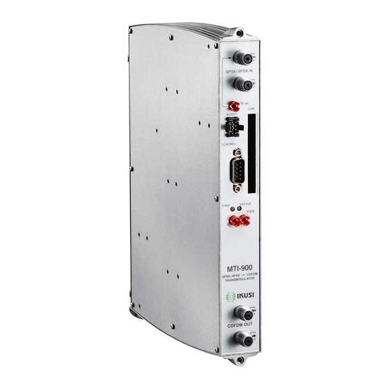
TN-031 How to setup MTI-900
FIRMWARE
MTI-900 firmware 1.93 or higher
HMS-120 firmware 1.106 or higher
The MTI can be configured with a programmer SPI-300 & firmware 3.14, or SPI-300 firmware 4.14 or 4.15
Figure 1 SPI-300 Screen
Figure 1 shows typical opening screen
Figure 2 indicates which buttons control function.
The Left hand and right hand bottom of the screen are controlled by selection buttons.
The direction arrows below selection buttons allow user to move left or right and up and down through the screen
selections
When SPI-300 is connected to the DB-9 on MTI-900, the SPI-300 will display the Start Screen
Figure 3 as follows:
Name of the module.
"Alarm" : Informs about the existence or not of module operating failures.
"Fx.x" : Version of the main firmware of the module (the firmware is the software stored in the module that
manages its basic running).
"fx.x" : Firmware version of the internal FPGA device.
"Acq" : "X" means that synchronization with the input signal is acquired.
Absence of synchronization is signalled with "0".
"BER" : Is the BER of the input signal channel
Doc ID: TN-031 How to setup a MTI-900 V1.docx
Prepared by: DN
MTI-900 SPI-300
Figure 2 SPI-300 Controls
Date: 12-June-2014
HMS-120
MTI-900
F01.93
Acq: 0
Approved by: DN
AUSTRALIAN HEAD
OFFICE
7 Amsted Road
Bayswater 3153
Ph: (03) 9720 8000
Fax: (03) 9720 7422
sales@ikusi.com.au
Selection Buttons
Direction arrows
Alarm : No
f01.08
BER: -
OK
Figure 3 Start Screen
Page:
1 of 5
Date: 12-June-2014
Advertisement
Table of Contents

Summary of Contents for IKUSI MTI-900
- Page 1 The direction arrows below selection buttons allow user to move left or right and up and down through the screen selections When SPI-300 is connected to the DB-9 on MTI-900, the SPI-300 will display the Start Screen Figure 3 as follows: ...
- Page 2 Set 4.Guard Interval = 1/16, Set 5. Constellation =64QAM, Set 6. Code Rate = 3/4 These setting can be altered to increase or decrease overall bandwidth of COFDM signal (must be less than 23Mb/s) Doc ID: TN-031 How to setup a MTI-900 V1.docx Page:...
- Page 3 At TS Processing menu, enter Control Module = X, Unref. PIDs = Auto, All Serv. = Block. If MTI-900 are used either standalone or grouped together without HMS-120 the Control module setting should change to X so LCN’s will display correctly...
- Page 4 120 that performs control function (last module at the right end of the IKUSUP bus 9 NID : 0 cascade). Data being entered in other MTI-900 don't take effect. Note that you must Send set NIT mode = NIT-pass to get same LCN as FTA.
- Page 5 Hw. is general hardware of the module. Ins. is the insertion of tables into the output stream. Tmp is the internal temperature of the module. Code is a global alarms code that is useful when contacting IKUSI's technical support. Inp. : 0...


Need help?
Do you have a question about the MTI-900 and is the answer not in the manual?
Questions and answers