IKUSI SPI-300 Basic Handling
To programme
classa and classb modules
Hide thumbs
Also See for SPI-300:
- Basic manual (56 pages) ,
- Setup manual (16 pages) ,
- Tech note (5 pages)
Advertisement
Quick Links
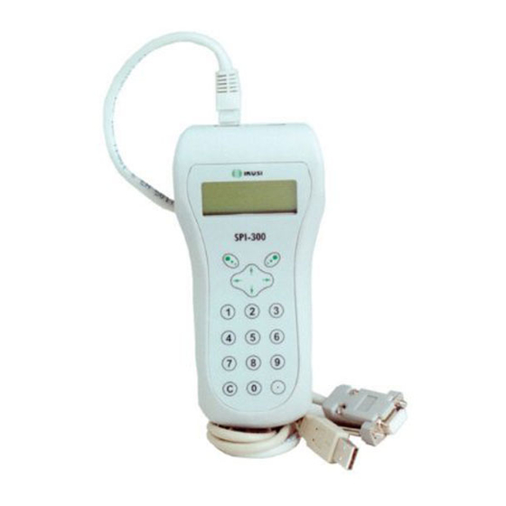
SPI-300
QPSK IN
QPSK IN
QPSK IN
QPSK IN
V
LNB
QPSK IN
V
LNB
V
LNB
V
LNB
V
LNB
STATUS
SYNC
STATUS
+12V
SYNC
STATU S
SYNC
+12V
STATU S
+12V
SYNC
VIDEO
STATU S
+12V
SYNC
VIDEO
+12V
SRF -10
0
VIDEO
ITE
0
L SATELL
VIDEO
SRF -10
DIGITA
RECEIV
ER
L SATELL
ITE
VIDEO
SRF -10
0
DIGITA
RECEIV
ER
LITE
SRF -10
0
L SATEL
DIGITA
RECEI VER
LITE
0
L SATEL
SRF -10
DIGITA
RECEI VER
RF OUT
LITE
DIGITA
L SATEL
RECEI VER
RF OUT
RF OUT
RF OUT
RF OUT
BASIC HANDLING
To Programme
ClassA and ClassB Modules
Accesories
The SPI-300 is supplied with the following accessories:
- 1 "RJ-45 / DB-9" interfacing cable to link the unit to the ClassA/ClassB modules.
- 1 "RJ45 / USB" interfacing cable to link to the MDI, SZB and STG modules.
- 1 CD-ROM with a) the particular PDF-format user guides to programme each of
the aforementioned modules and b) the software to update the firmwares of the
ClassA/ClassB modules and the one of the SPI-300 proper.
RJ-45 / DB-9 cable
RJ-45 / USB cable
Connecting the Cable
To programme ClassA and ClassB modules you must use the enclosed RJ-45 / DB-9
cable. The RJ-45 tip plugs in the rear socket of the SPI-300 and the DB-9 tip plugs in
the CONTROL socket of the module
SPI-300
RJ-45 / DB-9
Module ClassA
Using an Auxiliary Power Supply
The SPI-300 does not require batteries, it is
powered directly from the module to which is
connected. Only if you are going to perform a
firmware update through your PC, you need an
auxiliary +15V
/1A power supply. The DC cable
DC
of the power supply plugs in the rear jack
socket of the programming unit.
EN
SPI-300
CM K-6 00
CM K-6 00
CM K-6 00
CM K-6 00
CM K-6 00
CM K-6 00
CM K-6 00
CM K-6 00
SYN C
CM K-6 00
STA TUS
SYN C
C
STA TUS
SYN C
STA TUS
SYN C
RS -23
STA TUS
SYN C
2
STA TUS
RS -23
2
SYN C
RS -23
STA TUS
2
SYN C
RS -23
STA TUS
1
2
3
2
RS -23
SYN C
STA TUS
2
SYN C
RS -23
STA TUS
2
SY
RS -23
2
RS -23
2
4
5
6
RS -23
2
7
8
9
C
0
CD-ROM
Module ClassB
CM K-6 00
QPSK IN
V
LNB
US
SYNC
STAT
RS- 232
STATUS
SYNC
+12V
VIDEO
SDC- M201
E
DIGITAL
SATELLIT
R
RECEIVE
RF OUT
(+)
central conductor
DC cable of the
auxiliary power supply
PRESENTATION
This guide explains the Basic Handling of the SPI-300 (Ref. 4070) Programming
Unit to programme ClassA and ClassB headend modules from IKUSI. The
particular user guides for each type of module, which explain in detail the
respective programming processes, are shipped in PDF format in the enclosed
CD-ROM.
All programming processes are carried out through a guided menu that uses the
keypad of the SPI-300 :
SPI-300
1
2
3
4
5
6
7
8
9
C
0
1
1. User's Interface
1.1 - Screens ............................................................................ 5 - 7
1.2 - The Main Menu Screen ........................................................ 8
1.3 - Entering Data ........................................................................ 9
2. Programming the Modules
2.1 - Connecting the SPI-300 ...................................................... 10
2.2 - Detection of Module ............................................................ 10
2.3 - Parameter Setting ................................................................ 11
2.4 - Looking Up Information ....................................................... 12
2.5 - Using Module Configurations ....................................... 12 / 13
2.6 - Updating Module Firmware .......................................... 14 / 15
Appendix A — Firmware Update
A.1 - Installing Load Software on the PC .................................... 16
A.2 - Loading Firmware Files on the SPI-300 ...................... 17 / 18
A.3 - Updating SPI-300 Firmware ............................................... 19
3
Keys ↑ ↑ ↑ ↑ ↑ and ↓ ↓ ↓ ↓ ↓ :
- Vertical displacement of the slide.
- Modification of a parameter value.
- Change of page within a menu option.
Keys ← ← ← ← ← and → → → → → :
- Horizontal displacement of the slide.
- Change of the command displayed at the lower
left corner of the screen.
- Change of page in selection lists.
Keys
and
:
- Use of the commands displayed at the lower
corners of the screen (left and right,
respectively).
Numerical keys :
- Selection of menu option.
- Selection of parameter.
- Entry of parameter value.
Key "C" :
- Deletion of the character selected by the slide.
Key "." :
- Entry of decimal point.
Basic Handling
Index
2
4
Advertisement

Related Manuals for IKUSI SPI-300


Summary of Contents for IKUSI SPI-300
- Page 1 To programme ClassA and ClassB modules you must use the enclosed RJ-45 / DB-9 1.2 - The Main Menu Screen ............8 cable. The RJ-45 tip plugs in the rear socket of the SPI-300 and the DB-9 tip plugs in 1.3 - Entering Data ................ 9 the CONTROL socket of the module 2.
-
Page 2: User's Interface
DONE command just when the values have been sent. screens that allow to select options, adjust parameters and obtain diverse information. - DONE : The setting values are simply stored in the SPI-300, so that they remain 1.1 - Screens available either to be sent to the module (SEND command) or to constitute a All screens have a similar format. -
Page 3: Programming The Modules
↑ ( ó ↓ ). Each time the key is pressed the and status of the module are loaded on the SPI-300. A detection screen appears for a number is changed by a preestablished amount. If the key is held pressed, the short time, and next the display shows the Basic Information screen, which identifies change is effected fast. -
Page 4: Appendix A - Firmware Update
) to close the screen without creating any configuration. To perform an update process, first you must load the firmware file on the SPI-300 in the way that is explained in the Appendix A - Firmware Update (pages 16 to 19). - Page 5 A.2 - Loading Firmware Files on the SPI-300 The load of the firmware files on the SPI-300 is carried out from the PC on which you have installed the Load Software. Using the RJ-45 / DB-9 cable, connect the SPI-300 to the serial port of the computer.
Need help?
Do you have a question about the SPI-300 and is the answer not in the manual?
Questions and answers