Table of Contents
Advertisement
EVERLAST
POWERPLASMA S SERIES
CC
PAC
IGBT
1
~
PHASE
Operator's Manual for the PowerPlasma 60S, 70S, and 80S
Safety, Setup and General Use Guide
Rev. 3
0 00215-13
everlastwelders.com
Specifications and Accessories subject to change without notice.
1-877-755-9353
EVERLAST
329 Littlefield Ave. South San Francisco, CA 94080 USA
Advertisement
Table of Contents

Related Manuals for Everlast PowerPlasms S Series


Summary of Contents for Everlast PowerPlasms S Series
- Page 1 EVERLAST POWERPLASMA S SERIES IGBT PHASE Operator’s Manual for the PowerPlasma 60S, 70S, and 80S Safety, Setup and General Use Guide Rev. 3 0 00215-13 everlastwelders.com Specifications and Accessories subject to change without notice. 1-877-755-9353 EVERLAST 329 Littlefield Ave. South San Francisco, CA 94080 USA...
-
Page 2: Table Of Contents
The owner of this product assumes all liability for its use and maintenance. Everlast Power Equipment INC. does not warrant this product or this document for fitness for any particular purpose, for performance/accuracy or for suitability of application. -
Page 3: Letter To The Customer
Your unit registration is important should any information such as product updates or re- calls be issued. It is also important so that we may track your satisfaction with Everlast products and services. If you are unable to register by website, contact Everlast directly through the sales department through the main customer service number in your country. -
Page 4: Everlast Contact Information
Model number: ____________________________ Date of Purchase___________________________ EVERLAST Contact Information Everlast US: Everlast consumer satisfaction email: sales@everlastwelders.com Everlast Website: everlastwelders.com Everlast Technical Support: support@everlastwelders.com Everlast Support Forum: http://www.everlastgenerators.com/forums/index.php Main toll free number: 1-877-755 WELD (9353) 9am—5pm PST M-F 11am-4pm PST Sat. -
Page 5: Safety Precautions
Safe operation and proper maintenance is your responsibility. We have compiled this operator’s manual, to instruct you in basic safety, oper- ation and maintenance of your Everlast product to give you the best possible experience. Much of welding and cutting is based upon experience and com- mon sense. - Page 6 SAFETY PRECAUTIONS These safety precautions are for protection of safety and health. Failure to follow these guidelines may result in serious injury or death. Be careful to read and follow all cautions and warnings. Protect yourself and others. Welding and cutting processes produce high levels of ultraviolet (UV) radiation that can cause severe skin burn and damage.
- Page 7 SAFETY PRECAUTIONS WARNING! Persons with pacemakers should not weld, cut or be in the welding area until they consult with their physician. Some pacemakers are sensitive to EMF radiation and could severely malfunction while welding or while being in the vicinity of someone welding.
- Page 8 SAFETY PRECAUTIONS continued WARNING! Electrical shock can kill. Make sure all electrical equipment is properly grounded. Do not use frayed, cut or otherwise damaged cables and leads. Do not stand, lean or rest on ground clamp. Do not stand in water or damp areas while weld- ing or cutting.
-
Page 9: Introduction And Specifications
Section 1 Introduction and Specifications PowerPlasma 60S, 70S, and 80S 12 ft. S-75 Trafimet Torch Work Clamp Consumable Starter Kit (Qty. and items may vary) Regulator Assembly with Bracket NOTE: Accessory and consumable style and quantities are subject to change without notice. -
Page 10: Unit Specifications
Section 1 Introduction and Specifications Specification PowerPlasma 60S PowerPlasma 70S PowerPlasma 80S Inverter Type Analog, Siemens IGBT Analog, Siemens IGBT Analog, Siemens IGBT Module Construction Module Construction Module Construction Minimum/Maximum Rated Output 20 A/88 V - 60 A/108 V 20 A/88 V-70 A/110V 20 A/88 V-80 A/112 V Start Type Blow-Back Type... -
Page 11: General Overview
Section 1 Introduction and Specifications source to reduce the possibility of electrocution or shock. General overview: The new, redesigned PowerPlasma S– Never operate in standing water. This unit has a high series are non high frequency machines. The “blow- Open circuit voltage further necessitating safe operating back”... -
Page 12: Quick Setup Guide, Torch Connection
Section 2 QUICK SETUP AND USE GUIDE QUICK SETUP GUIDE: CONNECTIONS WORK (+) TORCH (-) CENTRAL CONNECTOR... -
Page 13: Rear Panel Gas Connection And Wiring
Section 2 QUICK SETUP AND USE GUIDE QUICK SETUP GUIDE: REAR CONNECTIONS AND WIRING (US/Canada) IMPORTANT: TO PREVENT AIR LEAKS, MAKE SURE TUBING ENDS ARE SQUARELY CUT AND FULLY INSERTED. TO RELEASE TUBING: PRESS GENTLY ON PLASTIC COLLAR SO THAT IT COMPRESSES INTO HOUSING AND THEN PULL TUBING OUT. 1~220 VAC PUSH TO CONNECT TUBING NOTE: WHEN ASSEMBLING AIR REGULATOR NOTICE THE MARKING S THAT ARE... -
Page 14: Compressor And Air Dryer Diagram
Section 2 QUICK SETUP AND USE GUIDE QUICK SETUP GUIDE: REAR CONNECTIONS AND WIRING Compressor and Dryer Diagram Compressor and Air hose w fittings (Customer Supplied) Regulator Assembly with built-in water trap and dirt filter (Included) 1/4” Automotive Universal style quick connector (Included) 1~220 VAC Air Dryer/Oil Filter... -
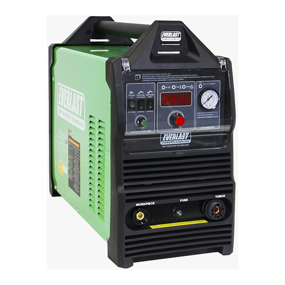
Page 15: Front Panel Features And Controls
Section 2 QUICK SETUP AND USE GUIDE FRONT PANEL FEATURES AND CONTROLS 1. AMP DISPLAY 12. ON/TEMP/O.C 2. AIR PRESSURE OK TO CUT 11. AIR FLOW FUNCTION 10. PILOT ARC OPERATION 3. AIR PRESSURE GAUGE 9. 2T/4T LOCK 4. AMP CONTROL 8. - Page 16 Cycle the machine on and off. If the light clears and cutting resumes, the fault has been cleared. If the unit will not work and/or the light remains on, contact Everlast Tech Support.
- Page 17 Section 2 QUICK SETUP AND USE GUIDE REAR PANEL FEATURES AND CONTROLS 1. CNC CONNECTION 2. 2-POLE POWER SWITCH 6. REGULATOR ASSY. 1~220 VAC 3. POWER CABLE 1 ~ 220/240V 1~220 V INLET 5. HF GROUND BOLT 4. GAS INLET...
-
Page 18: Rear Panel Features And Controls
Less than 5% is preferred. Operating the unit on square wave output or modified sine wave generators is strictly prohibited. Contact the manufacturer of the generator for this information. Everlast does not have an “approved” list of gener- ators. -
Page 19: Basic Theory And Function
Section 3 Basic theory and function The design of the blow back start may cause a slight delay in the arc as the air pressure must built inside the torch tubing and head to create the pressure needed to force the electrode off the nozzle seat. This may take up to two seconds. - Page 20 Section 3 Basic theory and function TIP: For longer consumable life do not use the pilot arc unnecessarily. Select the 3 second pilot arc feature and do not fire the torch unless you are near the metal and ready to cut. For expanded metal cutting be sure to select “Normal”...
- Page 21 Section 3 Basic theory and function RESULTS OF CUT AT FAST SPEED RESULTS OF CUT AT CORRECT SPEED, AIR PRESSURE AND TORCH ANGLE ROUGH, DISTINCT CUT LINES SPACED FAR APART SMOOTH, EVEN CUT LINES WITH A S REARWARD SWEEP NOTICEABLE SMALL, HARD DROSS MINIMAL EASY TO CLEAN DROSS RESULTS OF TOO MUCH CURRENT OR RESULTS OF CUT AT SLOW SPEED...
- Page 22 Section 3 Basic theory and function AN EXAMPLE OF CUTTING A LEAD-IN WHEN CUTTING OUT A DISK SHAPED OBJECT AN EXAMPLE OF CUTTING A LEAD-IN WHEN CUTTING HOLE IN AN OBJECT When cutting an object, particularly a pattern shape, where the torch must pierce or re-fire in-line at an inter- section of a cut, a lead-in cut should be employed.
-
Page 23: Torch
(Trafimet Addendum) *Everlast is not the manufacturer of the Trafimet S-75 torch, nor is it affiliated with Trafimet other than its role as an OEM supplier of torches on PowerPlasma S-Series units. Not all items, accessories and parts depicted are available directly through Everlast. These are items supplied through nationwide Trafimet dealers and resalers. Diagram provided courtesy of Trafimet. -
Page 24: Cnc Connector Pin-Out
*Everlast does not particularly endorse or recommend these brands and is not affiliated with them in anyway. They are mentioned as a common reference only. For specific recommendations regarding connection, contact the manufacturer of the CNC equipment/controllers. -
Page 25: Troubleshooting
Make sure swirl ring is not cracked. Arc will try to start if touched to the metal, but no air Stuck or dirty solenoid valve. Contact Everlast. flow while switch is pressed. Air flows continuously.
Need help?
Do you have a question about the PowerPlasms S Series and is the answer not in the manual?
Questions and answers