
Related Manuals for janitza UMG 806


Summary of Contents for janitza UMG 806
- Page 1 Modular Power Analyzer UMG 806 User manual and technical data (Firmware 1.18) Janitza electronics GmbH Vor dem Polstück 6 35633 Lahnau, Germany Support tel. +49 6441 9642-22 Email: info@janitza.com www.janitza.com...
- Page 2 UMG 806 www.janitza.de UMG 806 Modular multifunctional meter for recording energy quantities Doc. no.: 2.064.005.2b Date: 05/2020 The German version is the original edition of the documentation...
- Page 3 Nonetheless, we wish to point out that updates of this document are not always possible at the same time as technical refinements are implemented in our products. Please see our website under www.janitza.de for the current version. Please see our website under www.janitza.de for the current version.
-
Page 4: Table Of Contents
UMG 806 www.janitza.de Table of contents 1. Information on the device and the user manual 1. 1 Disclaimer 1. 2 Copyright notice 1. 3 Technical changes 1. 4 About this user manual 1. 5 Defective device/disposal 2. Safety 2. 1 Display of warning notices and safety information 2. - Page 5 UMG 806 4. Structure of the device 4. 1 Front panel and display 4. 2 Front view / side view 4. 3 Identification of the device (rating plate) 5. Mounting 5. 1 Installation location 5. 2 Mounting orientation and attachment 6.
- Page 6 UMG 806 www.janitza.de 8. PC connection 8. 1 Connection to a PC 9. Operation and button functions 9. 1 Controls 9. 2 Function buttons 9. 3 Operation 9. 3. 1 Display mode 9. 3. 2 Configuration mode 9. 4 Password 9.
- Page 7 11. 7 Checking measurement 11. 8 Checking individual power 11. 9 Checking summation power 12. Connection example, UMG 806 13. Expansion modules 13. 1 Module types 13. 1. 1 806-EC1 module 13. 1. 2 806-ED1 module 13. 1. 3 806-EI1 module 13.
- Page 8 14. 3 Service 14. 4 Device adjustment 14. 5 Clock/Battery 14. 6 Procedure in the event of a malfunction 15. Technical data 15. 1 Technical data, UMG 806 15. 2 Performance characteristics of functions 15. 3 Technical data of the modules...
- Page 9 UMG 806...
-
Page 10: Information On The Device And The User Manual
Technical changes · Make sure that your device matches the user manual. · This user manual applies to the UMG 806. Separate validities and distinctions are marked. · First read and understand the documents associated with the product. · Keep the documents associated with the product available for the entire service life and pass them on to any possible subsequent users. -
Page 11: Defective Device/Disposal
· When doing so, please bear the terms for transportation in mind. INFORMATION Please return defective or damaged devices to Janitza electronics GmbH in accordance with the shipping instructions for air or road freight (complete with accessories). Observe special regulations for devices with built-in... -
Page 12: Safety
UMG 806 www.janitza.de Safety Hazard levels The chapter on Safety contains information which must be observed to ensure your personal safety Warning and safety information is marked by a and avoid material damage. warning symbol, and the hazard levels are shown... -
Page 13: Product Safety
UMG 806 Product safety WARNING The device reflects current engineering practice Risk of injury due to electrical voltage! and accepted safety standards, but hazards can Severe bodily injury or death can result! Therefore arise nonetheless. please abide by the following: ·... -
Page 14: Electrically Qualified Personnel
UMG 806 www.janitza.de Electrically qualified personnel Safety information for handling current transformers and measurement To avoid bodily injury and material damage, only devices with residual current electrically qualified personnel are permitted measurement to work on the devices and their components,... -
Page 15: Handling Batteries/Accumulators
The battery used in the device may cause fire or burns if used improperly. · Only replace the battery with the same type or types recommended by Janitza! · Observe the polarity when installing the battery! · Remove batteries only with non-conductive tools (e.g. -
Page 16: Product Description
UMG 806 www.janitza.de Product description Device description CAUTION The device is a multifunctional network analyzer Malfunction and damage of the device or risk of and is suitable for: injury due to improper connection. · Measurements and calculations of electrical Improperly connected devices can deliver incorrect... -
Page 17: Intended Use
UMG 806 Intended use The device is: · Only for use in the industrial sector. · Intended for installation in switchboard cabinets and small installation distributors. · Not intended for installation in vehicles! Use of the device in non-stationary equipment... -
Page 18: Performance Characteristics
Performance characteristics EU conformity declaration Please see the EU declaration of conformity General posted at www.janitza.de for the laws, standards · DIN rail measurement device with the dimensions and directives applied by Janitza electronics 90 x 90 x 64 mm GmbH for the devices. -
Page 19: Operating Concept
® Use the GridVis network analysis software ® available at www.janitza.de to read out data for analysis. To do so, connect a PC to your measurement device via the Ethernet interface. Performance characteristics of the GridVis ®... -
Page 20: Overview Of The Range Of Functions
UMG 806 www.janitza.de 3.11 Overview of the range of functions 3.11.1 Configuration on the device (via 2 buttons) · Password protection · Module enhancements · Current transformer primary / secondary · Voltage transformer primary / secondary · Fieldbus parameters · Digital output ·... - Page 21 UMG 806...
-
Page 22: Structure Of The Device
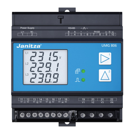
UMG 806 www.janitza.de Structure of the device Front panel and display Fig.: Front panel with display Fig.: Device front with screw terminal covers and display - 3D... - Page 23 UMG 806 Item Function/Designation Supply voltage connection Setup button RS-485 interface Digital output (active energy) Temperature measurement input (PT100) Residual current measurement input I5 Module locking LED (communication) Button 1 Module communication interface Button 2 LED (pulse activity) Module locking...
-
Page 24: Front View / Side View
UMG 806 www.janitza.de Front view / side view 90 mm (3.54 in) 63.5 mm (2.5 in) -
Page 25: Identification Of The Device (Rating Plate)
Identification of the device (rating plate) UMG 806 1402015 Aux: 80..270V, 50/60Hz 80..270V 300V CAT III 1958220956 Made in China • www.janitza.com Item Designation Description Designation of origin/ Country of origin and manufacturer’s web address. web address Operational data Supply voltage and maximum power consumption. -
Page 26: Mounting
35 mm mounting rail (for type, see technical data) according to DIN EN 60715. The mounting orientation is arbitrary. Mounting orientation and attachment Proceed as follows to mount the UMG 806 on the mounting rail: 1. Push in the bottom bolt of the clamping mechanism. - Page 27 UMG 806...
-
Page 28: Grid Systems
UMG 806 www.janitza.de Grid systems Suitable grid systems and maximum rated voltages according to DIN EN 61010-1/A1: Three-phase 4-conductor systems Three-phase three-conductor systems with grounded neutral conductor with grounded phase : 230 V / 400 V 400 V Three-phase 4-conductor systems... -
Page 29: Installation
“Transformers for measuring purposes", specifically during testing and commissioning of the Janitza measurement device, the Janitza component and your system. AC/DC Grounding Voltage measurement of the Auxiliary supply system UMG 806 Fig. Schematic diagram, UMG 806 in a TN network... -
Page 30: Three-Phase 3-Conductor Network
Auxiliary supply UMG 806 Fig. Schematic diagram, UMG 806 in an IT network without N. 230/400V 50/60Hz Impedance AC/DC Grounding of the system Voltage measurement Auxiliary supply UMG 806 Fig. Schematic diagram, UMG 806 in an IT network with N. -
Page 31: Disconnect Switch
UMG 806 Disconnect switch INFORMATION When installing in a building, provide a suitable The fuse is a line protection - it is not a device disconnect switch for the supply voltage in order protection! to disconnect your system and thus your device from the supply of power. -
Page 32: Voltage Measurement
UMG 806 www.janitza.de Voltage measurement INFORMATION The device has 4 voltage measurement inputs As an alternative to the fuse and isolation device, and V ) and is suitable for various you can use a line circuit breaker. connection variants. WARNING 7.4.1... -
Page 33: Current Measurement
UMG 806 Current measurement WARNING The device: Risk of injury due to high currents and high · Measures current exclusively via current electrical voltages! transformers. Severe bodily injury or death can result from: · Does not measure DC currents. -
Page 34: Connection Variants
UMG 806 www.janitza.de 7.5.1 Connection variants Three-phase 4-conductor system Three-phase 4-conductor system Current measurement via 3 current transformers Measurement via 3 current and 3 voltage transformers Three-phase three-conductor system Three-phase three-conductor system Current measurement via 2 current transformers Measurement via 2 current and 2 voltage transformers... -
Page 35: Summation Current Measurement
UMG 806 7.5.2 Summation current measurement For a summation current measurement via two current transformers, first set their total ratio on the device (for setting the current transformer ratios, see section "11.4 Configuring current transformers" on page 33). Example: The current is measured via two current transformers. -
Page 36: Residual Current Measurement (Rcm)
(RCM) for monitoring device against electric shock! alternating currents and pulsating direct currents. INFORMATION Suitable for recording residual currents > 100 mA in combination with Janitza residual current transformers. 7.6.1 Current direction of the residual current transformers For residual current measurement with current 0.1..40 mA... -
Page 37: Residual Current Transformer Example
Use wiring designed for an operating temperature of up to 80 °C (176 °F)! 7.6.3 Connection example - Residual current monitoring 11 12 13 14 15 16 17 18 UMG 806 Fig. Connection example, UMG 806 with residual current monitoring... -
Page 38: Temperature Measurement
UMG 806 www.janitza.de Temperature measurement Example of temperature sensor: The UMG 806 has a temperature measurement A temperature sensor is to measure near input. The temperature is measured via terminals 7 uninsulated power lines in a 300 V CAT III network. -
Page 39: Rs-485 Interface (Serial Interface)
2-pole screw contact and communicates using termination resistor. A termination resistor must be the Modbus RTU protocol. set for termination for a UMG 806 at the beginning or end of a bus segment, (see section "Termination For the connection capacity of the terminals, see resistors / Termination"). -
Page 40: Shielding
UMG 806 www.janitza.de 7.8.2 Termination resistors/Termination 7.8.1 Shielding For connections via the interfaces, use a twisted Terminate the beginning and end of your bus and shielded cable and observe the following for segments with termination resistors (120 Ω/0.25 W the shielding: - see section "Bus structure (bus segment)”). -
Page 41: Bus Structure (Bus Segment)
· Devices with bus termination switched on must be powered. Fig. Representation of a bus structure Master Slave Slave Slave Repeater Slave Slave Slave Slave - Power supply necessary Master - e.g. UMG 605 - Bus terminator on Slave - e.g. UMG 806... -
Page 42: Digital Output
UMG 806 www.janitza.de Digital output ATTENTION The device has 1 digital output, which Transmission error and material damage due to · Is electrically isolated from the evaluation electrical malfunction. electronics via an optocoupler. With a cable length of more than 30 m, there is ·... -
Page 43: Pc Connection
PC (with The DHCP server automatically assigns IP GridVis software installed) are described below. addresses to the device and the PC. ® PC with UMG 806 with GridVis ® 1. Connection via interface converter: EC1 module PC with GridVis ®... -
Page 44: Operation And Button Functions
· In configuration mode, the character appears on the display. Fig. UMG 806 measuring display "Voltage L1-N, L2-N and L3-N" and function buttons. To switch back to the display mode: Function buttons · Press buttons 1 and 2 simultaneously for 1 s. -
Page 45: Overview Of Measuring Display (Display Mode)
UMG 806 Overview of measuring display (display mode) The measurement device measures electrical quantities such as voltage, current, power, power factor, frequency, energy, harmonics, asymmetries or extreme values. Some of these electrical quantities can only be read out via the communication interface. More detailed information can be found in the Modbus address list. -
Page 46: Examples Of Basic Measuring Displays
UMG 806 www.janitza.de Examples of basic measuring displays Phase voltage Total active power U L1 = 200.0 V ∑P = 875 W U L2 = 100.0 V U L3 = 50.0 V Mains voltage Total reactive power ∑Q = 1515 var U L1-L2 = 264.4 V... -
Page 47: Examples Of Energy Measurement
UMG 806 Example of time display Examples of energy measurement Date time Active energy applied displayed EP = 30.784 kWh October 11, 2017, 13h 28m 58s Active energy deliv- ered 9.10 Example of active EI1 module EP- = 50.430 kWh 1st analog input Id1 = 21.00 mA... -
Page 48: 10. Configuration
UMG 806 www.janitza.de 10. Configuration 10.1 Configuration mode 10.2 Configuration The configuration mode is used to configure the · Press and hold buttons 1 and 2 simultaneously parameters necessary for the operation of the for 1 s to switch between the display and device. -
Page 49: Configuring The Current Transformer Ratios
UMG 806 10.2.2 Configuring the current Parameter address transformer ratios Value of the The UMG 806 has 4 current measurement inputs primary current (I1 to I4) and one residual current measurement (100 A) input (I5). · The default setting of all current transformer ratios of the device (I1-I4 and I5) is 5 A / 5 A. -
Page 50: Example: Configuring The Current Transformer Ratios Of Residual Current Measurement Input I5 (700:1)
UMG 806 www.janitza.de 10.2.4 Example: Configuring the current transformer ratios of residual current measurement input I5 (700:1) · Press and hold buttons 1 and 2 simultaneously for 1 s to switch between the display and configuration modes. · Enter a password in the display using ·... -
Page 51: Configuring The Voltage Transformer Ratios
10.2.5 Configuring the voltage transformer Parameter address ratios Value of the The UMG 806 has 4 voltage measurement inputs primary voltage (V1 - V3 and VN). Of these, you can configure the (800 V) inputs L1 (V1) to L3 (V3). -
Page 52: Configuring The Rs-485 Interface (Modbus)
UMG 806 www.janitza.de 10.2.7 Configuring the RS-485 interface 10.2.8 Configuring the Ethernet interface (Modbus) INFORMATION To operate the device via the RS-485 interface (see section „7.8 RS-485 interface (serial interface)“ The description of the Ethernet interface on page 39), configure the following parameter (806-EC1 module) can be found in section “13.7.2... - Page 53 UMG 806...
-
Page 54: Parameter List
UMG 806 www.janitza.de 10.3 Parameter list Address Format Designation Setting range Unit Default setting uint32 Current transformer primary, I1..I3 1 .. 9999999 uint16 Current transformer secondary, I1..I3 1 .. 6 uint32 Voltage transformer primär, L1..L3 1 .. 9999999 uint16 Voltage transformer secondary, L1.. - Page 55 UMG 806 Address Format Designation Setting range Unit Default setting uint16 DHCP mode 0 = fixed IP 1 = DHCP client uint8 IP address, xxx --- --- --- 0 .. 255 uint8 IP address, --- xxx --- --- 0 .. 255...
- Page 56 UMG 806 www.janitza.de Address Format Designation Setting range Unit Default setting uint16 Device password 0 .. 9999 0000 0 = No password configured uint8 EC1 module activation 0 = EC1 inactive, 1 = EC1 active uint8 ED1 module activation 0 = ED1 inactive, 1 = ED1 active...
- Page 57 UMG 806...
- Page 58 UMG 806 www.janitza.de 11. Commissioning INFORMATION WARNING Before commissioning, delete any production- Risk of injury due to electrical voltage! related contents of the energy meters (see section If the device is exposed to surge voltages above “10.3 Parameter list” on page 54).
- Page 59 UMG 806 11.4 Measured current 11.7 Checking measurement The device: Correctly connected voltage and current · Measures current exclusively via current measurement inputs result in correctly calculated transformers. and displayed individual and summation power · Is designed for the connection of current readings.
- Page 60 UMG 806 www.janitza.de 12. Connection example, UMG 806 PT100 RS232 RS485 PT100 AI1+ AI2+ AI3+ AI4+ AIC Versorgungs- RS485 Energie Impuls/ Temperatur/ Analoge Eingänge/Analog in spannung/ Energy pulse Temperature Power supply UMG 806 Modul 806-EI1 Relaisausgänge/Relais outp Spannungsmessung/ Strommessung/Current measurement...
- Page 61 UMG 806 13. Expansion modules 13.1.3 806-EI1 module The following optional expansion modules can be used to extend the functionality of the basic device The 806-EI1 expansion module (the basic device only supports one extension · Extends the functional range of the basic device module per module type): by an additional 4 analog inputs.
- Page 62 INFORMATION When setting up your meter and module topology, note that: · The UMG 806 as a basic device allows the installation of one module type each (maximum 1 x EC1, 1 x ED1, 1 x EI1). · For communication between the basic device...
- Page 63 3. Plug in the module (the plug is recessed on the side of the UMG, the socket is on the module). 6. The UMG 806 can be combined with one 806- EC1, 806-EI1 or 806-ED1. 4. Check the connection of the UMG to the...
- Page 64 UMG 806 www.janitza.de 13.3 Front / side views 13.3.1 806-EC1 module 13.3.2 806-ED1 module...
- Page 65 UMG 806 13.3.3 806-EI1 module 13.4 Connection examples 13.4.1 806-ED1 module 13.4.2 806-EI1 module...
- Page 66 UMG 806 www.janitza.de 13.5 Configure/activate module 13.6 Display examples The basic device has expansion modules for 13.6.1 ED1 module additional functions (see section „13. Expansion modules “ on page 61). To configure or activate expansion modules, proceed as follows: Status of the digital input ·...
- Page 67 · Always keep the meter firmware up to date and DHCP mode protect the communication to the meter with · Use DHCP to configure your UMG 806 with an external firewall. Close unused ports. the 806-EC1 module for incorporation into an ·...
- Page 68 Connection examples 806-EC1 module UMG 806 Patch Patch cable cable Switch Fig. Connection example: UMG 806 with 806-EC1 module and PC require a fixed IP address (parameter 205 = 0). 806-EC1 module DHCP UMG 806 server Patch Patch cable...
- Page 69 UMG 806 13.8 Relay outputs of modules ED1 and EI1 You can configure the relay outputs in the following parameter addresses: The relay outputs have two operating modes: Address Designation 1. Alarm control EI1 DO1 mode If the relay mode "Alarm" (parameter address...
- Page 70 UMG 806 www.janitza.de 13.8.1 Table "Parameters of the alarm U unb - lower limit value elements" - Parameter address 412 U unb - upper limit value Table: Contents of parameter address 412 I unb - lower limit value (alarm elements)
- Page 71 UMG 806 13.8.2 Alarm elements and units of the alarm limit values Unit of the Alarm element (designation/formula variable) relevant alarm value Ua (V1), Ub (V2), Uc (V3), Un (Vn), Uab (V12), Ubc (V23), Uca (V31), Ul (VI - any mains voltage) Voltage 0.1 V...
- Page 72 UMG 806 www.janitza.de 14. Service and maintenance 14.2 Front panel foil and display Prior to outbound delivery, the device is subjected to various safety tests and is marked with a seal. Please note the following for the care and cleaning...
- Page 73 The battery used in the device may cause fire or burns if used improperly. · Only replace the battery with the same type or types recommended by Janitza! · Observe the polarity when installing the battery! · Remove batteries only with non-conductive tools (e.g.
- Page 74 UMG 806 www.janitza.de 14.6 Procedure in the event of a malfunction Failure mode Cause Remedy External fuse for the supply voltage has No display Replace fuse. tripped. No measured voltage connected. Connect measured voltage. No current display. No measured current connected.
- Page 75 UMG 806 15. Technical data 15.1 Technical data, UMG 806 General Net weight 300 g (0.66 lb) Approx. B = 90 mm (3.54 in), H = 90 mm (3.54 in), Device dimensions D = 63.5 mm (2.5 in) Battery...
- Page 76 UMG 806 www.janitza.de Voltage measurement 3-phase 4-conductor systems with rated voltages up to 230 V LN / 400 V LL (+/-10%) acc. to IEC 3-phase 3-conductor systems (grounded) with rated voltages up to 400 V LL (+/-10%) acc. to IEC...
- Page 77 UMG 806 Digital outputs Energy pulse output Switching voltage max. 35 V DC Switching current max. 10 mA eff DC Response time approx. 500 ms Pulse width 80 ms ±20% Digital output (energy pulses) max. 10 Hz Temperature measurement...
- Page 78 UMG 806 www.janitza.de Connecting capacity of the terminals (voltage measurement) Connectible conductors. Only connect one conductor per terminal point! Single core, multi-core, fine-stranded 0.2 - 4 mm , AWG 24-12 Wire ferrules (insulated/non-insulated) 0.25 - 2.5 mm , AWG 23-14 Strip length 7 mm (0.2756 in)
- Page 79 UMG 806 15.2 Performance characteristics of functions Function Sign Accuracy Display range Voltage 0-999.9 kV Current 0-99,99 kA Active power 0-9999 MW Reactive power 0-9999 Mvar Apparent power 0-9999 MVA Power factor 0-1.000 Frequency ±0.01 Hz 45.00 Hz-65.00 Hz Active energy 0.5 s...
- Page 80 UMG 806 www.janitza.de 15.3 Technical data of the modules General 806-EC1 806-EI1 806-ED1 Net weight 82g (0.18 lb) 91g (0.20 lb) 82 g (0.18 lb) B = 36 mm (1.42 in), H = 90 mm (3.54 in), Device dimensions T = 63.5 mm (2.5 in)
- Page 81 UMG 806...
- Page 82 Janitza electronics GmbH Vor dem Polstück 6 D-35633 Lahnau Support tel. +49 6441 9642-22 Email: info@janitza.de info@janitza.de | www.janitza.de Subject to technical changes. The current version of the document can be found in the download area at www.janitza.de.
Need help?
Do you have a question about the UMG 806 and is the answer not in the manual?
Questions and answers