Sign In
Upload
Manuals
Brands
janitza Manuals
Measuring Instruments
UMG 806
janitza UMG 806 Energy Measurement Manuals
Manuals and User Guides for janitza UMG 806 Energy Measurement. We have
2
janitza UMG 806 Energy Measurement manuals available for free PDF download: User Manual And Technical Data
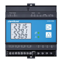
janitza UMG 806 User Manual And Technical Data (92 pages)
Modular Power Analyzer
Brand:
janitza
| Category:
Measuring Instruments
| Size: 6.68 MB
Table of Contents
Table of Contents
4
Information on the Device and the User Manual
10
Disclaimer
10
Copyright Notice
10
Technical Changes
10
About this User Manual
10
Defective Device/Disposal
11
Safety
12
Display of Warning Notices and Safety Information
12
Hazard Levels
12
Product Safety
13
Dangers When Handling the Device
13
Electrically Qualified Personnel
14
Warranty in the Event of Damage
14
Safety Information for Handling Current Transformers and Measurement Devices with Residual Current Measurement
14
Handling Batteries/Accumulators
15
Product Description
16
Device Description
16
Incoming Goods Inspection
16
Intended Use
17
Performance Characteristics
18
EU Conformity Declaration
18
Scope of Delivery
18
Accessories
18
Transformer
19
Operating Concept
19
Gridvis ® Network Analysis Software
19
Overview of the Range of Functions
20
Configuration on the Device (Via 2 Buttons)
20
Communication
20
Measured Values / Functions
20
Structure of the Device
22
Front Panel and Display
22
Front View / Side View
24
Identification of the Device (Rating Plate)
25
Mounting
26
Installation Location
26
Mounting Orientation and Attachment
26
Grid Systems
27
Installation
28
Nominal Voltages
28
Three-Phase 4-Conductor Network
28
Three-Phase 3-Conductor Network
29
Disconnect Switch
30
Supply Voltage
30
Voltage Measurement
31
Overvoltage
31
Mains Frequency
31
Current Measurement
32
Measuring Variants
33
Summation Current Measurement
34
Ammeter
34
Residual Current Measurement (RCM)
34
Current Direction of the Residual Current Transformers
35
Residual Current Transformer Example
35
Connection Example - Residual Current Monitoring
36
Temperature Measurement
37
RS-485 Interface
38
Shielding
39
Termination Resistors/Termination
39
Bus Structure (Bus Segment)
40
Digital Output
41
PC Connection
42
Connection to a PC
42
Operation and Button Functions
43
Controls
43
Function Buttons
43
Operation
43
Display Mode
43
Configuration Mode
43
Password
43
Overview of Measuring Display (Display Mode)
44
Examples of Basic Measuring Displays
45
Examples of Energy Measurement
46
Examples of Power Quality
46
Example of Time Display
46
Example of Active EI1 Module
46
Example of Active ED1 Module
46
Configuration
47
Configuration Mode
47
Configuring the Network System
47
Configuring the Current Transformer Ratios
48
Example: Configuring the Current Transformer Ratios of Residual Current Measurement Input I5 (700:1)
49
Configuring the Voltage Transformer Ratios
50
Example: Configuring the Voltage Transformer Ratios
50
Configuring the RS-485 Interface (Modbus)
51
Configuring the Ethernet Interface
51
Parameter List
52
Commissioning
56
Supply Voltage
56
Measured Voltage
56
Frequency Measurement
56
Measured Current
57
Checking the Phase Assignment
57
Checking the Power Measurement
57
Checking Measurement
57
Checking Individual Power
57
Checking Summation Power
57
Connection Example, UMG 806
58
Expansion Modules
59
Module Types
59
806-EC1 Module
59
806-ED1 Module
59
806-EI1 Module
59
Installing the Modules
61
Front / Side Views
62
806-EC1 Module
62
806-ED1 Module
62
806-EI1 Module
63
Connection Examples
63
806-ED1 Module
63
Module Detection
64
Display Examples
64
ED1 Module
64
EI1 Module
64
EC1 Module
64
Front Leds and Reset Button
64
Configuring the Ethernet Interface
65
Relay Outputs of Modules ED1
66
And EI1
66
Automatic Alarm Control (Example for EI1-RO1)
66
Manual Control Via Modbus Addresses
67
Alarm Elements and Units of the Alarm Limit Values
69
EC1 Module Homepage
70
Log in
70
Overview
70
Home
72
Measured Value Display
72
Settings
75
Tcp/Ip
75
Modbus
76
Current Transformer (CT) / Voltage Transformer (VT) Ratios
77
Password
78
Firmware Update
79
General Information
80
Service and Maintenance
82
Repair and Calibration
82
Front Panel Foil and Display
82
Service
82
Device Adjustment
82
Clock/Battery
83
Procedure in the Event of a Malfunction
84
Technical Data
86
Technical Data, UMG 806
86
Performance Characteristics of Functions
90
Technical Data of the Modules
91
Advertisement
janitza UMG 806 User Manual And Technical Data (82 pages)
Modular Power Analyzer
Brand:
janitza
| Category:
Measuring Instruments
| Size: 4.21 MB
Table of Contents
Table of Contents
4
Information on the Device and the User Manual
10
Disclaimer
10
Copyright Notice
10
Technical Changes
10
About this User Manual
10
Defective Device/Disposal
11
Safety
12
Display of Warning Notices and Safety Information
12
Hazard Levels
12
Product Safety
13
Dangers When Handling the Device
13
Electrically Qualified Personnel
14
Warranty in the Event of Damage
14
Safety Information for Handling Current Transformers and Measurement Devices with Residual Current Measurement
14
Handling Batteries/Accumulators
15
Product Description
16
Device Description
16
Incoming Goods Inspection
16
Intended Use
17
Performance Characteristics
18
EU Conformity Declaration
18
Scope of Delivery
18
Accessories
18
Transformer
18
Operating Concept
19
Gridvis Network Analysis Software
19
Overview of the Range of Functions
20
Configuration on the Device (Via 2 Buttons)
20
3.11.2 Communication
20
3.11.3 Measured Values / Functions
20
Structure of the Device
22
Front Panel and Display
22
Front View / Side View
24
Identification of the Device (Rating Plate)
25
Mounting
26
Installation Location
26
Mounting Orientation and Attachment
26
Grid Systems
28
Installation
29
Nominal Voltages
29
Three-Phase 4-Conductor Network
29
Three-Phase 3-Conductor Network
30
Disconnect Switch
31
Supply Voltage
31
Voltage Measurement
32
Overvoltage
32
Mains Frequency
32
Current Measurement
33
Connection Variants
34
Summation Current Measurement
35
Ammeter
35
Residual Current Measurement (RCM)
36
Current Direction of the Residual Current Transformers
36
Residual Current Transformer Example
37
Connection Example - Residual Current Monitoring
37
Temperature Measurement
38
RS-485 Interface (Serial Interface)
39
Shielding
40
Termination Resistors/Termination
40
Bus Structure (Bus Segment)
41
Digital Output
42
PC Connection
43
Connection to a PC
43
Operation and Button Functions
44
Controls
44
Function Buttons
44
Operation
44
Display Mode
44
Configuration Mode
44
Password
44
Overview of Measuring Display (Display Mode)
45
Examples of Basic Measuring Displays
46
Examples of Energy Measurement
47
Examples of Power Quality
47
Example of Time Display
47
Example of Active EI1 Module
47
Example of Active ED1 Module
47
10. Configuration
48
Configuration Mode
48
10.2.1 Configuring the Network System
48
Configuring the Current Transformer Ratios
49
Example: Configuring the Current Transformer Ratios of Residual Current Measurement Input I5 (700:1)
50
Configuring the Voltage Transformer Ratios
51
Example: Configuring the Voltage Transformer Ratios
51
Configuring the RS-485 Interface (Modbus)
52
10.2.8 Configuring the Ethernet Interface
52
Parameter List
54
Advertisement
Related Products
janitza UMG 801
janitza UMG 804
janitza UMG505
janitza UMG 96 RM-P
janitza UMG 96 RM-M
janitza UMG 96S
janitza UMG 103
janitza UMG 96-PA
janitza UMG 604
Janitza UMG96L
janitza Categories
Measuring Instruments
Control Unit
Controller
Touch Panel
Transformer
More janitza Manuals
Login
Sign In
OR
Sign in with Facebook
Sign in with Google
Upload manual
Upload from disk
Upload from URL