Table of Contents

Related Manuals for janitza UMG 509


Summary of Contents for janitza UMG 509
- Page 1 Power Quality Analyser UMG 509 Operation manual and technical data Janitza electronics GmbH Vor dem Polstück 1 D-35633 Lahnau Support Tel. 0049 6441 9642-22 Fax 0049 6441 9642-30 e-mail: info@janitza.com Website: http://www.janitza.com...
-
Page 2: Table Of Contents
UMG 509 Table of contents General information Operation Inspection on receipt Meaning of the keys Scope of delivery UMG 509 Measured value display Available accessories "Home" measured value display Product description Selecting a measured value display Proper use View additional information UMG 509 features Deleting min./max. - Page 3 UMG 509 Applying the residual current Checking the power measurement Checking the communication Measurement range exceeded (overload) RS485 interface Profibus Digital in-/outputs Service and maintenance Service Device calibration Calibration intervals Firmware update Battery Technical data Function parameters Declaration of conformity...
-
Page 4: General Information
- in whole or in part, by mechanical or electronic means - nor otherwise duplicated or republished, without the binding written permission Janitza electronics GmbH, Vor dem Polstück 1, D 35633 Lahnau, Germany. Trademarks All trademarks and the resulting rights are the property of their respective owners. - Page 5 UMG 509 Meaning of symbols This manual uses the following pictograms: Dangerous voltage! Ground wire connection. Risk to life or serious injury. Before commencing work on the system and the device, they must first be de-energised. Inductive. The current lags behind the voltage.
- Page 6 UMG 509 Instructions on use Please read this operation manual as well as all other Additional legal and safety regulations required for publications that must be consulted for working with the respective application are to be followed during this product (in particular, for the installation, operation the use of the device.
-
Page 7: Inspection On Receipt
UMG 509 Inspection on receipt Concerning this operation manual This operation manual is part of the product. The prerequisites of faultless, safe operation of this • Read the operation manual before using the device. device are proper transport and proper storage, •... -
Page 8: Scope Of Delivery Umg 509
33.03.194 Operation manual 51.00.116 CD with following content - GridVis programming software - GridVis functional description - UMG 509, GSD file "U5090F15.GSD" 10.01.855 Screw-type terminal, pluggable, 2-pole (auxilliary power) 10.01.847 Screw-type terminal, pluggable, 5-pole (voltage measurement 1-4) 10.01.853 Screw-type terminal, pluggable, 8-pole (current measurement 1-4) 10.01.873... -
Page 9: Product Description
30 mA. The UMG 509 can be used in 2, 3 and 4-conductor networks and in TN and TT networks. The current measurement inputs 1–4 of the UMG 509 are connected via external ../1A or ../5A current... -
Page 10: Umg 509 Features
UMG 509 UMG 509 features General information • Continuous monitoring of residual currents • Front panel integration device with dimensions with failure monitoring 144 x 144 mm • Temperature measurement • Connection via pluggable screw terminals • Working measurement, measurement uncertainty •... -
Page 11: Measuring Process
GridVis network analysis software The UMG 509 measures continuously and calculates The UMG 509 can be programmed and read out using the all effective values over a 200 ms interval. The device GridVis network analysis software included in the scope measures the real effective value (TRMS) of the voltages of the delivery. -
Page 12: Connection Variants
Direct connection of a UMG 509 to a PC via Ethernet. converter: UMG 509 UMG 509 (gedrehtes Patchkabel) Connection of a UMG 96RM via a UMG 509 as a gateway Connection of a UMG 509 to a PC via Ethernet. (gedrehtes Patchkabel) UMG 509 UMG 509... -
Page 13: Installation
UMG 509 Installation Position of installation The UMG 509 is suitable for integration into fixed and weatherproof switch panels. Conductive switch panels must be earthed. Mounting position To ensure adequate ventilation, the UMG 509 must be installed vertically. There should be separation above and below of at least 50mm with 20mm space to the sides. -
Page 14: Ethernet
UMG 509 Ethernet The Ethernet connection of the UMG 509 is on the bottom of the housing. Depending on the bending radius of the Ethernet cable and connector type, you must install a connection area below the UMG 509. The connection area below the UMG 509 should not Ethernet connection be smaller than 50 mm. - Page 15 UMG 509...
-
Page 16: Installation
Protective conductor conductor to the UMG 509. Supply voltage The UMG 509 needs supply voltage to operate. The type and amount of the supply voltage required is specified on the rating plate. The supply voltage is connected on the rear side of the device via terminal blocks. - Page 17 Please note! Make sure to observe the specifications for the supply voltage that are provided on the rating plate of the UMG 509. • If installed in a building, a disconnector or circuit breaker must be provided for the supply voltage.
-
Page 18: Voltage Measurement
Three-phase 3-conductor systems The UMG 509 can be used in three-phase 4-conductor The UMG 509 is only suitable to a limited extent for use in IT networks, since the measured voltage relative systems (TN, TT networks) with an earthed neutral to the housing potential is measured and the input conductor. -
Page 19: Rated Voltages
UMG 509 Rated voltages Three-phase 3-conductor systems, unearthed. Lists of networks and their nominal network voltages in which the UMG 509 can be used. 115V Three-phase 4-conductor systems with earthed 120V neutral conductor. 127V 200V 220V L-N / 230V 240V... - Page 20 The UMG 509 requires the mains frequency for the measurement and calculation of measured values. The UMG 509 is suitable for measurements in networks whose mains frequency is in the range 40Hz to 70Hz. I t i s n o t n e c e s s a r y t o c o n f i g u r e a connection schematic for measurement inputs V4 and I4.
- Page 21 • The circuit breaker must be placed in the vicinity a voltage transformer. of the UMG 509, be marked for the user and easily accessible. • Use a UL/IEC approved circuit breaker 10A (Type Please note! C) for the overcurrent protection and disconnector.
- Page 22 UMG 509 Connection schematics, voltage measurement 3p 4w 3p 4wu 3p 4w 3p 4wu 3p 4w 3p 4w 3p 4wu 3p 4wu p 3wu 1p 2w 3p 3wu 1p 2w...
- Page 23 UMG 509 S1 S2 S1 S2 S1 S2 S1 S2 1p 2w 3p 2i0 3p 3w 3p 5w S1 S2 S1 S2 S1 S2 S1 S2 3p 5w 3p 5w...
- Page 24 UMG 509 Connection schematics, current measurement S1 S2 S1 S2 S1 S2 S1 S2 S1 S2 S1 S2 S1 S2 S1 S2 S1 S2 S1 S2 S1 S2 S1 S2 S1 S2 S1 S2 S1 S2 S1 S2 3p 4w...
- Page 25 UMG 509 S1 S2 S1 S2 S1 S2 S1 S2 3p 5w...
- Page 26 UMG 509 Supporting measurement, input V4 S1 S2 S1 S2 4w 1m 3w 1m S1 S2 S1 S2 S1 S2 S1 S2 4w 1m 3w 1m 4w 1m 3w 1m Fig. Measurement in a three-phase 3-conductor Fig. Measurement in a three-phase 4-conductor network with symmetric loading.
- Page 27 UMG 509...
-
Page 28: Current Measurement
UMG 509 Current measurement The UMG 509 is intended for the connection of current N PE transformers with secondary currents of ../1A and ../5A. The factory default for the current transformer ratio is 5/5A and must be adapted to the current transformer employed if necessary. - Page 29 The secondary connection of the current High voltage spikes that are dangerous transformer must be short circuited on this to touch can occur on current transformers before the current feed to the UMG 509 that are driven with open-circuit secondary is disconnected! windings! If a test switch, which automatically short- W i t h "...
- Page 30 Both current transformers have a transformation ratio the UMG 509. of 1000/5A. The summation measurement is performed using a total current transformer 5+5/5A. The UMG 509 must then be setup as follows: Primary current: 1000A + 1000A = 2000A Secondary current:...
- Page 31 UMG 509 Direct measurement Ammeter You can use the UMG 509 to measure currents up to 5A If you wish to measure the current not only with directly without current transformers. the UMG 509 but rather with an ammeter too, the In this case, it must be taken into consideration that ammeter must be connected to the UMG 509 in series.
-
Page 32: Residual Current Measurement Inputs (Rcm)
UMG 509 Residual current measurement inputs (RCM) The UMG 509 is suitable for use as a residual current monitoring device (RCM) as well as for monitoring AC, pulsing DC, and DC. The UMG 509 can measure type A residual currents in... - Page 33 O p e r a t i n g e q u i p m e n t c o n n e c t e d The UMG 509 monitors the ohmic resistance at the to the analogue inputs must feature residual current measurement inputs.
- Page 34 UMG 509 Connection example, residual current monitoring Residual current transformer Residual current transformers L1 L2 L3 N UMG 509 Fig. Example UMG 509 with residual current monitoring via measuring inputs I5/I6.
-
Page 35: Thermistor Input
UMG 509 Thermistor input PT100 The UMG 509 has one thermistor input. The temperature is measured here via terminals 8 through 10. Do not exceed the total resistance load (sensor + cable) of 4kOhm. UMG 512 PT100 Please note! Profibus, RS485 and the thermistor input are not galvanically separated from each other. -
Page 36: Rs485 Interface
UMG 509 RS485 interface Termination resistors In the UMG 509, the RS485 interface is designed The cable is terminated with resistors (120Ohm, 1/4W) as a 3-pin plug contact, which communicates via at the beginning and at the end of a segment. - Page 37 UMG 509 Screening Twisted screened cable should be used for connections via the RS485 interface. • Earth the screens of all cables that lead to the cabinet and at the cabinet entry. • Connect screens over generous area and in a manner that will conduct well, to a low-noise earth.
- Page 38 UMG 509 Cable type The cable used must be suitable for an environmental temperature of at least 80°C. Recommended cable types: Unitronic Li2YCY(TP) 2x2x0.22 (from Lapp Kabel) Unitronic BUS L2/FIP 1x2x0.64 (from Lapp Kabel) Maximum cable length 1200m at a baud rate of 38.4k.
- Page 39 UMG 509 Bus structure • It is recommended that the master be placed • All devices are connected in a bus structure (line) at the end of a segment. and each device has its own address within the bus • If the master is replaced with a bus connection, (see also Parameter programming).
-
Page 40: Profibus Interface
This 9-pole D-sub receptacle RS485 interface supports the Profibus DP V0 slave protocol. For the simple connection of inbound and outbound bus wiring, it should be connected to the UMG 509 via a Profibus connector. For the connection, we recommend a 9-pole Profibus connector, e.g. - Page 41 UMG 509 Connection of the bus wiring The inbound bus wiring is connected to terminals 1A and 1B of the Profibus connector. The continuing bus wiring for the next device in line should be connected to terminals 2A and 2B.
-
Page 42: Ethernet Interface
Connection of the UMG 509 to the Ethernet accordingly. may only be carried out after consulting the network administrator! If the network settings are not known, the UMG 509 may not be integrated into the network through the patch cable. Please note! The UMG 509 is factory-set for the dynamic IP address assignment (DHCP mode). -
Page 43: Digital Outputs
UMG 509 Digital outputs The UMG 509 has two digital outputs. These outputs are galvanically separated from the analysis electronics using optocouplers. The digital outputs have a joint reference. • The digital outputs can switch AC and DC loads. • The digital outputs are not short-circuit proof. - Page 44 Functions for the digital outputs can be adjusted clearly in the GridVis software provided in the scope of delivery. A connection between the UMG 509 and the PC via an interface is required to use the GridVis software. Digital Ouput 1...
- Page 45 UMG 509 Digital inputs The UMG 509 has two digital inputs. An input signal Wiring longer than 30m must be screened. is detected on a digital input if a voltage of at least 18V and maximum 28V DC (typically at 4mA) is applied. There...
- Page 46 UMG 509 S0 pulse input You can connect an S0 pulse transducer per DIN EN62053-31 to any digital input. This requires an external auxilliary voltage with an output voltage in the range 18 .. 28V DC and a resistor of 1.5kOhm.
-
Page 47: Operation
UMG 509 Operation Meaning of the keys The UMG 509 is operated by six function keys. Function Depending on the context, the six keys are assigned • Returns to the first screen (home) with different functions: • Exits selection menu •... -
Page 48: Measured Value Display
UMG 509 Measured value display Main values By-values Using the 2 and 5 keys, you can scroll between the main Using the 3 and 4 keys, you can select the by-values values of the measured value displays (see page 120- of a measured value display (see page 120-123). -
Page 49: Home" Measured Value Display
UMG 509 "Home" measured value display After the power returns, the UMG 509 starts with the "Home" measured value display. This measured value display contains the device names and an overview of important measured values. In it delivery condition, the unit name consists of the device type and the serial number of the device. -
Page 50: Selecting A Measured Value Display
UMG 509 Selecting a measured value display You would like to switch to a measured value display with main values. • Using the 2 and 5 function keys, you can scroll between the measured value displays of the main values. -
Page 51: View Additional Information
UMG 509 View additional information • Using the 2 and 5 keys, scroll to the desired measured value display. • Activate the measured value selection using the 6 key (select). • The background colours for the measured value switches from grey to green. The additional information is displayed in blue window. -
Page 52: Deleting Min./Max. Values Individually
UMG 509 Deleting min./max. values individually • Using the 2 and 5 keys, scroll to the desired measured value display. • Activate the measured value selection using the 6 key (select). • The background colours for the measured value switches from grey to green. The additional information is displayed in blue window. -
Page 53: Transients List
UMG 509 Transients list The detected transients are listed in the transients list. • The transients list consists of 2 pages. • On page 1, the transients 1 through 8 are listed and on page 2, the transients 9 through 16 are listed. -
Page 54: Event List
UMG 509 Event list Detected events are listed in the event list. • The event list consists of 2 pages. • On page 1, the events 1 through 8 are listed and on page 2, the events 9 through 16 are listed. -
Page 55: Configuration
UMG 509. Connecting the supply voltage • The supply voltage level for the UMG 509 is specified on the rating plate. • After connecting the supply voltage, a start display appears. Approximately ten seconds later, the UMG 509 switches to the first "Home"... -
Page 56: Configuration Menu
UMG 509 Configuration menu After the power returns, the device starts on the "Home" measured value display. • Open the Configuration menu using the 1 button. If you are in a measured value display for main values, you can navigate directly to the "Home" measured value display using the 1 button (home). -
Page 57: Communication
Ethernet interface here. DHCP mode • Off - The IP address, netmask and gateway are defined by the user and set directly on the UMG 509. Select this mode for straightforward networks without DHCP servers. • BOOTP - BootP enables the fully automatic integration of a UMG 509 into an existing network. - Page 58 UMG 509 RS485 You can specify the protocol, device address and baud rate for operation with the RS485 interface. The device address must be uniquely assigned within the bus structure; the baud rate specification must be selected uniformly. The corresponding field can be selected via the keys 3 or 4 (green marking).
-
Page 59: Measurement
UMG 509 Measurement Configure the following here: • The measuring transducer for the current and voltage measurement • Recording transients • Recording events • The mains frequency • Temperature sensor... -
Page 60: Measuring Transducer
UMG 509 Measuring transducer Current transformer You can assign current transformer ratios to the baseline measurement and the supporting measurement. Select the 5/5A setting when measuring currents directly. Setting range: Primary 1 to 999999 Secondary 1 to 5 Factory default setting:... - Page 61 UMG 509 Connection schematic, current measurement The following connection schematics can be selected for the current measurement: 3p4w - 3 phases, 4 conductors, 3 current transformers 3p5w - 3 phases, 4 conductors, 4 current transformers The fourth current transformer can be used for the measurement in the neutral conductor for example.
- Page 62 UMG 509 Voltage transformer You can assign voltage transformer ratios to the baseline measurement and the supporting measurement. Select the 400 V / 400 V setting when measuring without a voltage transformer. Setting range: Primary 1 to 999,999 V Secondary...
- Page 63 UMG 509 Connection schematic, voltage measurement 3p4w - 3 phases, 4 conductors 3p4wu - 3 phases, 4 conductors 3p3w - 3 phases, 4 conductors For networks without neutral conductor with symmetrical loading. 3p3wu - 3 phases, 3 conductors For networks without neutral conductor with symmetrical loading.
- Page 64 UMG 509 Adopt L2-L4 The settings for voltage and current transformers as well as nominal current and voltage can be set for each phase. You can adopt these settings from phase L1 and apply them to phases L2, L3 and L4 with this function.
- Page 65 UMG 509 Residual current transformer When using residual current inputs I5 and I6, the corresponding transformer ratios of the used residual current transformer must be set. Setting range: Primary 1 to 1000000 Secondary Factory default setting: Primary Secondary Monitoring Activates or deactivates the failure monitoring of the corresponding residual current inputs.
-
Page 66: Transients
Transient voltages are caused by lightning strikes, switching operations or by tripped fuses. • The UMG 509 detects transients that are longer than 50µs. • The UMG 509 monitors the voltage measurement inputs for transients. - Page 67 UMG 509 Mode (absolute) If a sampled value exceeds the set threshold value, a transient is detected. • Off - Transient monitoring has been switched off. • Automatic - Factory default setting. The threshold value is calculated automatically and is 110% of the current 200 ms effective value.
-
Page 68: Events
UMG 509 Events • Monitoring of the threshold values can be switched Events are threshold value violations of set threshold off (Off/Manual). values for current and voltage. • Threshold values must be set as a percentage of the nominal value. - Page 69 UMG 509 Voltage Drop A voltage drop is set in % of the rated voltage. Voltage swell The voltage swell is set in % of the rated voltage. Current Overcurrent The rapid increase of current is set in % of the nominal current.
-
Page 70: Mains Frequency
UMG 509 Mains frequency The UMG 509 requires the mains frequency for the measurement and calculation of measured values. The UMG 509 is suitable for measurements in networks whose mains frequency is in the range 40Hz to 70Hz. The mains frequency can be stipulated by the user or automatically determined by the device. -
Page 71: Temperature
UMG 509 Temperature When using temperature measurement, corresponding sensor type must be selected from a predefined list. • PT100 • PT1000 • KTY83 • KTY84... -
Page 72: System
UMG 509 System Display of the device-specific system settings with: Firmware version Serial number of the device Fixed MAC address of the device Set IP address Set gateway address Date and time Set password Reset settings You cannot configure the date and time directly on the device. -
Page 73: Password
• If you no longer want a password prompt, enter PC software. the password "000000". In order to do so, connect the UMG 509 to the PC with a suitable interface. More information can be found in the GridVis assistant. -
Page 74: Reset
UMG 509 Reset Clearing energy meters You can clear all energy meters in the UMG 509 at the same time using the "Reset" key. Some specific energy meters cannot be selected. • Highlight the "Clear energy" button (green marking) and enable the deletion process using the key 6 (enter). - Page 75 UMG 509 Deleting min. and max. values You can delete all min. and max. values in the UMG 509 at the same time using the "Reset" key. The "Deleting minimum/maximum values individually" section describes how you can individually delete min.
- Page 76 • The "Carried out" message appears in the line, the delivery status is restored. Re-initialisation The UMG 509 is started again. • Select "Yes" with the 4 key. • Confirm using the 6 key. • The device starts again within approx. 10 seconds...
-
Page 77: Display
UMG 509 Display Brightness backlight brightness configured. The brightness set here is used when the UMG 509 is operated. Setting range: 0 to 100% Factory default setting: 100% (0% = dark, 100% = very bright) Standby after Time after which the brightness switches to the "Standby brightness". - Page 78 UMG 509 Screen Update Here, you can define the speed at which the new measured values appear in the measured value displays. Setting range: fast (200ms), slow (1 sec.) Factory default setting: Fast Rotate The measured value displays are automatically shown one after the other.
- Page 79 UMG 509 Colours Selection of the colours for displaying the current and voltage in the graphic representations. • Using the keys 3 or 4, select the desired coloured field. • Confirm the selection using the 6 key. • Using the keys 3 or 4, select the desired colour.
-
Page 80: Extensions
(activation) and display the status of the Jasic programs (Jasic status). Activation The UMG 509 contains functions that are subject to purchase and can be subsequently activated. List of the functions that can be activated: • BACnet You receive the activation codes from the manufacturer. - Page 81 UMG 509 Jasic status Up to 7 customer-specific Jasic programs (1-7) and a recording can run in the UMG 509. The Jasic programs can have the following statuses: • Stopped • Running You cannot change the status of the Jasic programs...
-
Page 82: Commissioning The Unit
Connecting the supply voltage voltages listed must be excluded by means of a voltage transformer! • The supply voltage level for the UMG 509 • After connecting the measured voltages, is specified on the rating plate. • After connecting the supply voltage, a display... -
Page 83: Frequency Measurement
Check the direction of the rotating field voltage the measurement. The mains frequency can be defined in the measured value display of the UMG 509. by the user or automatically determined by the device. A “right” rotation field usually exists. -
Page 84: Applying The Measuring-Circuit Voltage
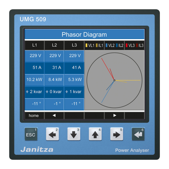
UMG 509 Applying the measuring-circuit voltage The UMG 509 is designed for the connection of .. /1A and .. /5A current transformers. Only AC currents can be measured via the current measurement inputs - DC currents cannot. Short circuit all current transformer outputs except for one. - Page 85 UMG 509 Phasor diagram, example 1 Predominantly ohmic load. Voltage current only have a minor deviation in the phase length. • The current measurement input is assigned to the correct voltage measurement input. Phasor diagram, example 2 Predominantly ohmic load.
-
Page 86: Applying The Residual Current
DC currents. applied or a fixed frequency should be set. Bearing in mind the current transformer ratio, the residual current displayed by the UMG 509 must correspond with It is not necessary to configure a the input current. - Page 87 UMG 509 Alarm status for I5, I6 Using bit-by-bit coding inside the alarm register (addr. Warning: The residual current has exceeded 19224 for I5, 19225 for I6), it is possible to read out the set warning limit value different alarm statuses:...
-
Page 88: Checking The Power Measurement
Short-circuit all current transformer outputs except for one and check the displayed power outputs. The UMG 509 may only display one power output in the phase with a non-short-circuited current transformer input. If this is not the case, check the connection of the measured voltage and the measuring-circuit current. -
Page 89: Measurement Range Exceeded (Overload)
UMG 509 Measurement range exceeded (overload) If the measurement range is exceeded, it is displayed as long as this persists and cannot be acknowledged. The measurement range is exceeded if at least one of the four voltage or current measurement inputs lies outside their specified measuring range. -
Page 90: Rs485 Interface
RS485 interface can be used to access the data Data bits: from the parameter and the measured value lists (see Parity: None RS485 configuration). Stop bits (UMG 509): External stop bits: 1 or 2 Modbus functions (master) 01 Read coil status Number format:... - Page 91 The L1-N voltage is saved in the measured value list at address 19000. The L1-N voltage is available in the FLOAT format. Address = 01 is approved as the UMG 509 device address. The Query Message appears as follows: Name...
-
Page 92: Profibus
PLC. A Profibus profile can: • retrieve measured values from the UMG, The device master file for the UMG 509 has the file name • set the digital outputs in the UMG, "U5090F15.GSD" and is included on the data carrier •... - Page 93 Fetch measured values for this profile number. PLC process output box Profile number 1. Byte = Profile number (0 to 15) 2. Byte = Data to the UMG 509 • • Profibus PLC process input box 1. Byte = Return signal from the profile number Profile number Measured values 2.
- Page 94 UMG 509 Factory pre-configured profiles Profibus profile number 0 Profibus profile number 1 Byte Value type Value Scaling Byte Value type Value Scaling index format index format Voltage L1-N Float Voltage L1-N Float Voltage L2-N Float Voltage L2-N Float Voltage L3-N...
- Page 95 UMG 509 Profibus profile number 2 Profibus profile number 3 Byte Value type Value Scaling Byte Value type Value Scaling index format index format Active energy sum L1-L3 Float Effective power L1 Float Rel. Active energy sum L1-L3 Float Effective power L2 Float Deliv.
-
Page 96: Digital In-/Outputs
UMG 509 Digital in-/outputs The UMG 509 has two digital outputs and two digital inputs. The inputs and outputs can be configured using the GridVis software (included in the scope of delivery). The settings of the functions in the configuration menu must be made using the GridVis software. - Page 97 UMG 509 Pulse output The digital outputs can be used for the output of pulses for the computation of power consumption. For this purpose, a pulse of defined length is applied on the output after reaching a certain, adjustable amount of power.
- Page 98 UMG 509 Pulse length The pulse length applies to both pulse outputs and is set The values in the table are based on the minimum pulse using the GridVis software. length and the minimum pulse interval for the maximum number of pulses per hour.
- Page 99 UMG 509 Pulse value The pulse value is used to indicate how much power (Wh or varh) should correspond to a pulse. The pulse value is determined by the maximum connected load and the maximum number of pulses per hour.
- Page 100 Set the pulse length in accordance with the requirements supply voltage of the connected pulse receiver. 24V DC At a pulse length of 30 ms, for example, the UMG 509 UMG 509 generates a maximum number of 60,000 pulses Switch and pulse outputs (see Table "maximum number of pulses"...
- Page 101 UMG 509...
-
Page 102: Service And Maintenance
Calibration intervals Disposal recommend having device recalibrated The UMG 509 can be reused or recycled as electronic by the manufacturer or an accredited laboratory every scrap in accordance with the legal provisions. 5 years approximately. permanently installed lithium... -
Page 103: Firmware Update
UMG 509 Firmware update Battery If the device is connected to a computer via Ethernet, The internal clock is fed from the supply voltage. then the device firmware can be updated via the GridVis If the supply voltage fails then the clock is powered by the software. - Page 104 UMG 509 Procedure in the event of faults Possible fault Cause Remedy No display External fuse for the power supply voltage has Replace fuse. tripped. No current display Measured voltage Connect the measured voltage. is not connected. Measurement current is not connected.
- Page 105 UMG 509 Possible fault Cause Remedy Effective power too large or too The programmed CT ratio is incorrect. Read out and program the CT ratio at the current small. transformer The current path is assigned to the wrong Check connection and correct if necessary.
-
Page 106: Technical Data
Ambient conditions during operation The UMG 509 is intended for weather-protected, stationary use. The UMG 509 must be connected to the protective current connection! Protection class I in acc. with IEC 60536 (VDE 0106, Part 1). Working temperature range K55 (-10°C - +55°C) - Page 107 UMG 509 Supply voltage Installations of overvoltage category Protection of the supply voltage (fuse) 6A, type C (approved i.a.w. UL/IEC) 230 V option: - Nominal range 95V to 240V (45-65Hz) or DC 80V .. 300V - Operating range +-10% of nominal range - Power consumption max.
- Page 108 - Resolution 0.001Hz The UMG 509 can only determine measured values, if at least a voltage L-N greater than 10Veff or a voltage L-L of greater than 18Veff is present at one voltage measurement input. Terminal connection capacity (voltage and current measurement) Connectable conductors.
- Page 109 UMG 509 Residual current monitoring (RCM) Rated current 30mA Metering range 0 to 40mA Triggering current 100µA Resolution 1µA Crest factor 1.414 (related to 40mA) Burden 4 Ohm Overload for 1 sec. Sustained overload Overload for 20 ms Residual current monitoring i.a.w.
- Page 110 UMG 509 Thermistor input 3-wire measurement Update time 1 second Connectable sensors PT100, PT1000, KTY83, KTY84 Total burden (sensor + cable) max. 4 kOhm Cable length up to 30m unshielded, from 30m shielded Sensor type Temperature range Resistor range Measurement uncertainty KTY83 -55°C to +175°C...
- Page 111 UMG 509 Digital inputs 2 Digital inputs with a joint earth Maximum counter frequency 20Hz Response time (Jasic program) 200ms Input signal present 18V to 28V DC (typical 4mA) Input signal not present 0 to 5V DC, current less than 0.5mA...
- Page 112 UMG 509 RS485 interface 3-wire connection with GND, A, B Protocol Modbus RTU/slave, Modbus RTU/master, Modbus RTU /Gateway Transmission rate 9.6kbps, 19.2kbps, 38.4kbps, 57.6 kbps, 115.2kbps, 921.6kbps Termination resistor Can be activated by micro switch Profibus interface Connection SUB D 9-pole...
- Page 113 UMG 509...
-
Page 114: Function Parameters
UMG 509 Function parameters • Measurement via current transformer ../5A • Measurements with 50/60 Hz Function Symbol Precision class Metering range Display range Total effective power (IEC61557-12) 0 to 15.3kW 0 W to 9999 GW * Total reactive power , Qv (IEC61557-12) 0 to 15.3 kvar... - Page 115 UMG 509 THD of the voltage THDu (IEC61557-12) up to 2.5 kHz 0% to 999 % THD of the voltage THD-Ru (IEC61557-12) up to 2.5 kHz 0% to 999 % Current harmonics Cl. 1 (IEC61000-4-7) up to 2.5 kHz 0 A to 9999 kA...
-
Page 116: Declaration Of Conformity
UMG 509 Declaration of conformity The product fulfils the following EC Directives: 2004/108/EC Electromagnetic compatibility of equipment. 2006/95/EC Electrical equipment for use within certain voltage limits. Standards taken into consideration: Immunity from interference IEC/EN 61326-1:2013 Class A: Industrial area IEC/EN 61000-4-2:2009... - Page 117 UMG 509...
-
Page 118: Dimension Diagrams
UMG 509 Dimension diagrams +0.8 +0.8 Cut-out size: 138 x 138 Rear side Patch cable... - Page 119 UMG 509 Side view View from below...
-
Page 120: Configuration Menu Overview
UMG 509 Configuration menu overview Additional main values Display Display Display Communication Home Voltage L-N (Measured value Status Additional main values overview) (config) Configuration Language, communication, measurement, system Display, colours, extensions Communication Measurement Display System Colours Extensions Ethernet Measuring transducer... -
Page 121: Measured Value Displays Overview
UMG 509 Measured value displays overview Main values Device name Voltage Current Effective power Overview L1 to L4 Power L1 to L3 Overview Measured (Effective power) (Tariff 1, tariff 2) values (config) Configuration Voltage Current Reactive power Reactive power Overview... - Page 122 UMG 509 Main values Effective power Harmonic Voltage Transients Events Monthly values progression L1 1 to 8 1 to 8 (L2, L3, L4) (9 to 16) (9 to 16) Bar diagram Voltage L1 (L2, L3, L4) Apparent power Harmonic Current...
- Page 123 UMG 509 Main values Phasor Oscilloscope Communication diagram status Oscilloscope Oscilloscope ULN1 to 3 ULN1 to 4 Oscilloscope IL1 to 3 IL1 to 4...
-
Page 124: Connection Example
UMG 509 Connection example PT100 DIFF 0-30 9 10 11 12 13 14 15 16 Switch RS485 Temp. Digital Digital Outputs Inputs UMG 509 Hilfsenergie Strommessung 1-4 Spannungsmessung 1-4 Auxiliary Supply Current Input 1-4 Voltage Input 1-4 L/+ N/- 19 20...
Need help?
Do you have a question about the UMG 509 and is the answer not in the manual?
Questions and answers