Table of Contents
Advertisement
Quick Links
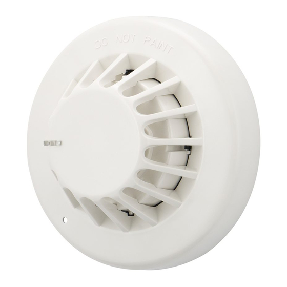
Sounder Base ULCAS380, ULMAS850, ULFXN538LBS
Installation Instructions
Model No.
Brand
ULCAS380
Eaton Cooper
ULMAS850
Eaton Menvier
ULFXN538LBS
Eaton JSB
Installation
1. Fit the box in position using the mounting details below.
2. Connect the unit according to the diagram below.
3. Recommended Loop Cable Type: FIRETUF , FP200
1. Mounting Base
I.
Knock-out the required fixing holes.
II. Fix to mounting surface using two suitable screws
If the base deforms on an uneven surface. Loosen the screws or
move to a more flat position.
50
When used with a detector, the installation and spacing shall be
50
in accordance with the requirements for smoke detectors (NFPA
60
60
72, Chapter 17).
70
70
80
When installed with the blank cover,the installation and spacing
80
50
shall be in accordance notification appliances
60
(NFPA 72, Chapter 18.)
70
80
ø
102
ø
102
ø
102
Sounder and Cover
Sounder and Cover
Sounder and Cover
Sounder and Cover
50
60
70
80
50
60
70
80
ø
102
ø
102
ø
102
Sounder and Detector
Sounder and Detector
Sounder and Detector
Sounder and Detector
in
out
2. Sounder Assembly
Clip sounder onto base. If sounder needs to be removed use a
small screwdriver to unclip.
3. Locking Tab (optional)
Fit the locking tab into the square
hole on the shoulder.
Finish assembly as stage 5.
Remove by inserting a suitable tool
(e.g. A thin screwdriver) into the hole
in the detector or cover, then rotate
detector or cover anti-clockwise.
4. Fitting Detector or Cover
Locking tab
release hole
5. Standard Connections (see diagram overleaf)
Warning: Do NOT use high voltage tester if ANY equipment is
connected to the system.
ø
102
ø
102
All connections are Power Limited.
When the base is used with the blank cover: Multiple tone
appliances which produce the three pulse temporal pattern for
the international evacuation signal [NFPA 72 (National Fire Alarm
Code)], shall be used for evacuation use only. The base must not
be used for evacuation when used with a detector head.
Terminate the screen as a oating
joint to the rear of the base within the
No addressing of the interface is required. See control panel
N
ote:
cable termination box
operation for details.
Terminate the screen as a oating
joint to the rear of the base within the
cable termination box
Do not use this
Terminate the screen as a oating
connection
joint to the rear of the base within the
Terminate the screen as a oating
Effective April 2019
Locking tab
release hole
Locking tab
Locking tab
release hole
Sounder and Cover
release hole
Locking tab
in
out
50
60
70
80
ø
102
S+
S-
F-
Advertisement
Table of Contents

Related Manuals for Eaton ULCAS380


Summary of Contents for Eaton ULCAS380
- Page 1 Sounder Base ULCAS380, ULMAS850, ULFXN538LBS Effective April 2019 Installation Instructions Model No. Brand 2. Sounder Assembly ULCAS380 Eaton Cooper Clip sounder onto base. If sounder needs to be removed use a ULMAS850 Eaton Menvier small screwdriver to unclip. ULFXN538LBS Eaton JSB Installation 1.
- Page 2 0.1 Ohm Supervised, power limited Eaton © 2019 Eaton EMEA Headquarters All Rights Reserved Route de la Longeraie 7 Eaton is a registered trademark. Eaton Electrical Systems Ltd. 1110 Morges, Switzerland Wheatley Hall Road Eaton.eu All trademarks are property Doncaster TEL: +44 (0) 1302 321541 of their respective owners.
Need help?
Do you have a question about the ULCAS380 and is the answer not in the manual?
Questions and answers