Table of Contents
Advertisement
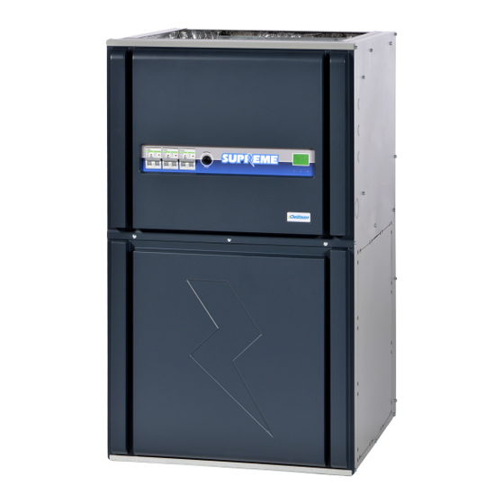
COMFORT & ADVANTAGE
INSTALLER / SERVICE TECHNICIAN:
USE THE INFORMATION IN THIS MANUAL FOR THE INSTALLATION AND
SERVICING OF THE FURNACE AND KEEP THE DOCUMENT NEAR THE UNIT
FOR FUTURE REFERENCE.
HOMEOWNER:
PLEASE KEEP THIS MANUAL NEAR THE FURNACE FOR FUTURE
REFERENCE.
Printed in Canada
Printed on 100% recycled paper
(PSC MOTOR)
Models:
Comfort
SUPXX-C120D12
SUPXX-C240D12
SUPXX-C120D20
SUPXX-C240D20
Advantage
SUPXX-A120D12
SUPXX-A240D12
SUPXX-A120D20
SUPXX-A240D20
Caution: Do not tamper with
the unit or its controls. Call a
qualified service technician.
Manufactured by :
Industries Dettson inc.
Sherbrooke, Québec - Canada
www.dettson.ca
2015-07-08
X40232 Rev. C
Advertisement
Table of Contents

Related Manuals for Dettson Supreme Comfort Series


Summary of Contents for Dettson Supreme Comfort Series
- Page 1 USE THE INFORMATION IN THIS MANUAL FOR THE INSTALLATION AND SERVICING OF THE FURNACE AND KEEP THE DOCUMENT NEAR THE UNIT Manufactured by : FOR FUTURE REFERENCE. Industries Dettson inc. HOMEOWNER: Sherbrooke, Québec - Canada PLEASE KEEP THIS MANUAL NEAR THE FURNACE FOR FUTURE www.dettson.ca...
-
Page 2: Table Of Contents
TABLE OF CONTENT 4- MAINTENANCE .......... 8 4.1- AIR FILTER ............. 8 1- SAFETY ............3 4.2- MOTOR LUBRICATION ........8 1.1- DANGER, WARNING AND CAUTION .... 3 5- FURNACE INFORMATION ......9 1.2- IMPORTANT INFORMATION ......3 1.3- DANGER OF FREEZING ........ 3 2- INSTALLATION .......... -
Page 3: 1- Safety
Never block or otherwise obstruct the filter and/or 1- SAFETY return air openings; Ask the technician installing your furnace to show and 1.1- DANGER, WARNING AND CAUTION explain to you the following items: The main disconnect switch or circuit breaker; The words DANGER, WARNING and CAUTION are used to The air filter and how to change it (check monthly identify the levels of seriousness of certain hazards. -
Page 4: Positioning The Furnace
The unit requires a 120/240 - 208 VAC power supply to the Figure 1: Upflow installation control panel, thermostat hook-up as shown on the wiring diagram. 2.1- POSITIONING THE FURNACE WARNING Fire and explosion hazard. The furnace must be installed in a level position, never where it will slope toward the front. -
Page 5: Model Over 27Kw
120/240 - 208 voltage. Models using a 120V motor require a 3- 2.5- INSTALLATION OF THE THERMOSTAT wire power supply plus an uninterrupted ground. A thermostat must be installed to control the temperature of the area to be heated. Follow the instructions supplied with the WARNING thermostat. -
Page 6: Anticipator Adjustment (If Required) On Thermostat Equipped With Heat Anticipator Adjustment
Figure 8: 1-stage thermostat, electric heating and cooling Insulate the ducts that lead through non-heated areas. Use application flexible supply and return air connectors to avoid the transmission of vibration. To make the unit run even quieter, the installer should: Use two elbows between each outlet and the supply and return air plenum;... -
Page 7: Installation Of Accessories
2.7- INSTALLATION OF ACCESSORIES 3.2- USE OF MANUAL FURNACE CONTROLS When there is a demand for heat, the pilot light (L-1) comes on. WARNING Refer to the wiring diagram. Electrical shock hazard. When the “HI/LO” switch is put into the “LO” position, it will shut down approximately half the elements. -
Page 8: Cooling Mode
3.3.2- Cooling mode The thermostat closes the R-G circuit, thereby activating the CAUTION 24 VAC relay. The blower starts up to cooling speed. It is important to check the airflow and to ascertain that the The thermostat closes the R-Y contact, thereby activating the compressor relay of the air conditioner. -
Page 9: 5- Furnace Information
5- FURNACE INFORMATION Model: Serial number: Furnace installation date: Service telephone # - Day: Night: Dealer name and address: START-UP RESULTS Voltage: Total current consumed by the elements: Supply air temperature: Return air temperature: Supply air duct static pressure: Return air duct static pressure: Total pressure: Calculated air flow: Current consumed by the blower motor:... -
Page 10: Table 2: Technical Specifications
Table 2: Technical specifications SUPxx-x120D12 SUPxx-x120D20 RATINGS AND PERFORM ANCE 1/3 HP / 120V M otor 1 HP / 120V M otor Capacity Power, total @ 240V / 208V (Kw) 10 / 7.5 15 / 11.3 18 / 13.5 20 /15 23 / 17.3 25 / 18.8 20 /15... -
Page 11: Table 3: Airflow (Cfm) - Supreme
Table 3: Airflow (CFM) - S with 1/3HP motor UPREME SUPREME equipped with a 1/3 HP / 120V blower motor Blower External static pressure (inche of W.C.) speed MED-LOW MED-HIGH 1 025 1 010 HIGH 1 260 1 240 1 200 1 150 1 110 1 055... -
Page 12: Comfort Psc
Figure 12 : Electrical diagram, S Comfort PSC UPREME... - Page 13 Figure 13 : Electrical diagram, S Advantage PSC UPREME...
-
Page 14: Comfort
Figure 14: Parts list, S Comfort PSC UPREME... -
Page 15: Upreme Upreme
Table 5: Parts list, S Comfort PSC UPREME Item Description Comments B04431 Acoustic insulation B04343-03 Left side panel assembly Left panel, items 3 and 1 included B04340-02 Left side panel insulation B04344-01 Back panel assembly B04341 Top back panel insulation B04343-01 Right side panel assembly Right panel, items 7 and 1 included... -
Page 16: Advantage
Figure 15: Parts list, S Advantage PSC UPREME... -
Page 17: Upreme Upreme
B04296 Electrical sequencer kit Supreme 15kw B04297 Electrical sequencer kit Supreme 10kw B04275 Top door X50042 Label logo Dettson B04349 Bottom door assembly B04356-03 Blower assembly 1hp (120v-PSC) Supreme 20/23/25/27/30 kw B04356-01 Blower assembly 1/3hp (120v-PSC) Supreme 10/15/18/20/23/25 kw B04356-02...
Need help?
Do you have a question about the Supreme Comfort Series and is the answer not in the manual?
Questions and answers