Table of Contents
Advertisement
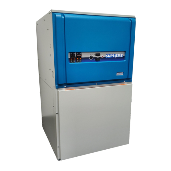
INSTALLATION INSTRUCTIONS AND HOMEOWNER'S
ADVANTAGE
(ECM MOTOR)
MULTI-POSITION
INSTALLER / SERVICE TECHNICIAN:
USE THE INFORMATION IN THIS MANUAL FOR THE IN-
STALLATION AND SERVICING OF THE FURNACE AND
KEEP THE DOCUMENT NEAR THE UNIT FOR FUTURE
REFERENCE.
HOMEOWNER:
PLEASE KEEP THIS MANUAL NEAR THE FURNACE FOR
FUTURE REFERENCE.
Printed in Canada on
100% recycled paper
MANUAL: ELECTRIC FURNACE
Models:
SUPXX-A240V20
SUPXX-A240V12
Attention:
Do not tamper with the unit or its controls.
Call a qualified service technician.
Manufactured by: Dettson Industries Inc.
Sherbrooke,
www.dettson.com
2022-03-28
Qc,
Canada
X40233 Rev.H
Advertisement
Table of Contents

Subscribe to Our Youtube Channel
Related Manuals for Dettson SUPREME SUP A240V20 Series


Summary of Contents for Dettson SUPREME SUP A240V20 Series
- Page 1 Do not tamper with the unit or its controls. KEEP THE DOCUMENT NEAR THE UNIT FOR FUTURE Call a qualified service technician. REFERENCE. HOMEOWNER: Manufactured by: Dettson Industries Inc. PLEASE KEEP THIS MANUAL NEAR THE FURNACE FOR Sherbrooke, Canada FUTURE REFERENCE.
-
Page 2: Table Of Contents
3.4 AIRFLOW VERIFICATION ......3.4.1 Supply Air Temperature Rise Test ..3.4.2 High limit verification . -
Page 3: Safety
b) Do not use this furnace if any part of it was under water. Call a qualified service technician immedi- SAFETY ately to assess the damage and to replace all criti- cal parts that were in contact with water; 1.1 DANGER, WARNING AND CAUTION c) Do not store gasoline or any other flammable sub- stances, such as paper or carton, near the furnace;... -
Page 4: Installation
2.3 CONFIGURATIONS b) Ask someone to frequently check the house during the cold weather season to make sure that there is This furnace requires suitable ductwork. sufficient heat to prevent the pipes from freezing. Tell this person to call an emergency number if re- 2.3.1 Upflow installation quired. -
Page 5: Suspended Installation
either suspended or on a combustible floor with a choice In the event that wires inside the unit require replace- of right or left discharge, the clearances from combustible ment, these must be copper wires only with same tem- material must be adhered to. Refer to Figure 3 for addi- perature rating and sizes as originals. -
Page 6: Anticipator Adjustment (If Required) On Thermostat Equipped With Heat Anticipator Adjustment
Figure 8: 2-stage heating & 1-stage air conditioning & heat pump thermostat Figure 5: 1-stage thermostat, electric heating only Figure 9: 2-stage heating & 2-stage air conditioning & heat pump thermostat + dehumidification mode 2.5.1 Anticipator adjustment (if required) on thermostat equipped with heat anticipator adjustment Some thermostats are equipped with a heat anticipator that must be adjusted according to the instructions sup-... -
Page 7: Supply Air Adjustments
Refer to the applicable local and/or national installation codes. Insulate the ducts that lead through non-heated areas. Use flexible supply and return air connectors to avoid the transmission of vibration. To make the unit run even quieter, the installer should: 1. -
Page 8: Ac/Hp Cfm Adjust
4. ENH: enhanced selection provides a 30 second ON delay with no airflow followed by 150 seconds at 1. AC – Air Conditioner provides approximately 400 70% airflow, and no OFF delay for added comfort. CFM per ton for greater efficiency and humidity This profile will minimize cold blow in heat pump control with the AC/HP CFM ADJUST set to the operation and could enhance system efficiency. -
Page 9: Installation Of Accessories
2.7.3 Dehumidify capability with standard 2.7 INSTALLATION OF humidistat connection ACCESSORIES Latent capacities for systems using this unit are bet- ter than average systems. If increased latent capacity is an application requirement, the field wiring terminal block WARNING provides a connection terminal (DH) for use of a standard humidistat. -
Page 10: Operating Sequence
3.3.3 Cooling mode - two stage “HI” position during the winter months to ensure ad- equate heating. • First stage (low) cooling: Thermostat closes cir- Also, this switch must remain in the “HI” position when a cuits R to G, R to O, and R to Y1. 2-stage or outdoor thermostat is used to control the elec- Furnace delivers low stage cooling airflow. -
Page 11: Airflow Verification
3.3.8 Heat pump heating mode – 4. Calculate the temperature rise by subtracting the return air temperature from the supply air tempera- Modulating thermostat, outdoor unit ture. two stage • First stage (low) heating: Thermostat closes cir- If the temperature rise exceeds the temperature spec- cuits R to G and R to Y1. -
Page 12: Air Filter
4.1 AIR FILTER 4. Set the thermostat higher than room temperature. If the unit does not start up, cut the power and call The disposable filter should be replaced twice a year. a qualified service technician. The presence of animal hair, dust, etc. may necessitate more frequent changes. -
Page 13: Sequence Of Operation
6 SEQUENCE OF OPERATION Table 1: Sequence of operation Thermostat to Control Mode Control Control Function Board 24 VAC Electric Heat only Continous Fan Fan ON at the selected continous fan CFM (Fan switch ON) Fan OFF Fan ON at 50% of the selected Heat CFM, 1st stage of Heat ON** Thermostat calls for 1st stage Heat 1st stage of Heat OFF, Fan OFF Fan ON at selected Heat CFM, 1st stage &... - Page 14 Thermostat to Control Mode Control Control Function Board 24 VAC Compressor ON, Fan ON after delays at selected Heat Pump CFM Thermostat calls for 1st stage Heat (Heat pump heating mode) Y/Y2 & G Compressor OFF, Fan OFF after selected Heat Pump delays Fan ON at selected Heat CFM, 1st stage &...
-
Page 15: Table
7 TECHNICAL SPECIFICATIONS Table 2: Technical specifications(240V) RATING AND SUPxx-A240V12 SUPxx-A240V20 PERFORMANCE Motor 1/2 HP / 240V Motor 1 HP / 240V Capacity Power, total @ 240V / 208V (Kw) 10 / 7.5 15 / 11.3 18 / 13.5 20 /15 23 / 17.3 25 / 18.8 20 /15 23 / 17.3 25 / 18.8 27 / 20.3 30 / 22.5... -
Page 16: Figure 15: Furnace Dimensions
REVISIONS REV. DESCRIPTION DATE Figure 15: Furnace Dimensions 559mm 22" 25mm 1" SUPPLY 25mm ALIMENTATION 1" Identical on the 2 sides Identique sur les 2 cotés 559mm 22" 927mm 508mm x 508mm 36 1/2" 20" x 20" Identical on the 2 sides, the back and below. -
Page 17: Table
Table 3: Airflow tables SUPREME Advantage ECM ½ HP motor COOLING OR HEAT PUMP HEATING MODE (WITH HP-EFF SELECTED AC / HP SIZE A/C size AC/HP CFM ADJUST AC/HP CFM ADJUST AC/HP CFM ADJUST Adjustment (TONS) BLACK wire position BLACK wire position BLACK wire position BLUE wire position (BLK) = (NOM) -
Page 18: Table
Table 4: Airflow tables SUPREME Advantage ECM 1HP motor COOLING OR HEAT PUMP HEATING MODE (WITH HP-EFF SELECTED AC / HP SIZE A/C size AC/HP CFM ADJUST AC/HP CFM ADJUST AC/HP CFM ADJUST Adjustment (TONS) BLACK wire position BLACK wire position BLACK wire position BLUE wire position (BLK) = (NOM) -
Page 19: Venting Delays
Table 5: Venting Delays ON & OFF DELAY FOR COOLING AND HEAT PUMP HEATING MODE ON / OFF DELAY Adjustment ON-Delay OFF-Delay WHITE wire position Time % "CFM" - Time 0 / 90 0 sec. 100% - 90 sec. 30 / 90 30 sec. -
Page 20: Figure 16: Electrical Diagram, Supreme Advantage Ecm
Figure 16: Electrical diagram, S Advantage ECM UPREME... -
Page 21: Figure 17: Parts List, Supreme Advantage Ecm
Figure 17: Parts list, S Advantage ECM UPREME... -
Page 22: Parts List, Supreme Advantage Ecm
Table 6: Parts list, S Advantage ECM UPREME Item Description Comments B04343-04 Left side panel assembly Left panel, items 3 and 1 included B04344-02 Back panel assembly B04343-02 Right side panel assembly Right panel, items 7 and 1 included B04302-01 Top front panel L01J006 Breaker 60 A...
Need help?
Do you have a question about the SUPREME SUP A240V20 Series and is the answer not in the manual?
Questions and answers