Table of Contents
Advertisement
Quick Links
OBL154
OVL154
THIS BOOKLET CONTAINS
•
Copyright 2012 CAC / BDP
7310 W. Morris St.
Manufacturer reserves the right to change, at any time, specifications and design without notice and without obligation.
Installation Instructions
IMPORTANT INFORMATION
•
Indianapolis, IN 46231 Printed in canada. Edition date: 04/19
MULTIPOISE OIL FURNACE
INPUT CAPACITIES 126,000-154,000
INSTALLER: Use the informationin this booklet to
install the appliance and affix this booklet adjacent
to the appliance after installation
USER: Keep this booklet of information for future
reference
SERVICER: Use the information in this booklet to
service the appliance and affix the booklet adjacent
to the appliance after servicing
Catalog No: IM - OBL154-10/ X40172 Rev. J
Replaces: IM_OBL154_09
Advertisement
Table of Contents

Subscribe to Our Youtube Channel
Related Manuals for Dettson OBL154


Summary of Contents for Dettson OBL154
- Page 1 7310 W. Morris St. Indianapolis, IN 46231 Printed in canada. Edition date: 04/19 Catalog No: IM - OBL154-10/ X40172 Rev. J Manufacturer reserves the right to change, at any time, specifications and design without notice and without obligation. Replaces: IM_OBL154_09...
-
Page 2: Table Of Contents
Table of content SAFETY 1.1 SAFETY LABELING AND WARNING SIGNS ..........1.2 IMPORTANT INFORMATION . - Page 3 3.1 START-UP............... 13 3.2 OPERATING SEQUENCE OIL HEATING MODE .
- Page 4 List of tables Table 1: Blower speed adjustments, heating mode, 4-speed motor ..... . . Table 2: Blower speed adjustments, 4-speed motor ....... Table 3: Airflow adjustments - Heating mode .
-
Page 5: Safety
a) It is the homeowner’s responsibility to engage a qualified technician for the installation and subse- quent servicing of this furnace; SAFETY b) Do not use this furnace if any part of it was under water. Call a qualified service technician immedi- ately to assess the damage and to replace all criti- 1.1 SAFETY LABELING AND cal parts that were in contact with water;... -
Page 6: Danger Of Freezing
1.4 DANGER OF FREEZING 2.1 POSITIONING THE FURNACE WARNING CAUTION If your furnace is shut down during the cold weather IRE AND EXPLOSION HAZARD season, water pipes may freeze, burst and cause se- The furnace must be installed in a level position, rious water damage. -
Page 7: Electrical System
Figure 1 – Location and dimensions of ventilation air openings in a closet door Figure 3 – Thermostat wiring, heating and air condi- tioning with ECM variable speed motor 2.2 ELECTRICAL SYSTEM CAUTION The exterior of the unit must have an uninterrupted ground to minimize the risk of bodily harm, if ever an electrical problem develops. -
Page 8: Installation Of The Burner
marking. Figure 4 – Thermostat wiring, heating and air condi- tioning/heat pump with ECM variable speed motor 2.4.2 Air and Turbulator Settings Before starting the burner for the first time, adjust the air and turbulator settings to those listed in this manual (Table 7). -
Page 9: Factory-Built Chimneys
the chimney lining and dimensions must conform to local device itself, as well as in section 4 of this Manual. and national codes. 2.6.1 BVSO Functional Test 2.5.2 Factory-built chimneys The purpose of the following test is only to check that the Oil fired furnaces are approved for use with “L”... -
Page 10: Contaminated Combustion Air
2.7.1 Contaminated Combustion Air CAUTION Installations in certain areas or types of structures will in- When a 0,75 USGPH or smaller nozzle is used, a 10 crease the exposure to chemicals or halogens that may micron or finer filter must be installed on the oil sup- harm the furnace. -
Page 11: Supply Air Adjustments (4 Speed Motors)
2.10 SUPPLY AIR ADJUSTMENTS To effect the adjustment, the RED (for heating) and BLUE (for cooling and heat pump) wires can be changed on the (4 SPEED MOTORS) motor. Also, refer to the position of the wires on the electronic board of the unit and consult the wiring dia- On units equipped with 4-speed blower motors, the sup- grams. -
Page 12: Table 2: Blower Speed Adjustments, 4-Speed Motor
Table 2 – Blower speed adjustments, 4-speed motor RECOMMENDED A/C CAPACITY (TONS) BLOWER SPEED MED-LOW MED-HIGH HIGH... -
Page 13: Supply Air Adjustments (Ecm Variable Speed Motors)
2.11 SUPPLY AIR ADJUSTMENTS conditioning output. The start/stop delays of the blower must also be adjusted by positioning the DIP switches on (ECM VARIABLE SPEED the electronic board. MOTORS) Refer to the following tables, airflow tables and the wiring diagram in this manual for the proper settings. On units equipped with ECM variable speed blower mo- tors, the air supply must be adjusted based on heating/air Table 3 –... -
Page 14: Air Conditioner (Or Heat Pump)
the S terminal on the PSC electronic board or one of the 120 VAC terminals on the ECM electronic board can be used to provide a constant supply of 120 VAC. 3 OPERATION Also refer to the instructions supplied with the accessory. 3.1 START-UP CAUTION 2.12.3 Air Conditioner (or Heat Pump) -
Page 15: Checks And Adjustments
5) When the call for heat is satisfied, the solenoid test probe into the hole. For installation using a valve closes, the flame goes out and the burner mo- sidewall venting, use the orifice provided on the tor stops (after post purge delay, if applicable). breech plate;... -
Page 16: Supply Air Temperature Rise Test
CAUTION CAUTION Low flue gas temperature increases the risk of con- Do not attempt to start the burner when excess oil densation. Adjust the total temperature at or higher has accumulated, when the furnace is full of vapour or then 204°C (400°F) in order for the heat exchanger when the combustion chamber is hot. -
Page 17: Cleaning The Blocked Vent Shut-Off Device (Bvso)
If a cleaning is necessary, the following steps should be 6. Clean and remove any build-up or obstruction in- performed: side the heat transfer tube; 7. Re-mount, lock and fasten the control box with the 1. Turn OFF all utilities upstream from the furnace; 2 screws removed in step 4;... -
Page 18: Furnace Information
5 FURNACE INFORMATION Model: ..........Serial number: . -
Page 19: Technical Specifications
6 TECHNICAL SPECIFICATIONS Table 7 – Technical specifications 154 Lowboy Series UNITS WITH 1.0 HP 4-SP. MOTOR UNITS WITH 1.0 HP ECM MOTOR RATING AND PERFORMANCE Firing rate(USGPH)* 0.90 1.10 0.90 1.10 Input (BTU/h)* 126,000 154,000 126,000 154,000 Heating temperature rise (Degr. F)* 55 - 75 Degr. -
Page 20: Table 8: Airflow Data, Models With 1.0 Hp Ecm Motor
Table 8 – Airflow data, models with 1.0 HP ECM motor OIL HEATING MODE 24 VAC input (R) on W only SW1- HEAT HEAT INPUT CFM with SW3-ADJ CFM with SW3-ADJ CFM with SW3-ADJ DIP switch position A DIP switch position B DIP switch position C DIP switch position (USGPH) -
Page 21: Table 9: Airflow Data Model With 1.0 Hp 4-Speed Motor (Psc)
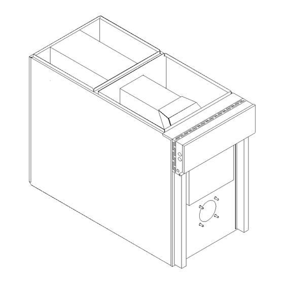
Table 9 – Airflow data model with 1.0 HP 4-speed motor (PSC) EXTERNAL STATIC PRESSURE WITH AIR FILTER BLOWER SPEED 0.2” (W.C.) 0.3” (W.C.) 0.4” (W.C.) 0.5” (W.C.) 0.6” (W.C.) 0.7” (W.C.) HIGH 2185 2115 2045 1995 1905 1820 MED-HIGH 1900 1845 1810... - Page 22 Figure 7 – Furnace Dimensions...
- Page 23 Figure 8 – Wiring diagram 4-speed motor (PSC)
- Page 24 Figure 9 – Wiring diagram variable speed motor (ECM)
- Page 25 Figure 10 – Parts list with 4-speed motor (PSC)
-
Page 26: Table 11: Parts List With 4-Speed Motor Psc
Table 11 – Parts list with 4-speed motor PSC Item Description Comments B03775 HEAT EXCHANGER ASSEMBLY Heat exchanger only B03761 FLOOR ASSEMBLY B03746 WIRE CHANNEL, INT. B03758 LOWER BLOWER DIVIDER ASSEMBLY Panel, 3 gaskets and filter rack included B03745 BAFFLE, LATERAL B03754-02 SIDE PANEL ASSEMBLY (LEFT) Panel, insulation, baffle and filter rack included... - Page 27 Figure 11 – Parts list with variable speed motor (ECM)
-
Page 28: Table 12: Parts List With Variable Speed Motor (Ecm)
Table 12 – Parts list with variable speed motor (ECM) Item Description Comments B03775 HEAT EXCHANGER ASSEMBLY Heat exchanger only B03761 FLOOR ASSEMBLY B03746 WIRE CHANNEL, INT. B03758 LOWER BLOWER DIVIDER ASSEMBLY Panel, 3 gaskets and filter rack included B03745 BAFFLE, LATERAL B03754-02 SIDE PANEL ASSEMBLY (LEFT)
Need help?
Do you have a question about the OBL154 and is the answer not in the manual?
Questions and answers