Table of Contents
Advertisement
Quick Links
Advertisement
Table of Contents

Related Manuals for Acromag VPX6600


Summary of Contents for Acromag VPX6600
- Page 1 Artisan Technology Group is your source for quality new and certified-used/pre-owned equipment SERVICE CENTER REPAIRS WE BUY USED EQUIPMENT • FAST SHIPPING AND DELIVERY Experienced engineers and technicians on staff Sell your excess, underutilized, and idle used equipment at our full-service, in-house repair center We also offer credit for buy-backs and trade-ins •...
- Page 2 6th Generation Core 3U VPX CPU Module USER’S MANUAL ACROMAG INCORPORATED 30765 South Wixom Road Wixom, MI 48393-2417 U.S.A. Tel: (248) 295-0310 Email: solutions@acromag.com Copyright 2019, Acromag, Inc., Printed in the USA. Data and specifications are subject to change without notice. 8501096E...
-
Page 3: Table Of Contents
3.1.3 Core Configuration Switch SW3 ...................... 18 3.2 Power Supply and Management ................. 19 3.2.1 Power Supply Requirements ......................19 3.2.2 Programmable CPU Power Limits ....................19 3.2.3 Power Management ........................20 Acromag, Inc. Tel: 248-295-0310 - 1 - - 1 - https://www.acromag.com http://www.acromag.com... - Page 4 3.13.1 Trusted Platform Support ......................28 3.13.2 Password Control .......................... 29 3.14 System Management ....................29 ® 3.14.1 Intel Hyper-Threading Technology ....................29 ® 3.14.2 Enhanced Intel SpeedStep Technology (EIST) ................29 Acromag, Inc. Tel: 248-295-0310 - 2 - - 2 - https://www.acromag.com http://www.acromag.com...
- Page 5 3.17.2 Expansion Plane ..........................34 3.17.3 Control Plane..........................34 4.0 BIOS INFORMATION AND CONFIGURATION ............. 35 4.1 VPX6600 Special BIOS Features ................... 35 4.2 Drivers and Utilities ....................35 5.0 SERVICE AND REPAIR ....................36 5.1 Service and Repair Assistance ..................36 5.2 Preliminary Service Procedure ..................
- Page 6 6.5 Reliability Prediction ....................42 6.6 Installation of M.2 Expansion Card and Battery Replacement ........42 6.6.1 VPX6600-LF (Air-Cooled) M.2 Expansion Card Installation ............. 42 6.6.2 VPX6600-LF (Air-Cooled) Battery Replacement ................45 6.6.3 VPX6600-CC-LF (Conduction-Cooled) M.2 Expansion Card Installation .......... 47 6.6.4 VPX6600-CC-LF (Conduction-Cooled) Battery Replacement............
- Page 7 7.4.2 Relative Humidity ..........................63 7.4.3 Vibration and Shock Standards ....................... 63 7.4.4 EMC Directives ..........................63 7.5 Reliability Prediction ....................64 7.6 Certificate of Volatility ....................65 REVISION HISTORY ......................66 Acromag, Inc. Tel: 248-295-0310 - 5 - - 5 - https://www.acromag.com http://www.acromag.com...
-
Page 8: General Information
1.1 Intended Audience This users’ manual was written for technically qualified personnel who will be working with I/O devices using the VPX6600 CPU. It is not intended for a general, non-technical audience that is unfamiliar with computer-on-module (COM) devices and their application. -
Page 9: Product Summary
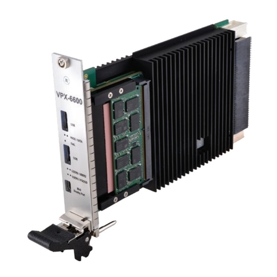
USER’S MANUAL VPX6600 1.3 Product Summary The VPX6600 is a CPU module that uses an Intel 6 Generation Core Processor (Skylake) with a 3U VPX form factor. It is available in both air and conduction-cooled varieties. The module can support either one or two DDR4 ECC SODIMMs, for a total of up to 32GB. -
Page 10: Related Material
Conduction-cooled 3U VPX CPU Module VPX6601-CC-LF -40°C to 85°C (No Battery) VPX6600-RTM-LF VPX6600 Rear Transition Module -40°C to 85°C Note: All VPX6600 CPU modules contain 32GB of DDR4 SDRAM memory. Acromag, Inc. Tel: 248-295-0310 - 8 - - 8 - https://www.acromag.com http://www.acromag.com... -
Page 11: Key Components And Features
USER’S MANUAL VPX6600 1.6 Key Components and Features The VPX6600 block diagram shown in Fig. 1.6.1 illustrates the key components and features that are summarized on the following pages. Figure 1.6.1: VPX6600 Block Diagram 1.6.1 Intel® 6th Gen (Skylake) Xeon CPU The VPX6600 uses the 2.8GHz (3.7GHz max Turbo) quad-core Intel 6th Gen... -
Page 12: Intel Cm236 Pch
The fourth is connected to the M.2 expansion slot. • SATA Gen3 (7) – There are seven SATA III ports on the VPX6600. All the ports are configurable as SATA ports or PCIe lanes. Two are connected to the P2 backplane connector. One is connected to the M.2 expansion site. -
Page 13: Intel I350 Quad Gigabit Ethernet Controller
The Avago PEX8714 is a 12-lane, 5-port PCI Express Gen 3 switch. The VPX6600 uses the switch to interface with the PCIe x4 Data Plane fat pipe connection on the VPX backplane. The switch is used on the VPX6600 to allow it to be used in multi-processor systems that do not contain a dedicated PCIe switch card. -
Page 14: Preparation For Use
It is important that the user employ satisfactory overall system design. It is understood and agreed by the Buyer and Acromag that this is the Buyer's responsibility. WARNING: This board utilizes static sensitive components and should only be handled at a static-safe workstation. -
Page 15: Installing Into A Vpx Backplane
2. Verify that all DIP switch settings are correct. 3. Verify that the card cage slot is clear and accessible. 4. Install the VPX6600 in the card cage by centering the unit on the guides in the slots (P0 connector facing up). Push the board slowly toward the rear of the chassis until the VPX connectors engage. -
Page 16: Hardware Information And Configuration
USER’S MANUAL VPX6600 3.0 HARDWARE INFORMATION AND CONFIGURATION Figure 3.1.1: VPX6600 Top View (right) Bottom View (left) Acromag, Inc. Tel: 248-295-0310 - 14 - - 14 - https://www.acromag.com http://www.acromag.com... -
Page 17: Module Hardware Switch Configuration
The configuration switch settings for SW1 depends on the revision of the board. If the revision of the VPX6600 product is Rev G or earlier, use the SW1 switch settings shown in Table 3.1.a. If the revision of the VPX6600 product is Rev H or later, use the SW1 switch settings shown in Table 3.1.b. - Page 18 USER’S MANUAL VPX6600 Table 3.1.b summarizes the functions, settings, and descriptions for dip switches SW1-1 thru SW1-4 for Rev H or later VPX6600 products. Table 3.1.b: Core Configuration Switch SW1 Core Switch Setting Position Function Description Configuration SW1-1 SW1-2 Switch SW1...
-
Page 19: Core Configuration Switch Sw2
FRU EEPROM FRU Temperature Sensor When configured to use the auxiliary +3.3V supply, these devices can still be operated while the rest of the system is unpowered. Acromag, Inc. Tel: 248-295-0310 - 17 - - 17 - https://www.acromag.com http://www.acromag.com... -
Page 20: Core Configuration Switch Sw3
SW3-2 is reserved and should be left in the OFF position for normal operation. SW3-3 is reserved and should be left in the OFF position for normal operation. SW3-4 is reserved and should be left in the OFF position for normal operation. Acromag, Inc. Tel: 248-295-0310 - 18 - - 18 - https://www.acromag.com... -
Page 21: Power Supply And Management
USER’S MANUAL VPX6600 3.2 Power Supply and Management 3.2.1 Power Supply Requirements The VPX6600 must be supplied both +3.3V and 5V from the VPX backplane. For allowed voltage ranges and expected power draw, see the specifications listed Section 6.4. 3.2.2 Programmable CPU Power Limits The VPX6600 features programmable power limits, allowing the user to 'dial-down' the maximum power consumption of the CPU in systems where power is a concern. -
Page 22: Power Management
Aptio Skylake Core BIOS Manual. 3.3 CPU The VPX6600 uses the 2.8GHz (3.7GHz max Turbo) quad-core Intel 6th Gen (Skylake) Xeon E3-1505Mv5 CPU. This is a 64-bit CPU using a 14-nanometer process with integrated GT2 graphics and contains direct interfaces for DDR4, DDI, and PCIe x16. -
Page 23: Active Processor Core Selection
The fourth is connected to the M.2 expansion slot. • SATA Gen3 (7) – There are seven SATA III ports on the VPX6600. All the ports are configurable as SATA ports or PCIe lanes. Two are connected to the P2 backplane connector. -
Page 24: System Memory
DIMMs, the VPX backplane, the Ethernet controller, and an on-board EEPROM that can be used for module identification. 3.5 System Memory The VPX6600 CPU module has two 260‐pin, right‐angle SODIMM sockets to accept DDR4 ECC SDRAM modules. At least one SDRAM module is required to make the system operational. -
Page 25: Displayport
AC coupled and need level shifting to convert the AC coupled signals to the HDMI compliant digital signals. The Intel 6 Gen Skylake Core CPU is designed in accordance with the High- Definition Multimedia Interface Specification Version 1.4. Acromag, Inc. Tel: 248-295-0310 - 23 - - 23 - https://www.acromag.com http://www.acromag.com... -
Page 26: Integrated Audio
The displays can support different refresh rates, resolutions, and color depth. 3.6.5 Multi-Stream Transport The VPX6600 module supports Multi-Stream Transport (MST), enabling multiple monitors to be used via a single DisplayPort connector. The max MST DP supported resolution is:... -
Page 27: Intel ® High Definition Audio
3.9 Flexible I/O There are 7 lanes on the VPX6600 that can be configured as either PCIe lanes or as SATA ports. The two ports on the P2 VPX backplane connector are hard- wired to be SATA ports. The lanes going to the M.2 connector are configured by the storage module that is installed. -
Page 28: General I/O
3.10 General I/O 3.10.1 General Purpose I/O (GPIO) The VPX6600 supports 6 GPIO pins which are directly connected to the PCH's GPIO pins. The direction is software configurable. The GPIO pins are available on the P2 VPX backplane connector. The GPIO pins are 3.3V level signals. -
Page 29: Serial Ports
• USB debug capability on any USB 3.0-capable port Two of the USB 3.0 ports are available via the front panel of the VPX6600 for air-cooled models only. The remaining 2 USB 3.0 ports and the two USB 2.0 ports are routed to the P2 VPX backplane connector. -
Page 30: Gigabit Ethernet
USER’S MANUAL VPX6600 3.11 Gigabit Ethernet The VPX6600 uses the Intel i350 Quad Gigabit Ethernet Controller, which contains both the media access control (MAC) and the physical layer (PHY) for each port. The VPX6600 provides three Gigabit Ethernet ports configured as follows: •... -
Page 31: Password Control
(Intel VT-x) added hardware support in the processor to improve the virtualization performance and robustness. The second revision of this specification (Intel VT-d) adds chipset hardware implementation to improve I/O performance and robustness. Acromag, Inc. Tel: 248-295-0310 - 29 - - 29 - https://www.acromag.com... -
Page 32: Intel ® Trusted Execution Technology (Txt)
Acromag, Inc. Tel: 248-295-0310 - 30 - - 30 - https://www.acromag.com... -
Page 33: Intel ® Active Management Technology
The temperature of the Intel® CM236 PCH is monitored by two thermal sensors located on the PCH. The system will be shut down by the PCH when its thermal limit is reached. Acromag, Inc. Tel: 248-295-0310 - 31 - - 31 - https://www.acromag.com... -
Page 34: Thermal Monitoring
For further information on configuring the memory bandwidth throttling based on temperature readings from the DIMM’s thermal sensor, refer to Aptio Skylake Core BIOS Manual. Acromag, Inc. Tel: 248-295-0310 - 32 - - 32 - https://www.acromag.com... -
Page 35: Watchdog
For further information on the Watchdog feature, refer to Aptio Skylake Core BIOS Manual. 3.17 VPX Profile The VPX6600 is designed to be used in OpenVPX module profile MOD3-PAY- 1F2F2U-16.2.2-4. This module profile complies with OpenVPX slot profile SLT3- PAY-1F2F2U-14.2.2 shown in Figure 3.17.a below. -
Page 36: Data Plane
The VPX6600 uses the Avago PEX8714 PCIe switch for its Data Plane connection. The PCIe switch supports non-transparent bridging which allows the VPX6600 to be used in multi-processor VPX systems that do not contain a dedicated switch card. 3.17.2 Expansion Plane The VPX6600 provides two PCIe fat pipe interfaces to be used as Expansion Plane connections to adjacent slots in the system. -
Page 37: Bios Information And Configuration
Select COMx Mode - Sets the corresponding COM port protocol to RS-232 or RS-422/485. The default is RS-232. 4.2 Drivers and Utilities Drivers and Utilities for the VPX6600 can be downloaded from Acromag's website at https://www.acromag.com/. Acromag, Inc. Tel: 248-295-0310... -
Page 38: Service And Repair
5.3 Where to Get Help If the problem persists, the next step should be to visit the Acromag worldwide web site at https://www.acromag.com/. Our web site contains the most up-to-date product and software information. -
Page 39: Specifications
USER’S MANUAL VPX6600 6.0 SPECIFICATIONS 6.1 Physical The VPX6600 is a 3U VPX module that conforms to the 1" backplane spacing set forth by the VITA 48 specification (both air and conduction models). Depth 95.0 mm (3.740 in) Width 125.0 mm (4.921 in) PCB Thickness 1.68 mm (0.066 in) -
Page 40: P2 Vpx Connector
There are two USB 3.0 connectors and one Mini-DisplayPort connector located on the front panel of the VPX6600. Using these connectors, along with an on-board bootable M.2 storage device, the VPX6600 can be operated without the need for a Rear Transition Module. -
Page 41: J7 Usb 3.0 Connector
This standard 20-pin Mini-DisplayPort connector (TE Connectivity – 2129320) brings DisplayPort D out to the front panel. SIGNAL DPC_HPD DPC_TX0_P DPC_AUX_SEL DPC_TX0_N DPC_TX1_P DPC_TX3_P DPC_TX1_N DPC_TX3_N DPC_TX2_P DPC_CTRL_AUX_P DPC_TX2_N DPC_CTRL_AUX_N +3.3V Acromag, Inc. Tel: 248-295-0310 - 39 - - 39 - https://www.acromag.com http://www.acromag.com... -
Page 42: Power Requirements
USER’S MANUAL VPX6600 6.3 Power Requirements The VPX6600 requires +3.3V and +5V from the VPX backplane. The +/- 12V supplies are not used. Additionally, the switch SW2 can be used to configure certain devices to use the auxiliary +3.3V_AUX supply. -
Page 43: Relative Humidity
Shock, Operating: Designed to comply with IEC 60068-2-27: 30G, 11ms half sine, 50G, 3mS half sine, 18 shocks at 6 orientations for both test levels 6.4.4 EMC Directives The VPX6600 is designed to comply with EMC Directive 2004/108/EC. • Immunity per EN 61000-6-2: Electrostatic Discharge Immunity (ESD), per IEC 61000-4-2. -
Page 44: Reliability Prediction
FIT is Failures in 10 hours. 6.6 Installation of M.2 Expansion Card and Battery Replacement 6.6.1 VPX6600-LF (Air-Cooled) M.2 Expansion Card Installation 1. Remove the 8 screws (M2 x 6mm) that secure the heatsink to the board. Remove the heatsink. - Page 45 3. Install the M.2 expansion card into socket. 4. Place the washer on the VPX board and carefully press down the M.2 expansion card and secure with shoulder screw. Acromag, Inc. Tel: 248-295-0310 - 43 - - 43 - https://www.acromag.com...
- Page 46 VPX6600 Note: The washer should be under the M.2 expansion card as shown below. 5. Re-install the heatsink and secure with 8 screws (M2 x 6mm) VPX6600-LF (Air-cooled) M.2 expansion card installation complete. Acromag, Inc. Tel: 248-295-0310 - 44 - - 44 - https://www.acromag.com...
-
Page 47: Vpx6600-Lf (Air-Cooled) Battery Replacement
USER’S MANUAL VPX6600 6.6.2 VPX6600-LF (Air-Cooled) Battery Replacement 1. Remove the 8 screws (M2 x 6mm) that secure the heatsink to the board. Remove the heatsink. 2. Install new battery with “+” face up. Acromag, Inc. Tel: 248-295-0310 - 45 - - 45 - https://www.acromag.com... - Page 48 USER’S MANUAL VPX6600 3. Re-install heatsink and secure with 8 screws (M2 x 6mm) VPX6600-LF (Air-cooled) battery replacement is complete. Acromag, Inc. Tel: 248-295-0310 - 46 - - 46 - https://www.acromag.com http://www.acromag.com...
-
Page 49: Vpx6600-Cc-Lf (Conduction-Cooled) M.2 Expansion Card Installation
USER’S MANUAL VPX6600 6.6.3 VPX6600-CC-LF (Conduction-Cooled) M.2 Expansion Card Installation 1. Remove the 4 screws (M2 x 6mm) that secure the two wedge-locks to the board. Remove the two wedge-locks. Wedge-lock Wedge-lock Acromag, Inc. Tel: 248-295-0310 - 47 - - 47 - https://www.acromag.com... - Page 50 VPX6600 2. Remove the 6 flat-head screws (M2 x 6mm) that secure the heatsink to the board. Remove the heatsink. 3. Remove the shoulder screw (1.5mm Hex) and washer. Acromag, Inc. Tel: 248-295-0310 - 48 - - 48 - https://www.acromag.com...
- Page 51 5. Place the washer on the VPX board and carefully press down the M.2 expansion card and secure with shoulder screw. Note: The washer should be under the M.2 expansion card as shown below. Acromag, Inc. Tel: 248-295-0310 - 49 - - 49 - https://www.acromag.com...
- Page 52 USER’S MANUAL VPX6600 6. Re-install the heatsink and secure with 6 flat-head screws (M2 x 6mm). Acromag, Inc. Tel: 248-295-0310 - 50 - - 50 - https://www.acromag.com http://www.acromag.com...
- Page 53 7. Attach the 2 wedge-locks to the bottom and secure with 4 screws located on the top. Wedge-lock Ensure the screw heads on the wedge-locks face the front of the board Wedge-lock VPX6600-CC-LF (Conduction-cooled) M.2 expansion card installation complete. Acromag, Inc. Tel: 248-295-0310 - 51 - - 51 - https://www.acromag.com http://www.acromag.com...
-
Page 54: Vpx6600-Cc-Lf (Conduction-Cooled) Battery Replacement
USER’S MANUAL VPX6600 6.6.4 VPX6600-CC-LF (Conduction-Cooled) Battery Replacement 1. Remove the 4 screws (M2 x 6mm) that secure the two wedge-locks to the board. Remove the two wedge-locks. Wedge-lock Wedge-lock Acromag, Inc. Tel: 248-295-0310 - 52 - - 52 - https://www.acromag.com... - Page 55 VPX6600 2. Remove the 6 flat-head screws (M2 x 6mm) that secure the heatsink to the board. Remove the heatsink. 3. Install new battery with “+” face up. Acromag, Inc. Tel: 248-295-0310 - 53 - - 53 - https://www.acromag.com http://www.acromag.com...
- Page 56 USER’S MANUAL VPX6600 4. Re-install the heatsink and secure with 6 flat-head screws (M2 x 6mm). Acromag, Inc. Tel: 248-295-0310 - 54 - - 54 - https://www.acromag.com http://www.acromag.com...
- Page 57 5. Attach the 2 wedge-locks to the bottom and secure with 4 screws located on the top. Wedge-lock Ensure the screw heads on the wedge-locks face the front of the board Wedge-lock VPX6600-CC-LF (Conduction-cooled) battery replacement is complete. Acromag, Inc. Tel: 248-295-0310 - 55 - - 55 - https://www.acromag.com http://www.acromag.com...
-
Page 58: Certificate Of Volatility
Clear EEPROM memory by □ No and serial erasing all bytes. Acromag Representative Name: Title: Email: Office Phone: Office Fax: Russ Nieves Director of Sales and Marketing solutions@acromag.com 248-295-0310 248-624-9234 Acromag, Inc. Tel: 248-295-0310 - 56 - - 56 - https://www.acromag.com http://www.acromag.com... -
Page 59: Vpx6600-Rtm Rear-Transition Accessory Module
7.0 VPX6600-RTM Rear-Transition Accessory Module The optional VPX6600-RTM module may be installed into the rear slot directly behind the VPX6600 to easily access all of the available I/O on P2 connector. The following I/O is available on the front panel of the VPX6600-RTM: •... -
Page 60: Rp1 Vpx Connector
7.2.2 I/O Connectors 7.2.2.1 J3 Mini-DisplayPort Connector This standard 20-pin Mini-DisplayPort connector (JAE Electronics – DP3R020SU32JQR400) brings DisplayPort B out to the front panel. SIGNAL DPB_HPD DPB_TX0_P DPB_AUX_SEL DPB_TX0_N Acromag, Inc. Tel: 248-295-0310 - 58 - - 58 - https://www.acromag.com http://www.acromag.com... -
Page 61: J4 Mini-Displayport Connector
This standard 20-pin Mini-DisplayPort connector (JAE Electronics – DP3R020SU32JQR400) brings DisplayPort C out to the front panel. SIGNAL DPC_HPD DPC_TX0_P DPC_AUX_SEL DPC_TX0_N DPC_TX1_P DPC_TX3_P DPC_TX1_N DPC_TX3_N DPC_TX2_P DPC_CTRL_AUX_P DPC_TX2_N DPC_CTRL_AUX_N +3.3V Acromag, Inc. Tel: 248-295-0310 - 59 - - 59 - https://www.acromag.com http://www.acromag.com... -
Page 62: J5 Usb 3.0 Connector
USB2_SSTX_N USB2_SSTX_P 7.2.2.5 J9 SATA Connector This standard 7-pin SATA connector (Molex – 67800-8005) brings SATA Port 2 out to an internal connector. SIGNAL SATA2_TXP SATA2_TX_N SATA2_RX_N SATA2_RX_P Acromag, Inc. Tel: 248-295-0310 - 60 - - 60 - https://www.acromag.com http://www.acromag.com... -
Page 63: J10 Sata Connector
7.2.2.9 J13 Ethernet Connector This standard 8-pin Ethernet connector (TE Connectivity – 2-406549-1) brings Ethernet Port 0 out to the front panel. SIGNAL ENET0_P0_P ENET0_P0_N ENET0_P1_P ENET0_P2_P ENET0_P2_N ENET0_P1_N ENET0_P3_P ENET0_P3_N Acromag, Inc. Tel: 248-295-0310 - 61 - - 61 - https://www.acromag.com http://www.acromag.com... -
Page 64: P1 Serial Port Connector
GPIO2 GPIO5 7.2.2.13 P4 Audio Connector This 5-pin connector (Molex – 533980571) is used for the stereo audio line-in and line-out connections. SIGNAL LINEOUT_R LINEOUT_L AGND_AUDIO LINEIN_R LINEIN_L Acromag, Inc. Tel: 248-295-0310 - 62 - - 62 - https://www.acromag.com http://www.acromag.com... -
Page 65: Power Requirements
Shock, Operating: Designed to comply with IEC 60068-2-27: 30G, 11ms half sine, 50G, 3mS half sine, 18 shocks at 6 orientations for both test levels 7.4.4 EMC Directives The VPX6600 is designed to comply with EMC Directive 2004/108/EC. • Immunity per EN 61000-6-2: Electrostatic Discharge Immunity (ESD), per IEC 61000-4-2. -
Page 66: Reliability Prediction
MTBF (Mean Time Between Failure): MTBF in hours using MIL-HDBK-217F, FN2. Per MIL-HDBK-217, Ground Benign, Controlled, G Table 7.5.a MTBF Temperature MTBF (Hours) MTBF (Years) Failure Rate (FIT 25°C 40°C FIT is Failures in 10 hours. Acromag, Inc. Tel: 248-295-0310 - 64 - - 64 - https://www.acromag.com http://www.acromag.com... -
Page 67: Certificate Of Volatility
User Modifiable Function: Process to Sanitize: □Yes □ No Acromag Representative Name: Title: Email: Office Phone: Office Fax: Russ Nieves Director of Sales and Marketing solutions@acromag.com 248-295-0310 248-624-9234 Acromag, Inc. Tel: 248-295-0310 - 65 - - 65 - https://www.acromag.com http://www.acromag.com... -
Page 68: Revision History
Added information about supported M.2 module lengths. Updated SW1 switch tables to reflect updates for Rev H or later products. 04 OCT 2019 MDW/MJO Updated MTBF Table, Section 6.5 Reliability Prediction. Acromag, Inc. Tel: 248-295-0310 - 66 - - 66 - https://www.acromag.com http://www.acromag.com... - Page 69 Artisan Technology Group is your source for quality new and certified-used/pre-owned equipment SERVICE CENTER REPAIRS WE BUY USED EQUIPMENT • FAST SHIPPING AND DELIVERY Experienced engineers and technicians on staff Sell your excess, underutilized, and idle used equipment at our full-service, in-house repair center We also offer credit for buy-backs and trade-ins •...
Need help?
Do you have a question about the VPX6600 and is the answer not in the manual?
Questions and answers