LEGRAND WattStopper UW-100 Installation Instructions Manual
Ultrasonic wall switch occupancy sensor
Hide thumbs
Also See for WattStopper UW-100:
- Installation instructions (4 pages) ,
- Installation instructions manual (9 pages) ,
- Installation instructions (4 pages)
Table of Contents
Advertisement
Quick Links
UW-100 & UW-100-347
Specifications
Voltages:
UW-100 & UW-200 . . . . . . . . . . . . . . . . . 120/277VAC, 50/60Hz
UW-100-347. . . . . . . . . . . . . . . . . . . . . . . . . . .347VAC, 50/60Hz
Load Limits for each relay:
@120VAC. . . . . . . . . . . . . 0-800W tungsten or ballast, 1/6 HP
@277VAC. . . . . . . . . . . . . . . . . . . . . . . . . . . . . 0-1200W ballast
@347VAC. . . . . . . . . . . . . . . . . . . . . . . . . . . . . 0-1500W ballast
Load Type Compatibility:
Incandescent, fluorescent, magnetic or electronic ballast
Horsepower Rating (each relay) . . . . . . . . . 1/6 HP @120VAC
Time Delay Adjustment . . . . . . . . . . . . . . . . . . . . 5 to 30 minutes
Walk-Through Mode . . . 3 minutes if no activity after 30 sec.
Test Mode. . . . . . . 5 sec. for 10 min. with DIP switch setting
Ultrasonic Adjustment . . . Minimum to Maximum (trimpot), Off
Frequency . . . . . . . . . . . . . . . . . . . . . . . . . . . . . . . . . . . . 40kHz
Light Level Adjustment . . . . . . . . . . . . . . . . . . . . . . 8fc to 180+fc
Alerts
. . . . . . . . . . . . . . . . . . . . . . Selectable Audible & Visible
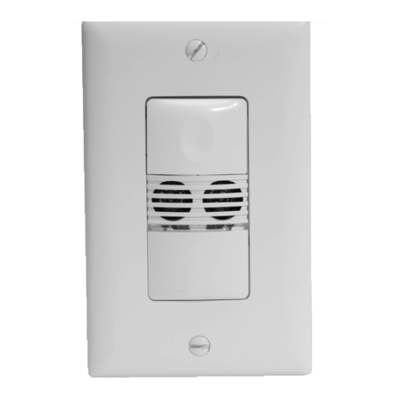
UW-100/UW-100-347
Ultrasonic Wall Switch
Occupancy Sensor
UW-200
/
UW-200
US Patents: 5640113
6617560
Santa Clara, CA 95050
800.879.8585
v3
Advertisement
Table of Contents

Related Manuals for LEGRAND WattStopper UW-100


Summary of Contents for LEGRAND WattStopper UW-100
- Page 1 UW-100/UW-100-347 UW-200 Ultrasonic Wall Switch Occupancy Sensor UW-100 & UW-100-347 UW-200 Specifications Voltages: UW-100 & UW-200 ....120/277VAC, 50/60Hz UW-100-347......347VAC, 50/60Hz Load Limits for each relay: @120VAC.
-
Page 2: Unit Description And Operation
UNIT DESCRIPTION AND OPERATION The UW Ultrasonic Wall Switch sensors employ 40kHz ultrasonic technology in a single-gang wall switch unit. The UW sensor can turn a load ON, and hold it ON as long as the sensor detects occupancy. After no movement is detected for the selected time delay, the lights switch OFF. -
Page 3: Time Delays
Presentation Mode is a feature of the Auto ON mode.When both relays are manually turned OFF the UW holds the lights OFF until no motion has been detected for the duration of the Time Delay. With subsequent occupancy, the UW turns the load ON. -
Page 4: Audible Alerts
Visible Alert The UW sensor can provide a visual alert as a warning one minute before the load turns OFF. Visible (DIP #5 ON) When only one minute is left in the time delay, the load connected to the relay turns OFF for one second. This provides a one minute warning before the load(s) are turned OFF by the sensor. -
Page 5: Installation
INSTALLATION WARNING TURN THE POWER OFF AT THE CIRCUIT BREAKER BEFORE INSTALLING THE SENSOR OR WORKING ON THE LOAD. 1. Make sure that the power has been turned OFF at the circuit breaker. 2. Connect wires to the UW flying leads as shown in the wiring diagram below that is appropriate to the UW model and electrical supply. -
Page 6: Dip Switch Settings
DIP SWITCH SETTINGS Relay 2 Mode Time 1 2 3 Time Delay Audible Not Used Delay Alerts Test/20 min 5 minutes Relay 1 Mode 10 minutes Manual On 15 minutes Auto On Walk-Through Relay 1 Mode 20 minutes Visible Alert 25 minutes UW-200 ONLY 30 minutes... -
Page 7: Sensor Adjustment
ADJUSTMENTS Sensor Adjustment Remove the wall plate. Remove the button cap by firmly squeezing together the top sides of the button assembly. Gently pull it away from the unit. When the adjustments are completed, replace the button cap by inserting its hinges into the tabs on the main unit and then squeeze the top of the button while pressing it into the unit. - Page 8 3. If lights still do not turn ON, call 800.879.8585 for technical support. Lights do not turn OFF 1. There can be up to a 30 minute time delay after the last motion is detected. To verify proper operation, set DIP switch 1 to ON, then reset switches 1, 2 and 3 to OFF to start Test Mode.
Need help?
Do you have a question about the WattStopper UW-100 and is the answer not in the manual?
Questions and answers