LEGRAND WattStopper UW-100 Installation Instructions Manual
Ultrasonic wall switch occupancy sensor
Hide thumbs
Also See for WattStopper UW-100:
- Installation instructions (4 pages) ,
- Installation instructions manual (9 pages) ,
- Installation instructions (4 pages)
Table of Contents
Advertisement
Quick Links
U W - 1 0 0 / U W - 1 0 0 - 3 4 7 / U W - 2 0 0
U W-100 & UW- 1 0 0 - 3 4 7
Specifications
Vo l ta ges:
UW-100 & UW-200 . . . . . . . . . . . . .1 2 0 / 2 3 0 / 2 7 7 VAC, 50/60Hz
U W - 1 0 0 - 3 4 7 . . . . . . . . . . . . . . . . . . . . . . . . . .3 4 7 VAC, 50/60Hz
Load Limits for each re l a y :
@ 1 2 0 VAC . . . . . . . . . . . .0-800W tungsten or ballast, 1/6 HP
@230 or 277VAC . . . . . . . . . . . . . . . . . . . . . . .0-1200W ballast
@ 3 4 7 VAC . . . . . . . . . . . . . . . . . . . . . . . . . . . . .0-1500W ballast
Load Type Compatibility:
I n ca n d e s cent, fluore s cent, magnetic or ele c t ronic ballast
H o rs e p ower Rating (each re l a y ) . . . . . . . . .1/6 HP @120VAC
Time Delay Adjust m e n t . . . . . . . . . . . . . . . . . . . .5 to 30 minute s
Wa l k - T h rough Mode . .3 minutes if no activity after 30 sec.
Te st Mode . . . 5 sec. at initial power up or DIP switch re s e t
U l t rasonic Adjust m e n t . . .Minimum to Maximum (trimpot), Off
Fre q u e n c y . . . . . . . . . . . . . . . . . . . . . . . . . . . . . . . . . . . .4 0 k H z
Light Level Adjust m e n t . . . . . . . . . . . . . . . . . . . . . . .8 fc to 180+fc
A le r t s
. . . . . . . . . . . . . . . . . . . . . .S e le c ta b le Audible & Visible
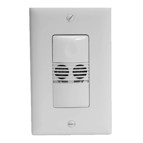
U l t rasonic Wall Switc h
O ccupancy Sensor
U W- 2 0 0
US Pa tents: 5640113
S a n ta Clara, CA 95050
8 0 0 . 8 7 9 . 8 5 8 5
6 6 1 7 5 6 0 B 2
Advertisement
Table of Contents

Subscribe to Our Youtube Channel
Related Manuals for LEGRAND WattStopper UW-100


Summary of Contents for LEGRAND WattStopper UW-100
- Page 1 U W - 1 0 0 / U W - 1 0 0 - 3 4 7 / U W - 2 0 0 U l t rasonic Wall Switc h O ccupancy Sensor U W-100 & UW- 1 0 0 - 3 4 7 U W- 2 0 0 Specifications Vo l ta ges:...
-
Page 2: Unit Description And Operation
UNIT DESCRIPTION AND OPERATION The UW Ultrasonic Wall Switch sensors employ 40kHz ultrasonic te c h n o logy in a single-gang wall switch unit. The UW sensor can turn a load ON, and hold it ON as long as the sensor detects occ u p a n c y. After no movement is dete c ted fo r the sele c ted time delay, the lights switch OFF. -
Page 3: Walk-Through
SmartSet™ auto The sensor re co rds typical occupancy patterns. Using this history (which is co n sta n t ly updated), it chooses an adjust time delay optimal time delay from 7 minutes (if the space is and Test Mode u s u a l ly va cant) up to 30 minutes (if the space gets heavy usage). -
Page 4: Coverage Patterns
COVERAGE PATTERNS C ove rage te sting has been performed acco rding to the NEMA WD 7 guideline. For best perfo r m a n ce, use in spaces not larger than 15’ x 15’. Ultrasonic Sensor The sensor has two ultrasonic tra n s ce i ve rs operating at 40kHz. Dete c t i o n sensitivity can be adjusted using the trimpot under the ON/OFF butto n s . -
Page 5: Installation
INSTALLATION WARNING TURN THE POWER OFF AT THE CIRCUIT BREAKER BEFORE INSTALLING THE SENSOR OR WORKING ON THE LOAD. 1 . M a ke sure that the power has been turned OFF at the circuit bre a ke r. 2 . Connect wires to the UW flying leads as shown in the wiring diagram below that is appro p r i a te to the UW model and ele c t r i cal supply. -
Page 6: Dip Switch Settings
DIP SWITCH SETTINGS ON/OFF Buttons Relay 1 Relay 2 Ultrasonic Sensitivity Adjustment Trimpot DIP Switches Tabs Ultrasonic Cones Green Ultrasonic Button Detection LED Hinges U W-200 shown. U W-100 has a single button and the Ultrasonic s e n s i t i v i t y adjustment trimpot is in a slightly different position. -
Page 7: Sensor Adjustment
ADJUSTMENTS Sensor Adjustment R e m ove the wall plate. Remove the button cap by firmly squeezing together the top sides of the button ass e m b ly. Gently pull it away from the unit. When the adjustments are co m p le ted, re p l a ce the button cap by inserting its hinges into the tabs on the main unit and then squeeze the top of the button while p re ssing it into the unit. -
Page 8: Ordering Information
Lights do not turn OFF 1 . T h e re can be up to a 30 minute time delay after the last motion is d e te c ted. To verify proper operation, set DIP switch 1 to ON, then re s e t s w i tches 1, 2 and 3 to OFF to start Te st Mode.
Need help?
Do you have a question about the WattStopper UW-100 and is the answer not in the manual?
Questions and answers