Table of Contents
Advertisement
Quick Links
Advertisement
Table of Contents

Subscribe to Our Youtube Channel
Related Manuals for Telit Wireless Solutions Bravo EVK


Summary of Contents for Telit Wireless Solutions Bravo EVK
- Page 1 Bravo EVK HW User Guide 1VV0301646 Rev. 1 – 2020-03-23 Mod. 0805 2017-01 Rev.6...
-
Page 2: Notice
Bravo HW User Guide SPECIFICATIONS ARE SUBJECT TO CHANGE WITHOUT NOTICE NOTICE While reasonable efforts have been made to assure the accuracy of this document, Telit assumes no liability resulting from any inaccuracies or omissions in this document, or from use of the information obtained herein. -
Page 3: Usage And Disclosure Restrictions
Bravo HW User Guide USAGE AND DISCLOSURE RESTRICTIONS License Agreements The software described in this document is the property of Telit and its licensors. It is furnished by express license agreement only and may be used only in accordance with the terms of such an agreement. -
Page 4: Applicability Table
Bravo HW User Guide APPLICABILITY TABLE PRODUCTS BRAVO EVALUATION KIT 1VV0301646 Rev. 1 Page 4 of 47 2020-03-23... -
Page 5: Table Of Contents
Bravo HW User Guide Contents NOTICE COPYRIGHTS ....................2 COMPUTER SOFTWARE COPYRIGHTS ............2 USAGE AND DISCLOSURE RESTRICTIONS ..........3 License Agreements ..............3 Copyrighted Materials ..............3 III. High Risk Materials ............... 3 Trademarks .................. 3 Third Party Rights ................. 3 APPLICABILITY TABLE ................ - Page 6 Bravo HW User Guide External Power Supply ..............33 Battery Charger ................34 3V3 Power Supply ..............36 ME910 Power Supply ..............37 RTC Battery ................38 1V8 Power Supply ..............39 Wake Switch ................40 Shutdown Switch ................ 40 Watchdog ...................
-
Page 7: Introduction
Bravo HW User Guide INTRODUCTION Scope Scope of this document is to describe the hardware components of the Bravo EVK board based on Telit ME910C1 module. Audience This document is intended for Telit customers, who are integrators, about to implement their applications using our Bravo EVK board. -
Page 8: Text Conventions
Bravo HW User Guide Text Conventions Danger – This information MUST be followed or catastrophic equipment failure or bodily injury may occur. Caution or Warning – Alerts the user to important points about integrating the module, if these points are not followed, the module and end user equipment may fail or malfunction. -
Page 9: Related Documents
Bravo HW User Guide Related Documents • ME910C1 HW User Guide, 1VV0301351 • xE910 Global Form Factor Application Note, 80000NT10060A 1VV0301646 Rev. 1 Page 9 of 47 2020-03-23... -
Page 10: Overview
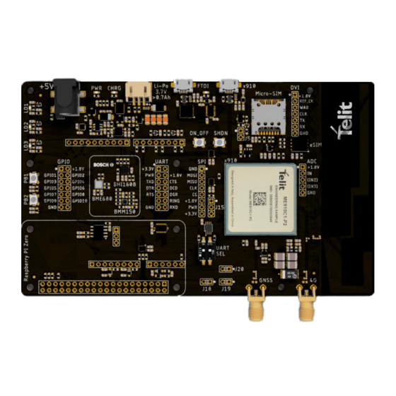
Bravo HW User Guide OVERVIEW The aim of this document is to describe the “Bravo” EVK board based on Telit ME910C1- WW IoT module. The Bravo board can be used in different configurations: • Standalone, using ME910C1 programmed with AppZone IDE •... - Page 11 Bravo HW User Guide Arduino and Raspberry PI boards cannot be connected at the same time Figure 1 - Bravo EVK Board Figure 2 - Bravo EVK Board - Top View 1VV0301646 Rev. 1 Page 11 of 47 2020-03-23...
- Page 12 Bravo HW User Guide Figure 3 - Bravo EVK Board with Arduino format board Figure 4 - Bravo EVK Board with Raspberry PI format board 1VV0301646 Rev. 1 Page 12 of 47 2020-03-23...
- Page 13 Bravo HW User Guide Figure 5 - Bravo EVK Board with Raspberry PI Zero format board 1VV0301646 Rev. 1 Page 13 of 47 2020-03-23...
-
Page 14: Notice
Bravo HW User Guide NOTICE While reasonable efforts have been made to assure the accuracy of this document, Telit assumes no liability resulting from any inaccuracies or omissions in this document, or from use of the information obtained herein. The information presented in this document is believed to be accurate and reliable. -
Page 15: Connectors
Bravo HW User Guide CONNECTORS Arduino Pin-out Figure 6 - Arduino Pinout Signal Function Type Comment POWER SUPPLY J10,2 IOREF I/O Level J10,5 External Power J10,6 J10,7 J10,8 Power from BRAVO board J12,7 GPIO INTERFACE J10,7 ARD_VUSB_910_ON USB Power on switch J13,8 ARD_910_SHDN ME910 SHDN Pin... - Page 16 An Arduino format board can be stacked on top of the Bravo board, connected to the J10, J11, J12 and J13 connectors. The Arduino board can be powered by the Bravo EVK board using the +5V from USBor J24 Power plug.
-
Page 17: Raspberry Pi Pin-Out
Bravo HW User Guide Raspberry PI Pin-Out Figure 7 - Raspberry PI Pinout Signal Function Type Comment POWER SUPPLY M2,1 +3V3_RPI Power M2,17 +3V3_RPI Power M2,2 +5V_RPI Power M2,4 +5V_RPI Power M2,6 Power M2,11 Power M2,14 Power M2,20 Power M2,25 Power M2,30 Power... - Page 18 RPI_RXD Serial data output to DTE The Raspberry PI board can power the Bravo EVK board, but not viceversa. All GPIOs are set to +3.3 V level: the +3V3_RPI signal goes to the VCCB on level translator and sets the interface B voltage level.
-
Page 19: Native Usb Connector
Bravo HW User Guide Native USB Connector Figure 8 - Native USB Signal Function Type Comment POWER SUPPLY J3,1 J3,5 USB HS 2.0 COMMUNICATION PORT (FW upgrade and Data) J3,2 USB_D- USB differential Data (-) J3,3 USB_D+ I/O USB differential Data (+) J3,4 USB OTG ID RESERVED The J3 USB plug is connected to the ME910 native USB port. - Page 20 Bravo HW User Guide Detaching VUSB from modem is mandatory to set the ME910 module into power saving mode. VUSB_910_ON is connected to an output pin of Arduino/RaspberryPI. For more details, “Arduino Pin-out” or “Raspberry PI please refer to the Pin-Out”...
-
Page 21: Spi Connector
Bravo HW User Guide SPI Connector Figure 9 - SPI Circuit The ME910 SPI interface pins are available on J16 connector, the U10 level translator port A is powered at the same voltage as the MCU IOs. The SPI Level translator B port is powered by +3V3 or VAUX_1V8 by shortening the 8,7 or 7,6 pin of J16 Outputs Switch to 3-State if either VCC is at GND or OE is high. - Page 22 Bravo HW User Guide J16,6 VAUX_1V8 J16,1 GPIO J16,5 SPI_MOSI Master Output Slave Input J16,4 SPI_MISO Master Input Slave Output J16,3 SPI_CLK Clock J16,2 SPI_CS Chip Select 1VV0301646 Rev. 1 Page 22 of 47 2020-03-23...
-
Page 23: Gpio Connectors
Bravo HW User Guide GPIO Connectors Figure 10 - GPIO Connectors Unused GPIO ports available externally thorough J21 and J22 connectors as listed in the table below Signal Function Type Comment POWER SUPPLY J21,1 VAUX_1V8 J22,1 VAUX_1V8 J21,5 J22,7 GPIO J21,2 ADC_IN ADC Input... - Page 24 Bravo HW User Guide Figure 11 - GPIO Connectors General Purpose IO pins are available at connector J14 and are shared with Sensors I2C, Buttons and Leds. For more details, please refer to “Sensors” and “Buttons and LEDs” chapters. Signal Function Type Comment...
-
Page 25: Sim Connectors
Bravo HW User Guide SIM Connectors Figure 12 - SIM Sockets The board can be fitted either with an eSIM in MFF2 format or a micro SIM socket: both inputs are ESD protected. 1VV0301646 Rev. 1 Page 25 of 47 2020-03-23... -
Page 26: Circuit Blocks
Bravo HW User Guide CIRCUIT BLOCKS Antennas Figure 13 – Antennas The ANTENNA Signal can be connected either to the PCB antenna or the SMA connector J4, which is disabled by default. In order to enable J4 and connect an external cellular antenna, remove R14 resistor and solder a 0-ohm resistor on R15 pads: this will disable the onboard cellular antenna. -
Page 27: Uart & Ftdi Usb
Bravo HW User Guide UART & FTDI USB Figure 14 - UART & FTDI USB The ME910 main UART is available for use with: • FTDI Serial to USB converter on port J9 • Arduino UART • Raspberry PI UART •... - Page 28 Bravo HW User Guide FTDI POWER SUPPLY J9,1 FTDI Power J9,5 FTDI COMMUNICATION PORT J9,2 USB_D- USB differential Data (-) J9,3 USB_D+ I/O USB differential Data (+) J9,4 USB OTG ID Signal Function Type Comment UART POWER SUPPLY J8,1 UART_PWR Power to Level Transaltor J8,2 VAUX_1V8...
- Page 29 Bravo HW User Guide Shorted Pins Function Comment UART Level Translator Voltage Selection J8 VAUX_1V8 to UART_PWR +3V3 to UART_PWR The +5V from the FTDI USB connector J9 can power the Bravo board. The FTDI serial to USB converter is powered only by the +5V signal from the J9 connector. The level translator connecting the Arduino UART to the ME910 UART is powered by IOREF signal from Arduino board: when the Arduino is not connected the level translator is in 3-state.
-
Page 30: Sensors
Bravo HW User Guide Control DTE to Computer (DTE) tells the DCE that it is ready to communicate. Raised by DTE when powered on. In auto- answer mode raised only when RI arrives from DCE Control DCE to Modem (DCE) tells the computer that it is ready to talk. Raised by DCE to indicate ready. - Page 31 Bravo HW User Guide GPIO Signal Type Direction Function I2C Signals Clock I2C clock signal from ME910 Data I2C Data Control Interrupt from BHI160B 1VV0301646 Rev. 1 Page 31 of 47 2020-03-23...
-
Page 32: Buttons And Leds
Bravo HW User Guide Buttons and LEDs Figure 17 - Pushbuttons and Leds The Bravo board has two user-available pushbuttons: PB3 and PB4 and three LEDs, LD1, LD2 and LD3. The leds are ON when the MCU pin is high. These signals are available at GPIO connector J14: please refer to chapter “GPIO Connectors”... -
Page 33: External Power Supply
Bravo HW User Guide External Power Supply Figure 18 - Power Supply The + 5V voltage level that powers the 3.8 V power supply can be supplied by different external sources: • USB ports (FTDI or ME910 native USB port) •... -
Page 34: Battery Charger
Bravo HW User Guide Battery Charger Figure 20 - Battery Charger A +3.7 V Lipo battery (not included) connected to J17 can power the Bravo board and can be charged by the onboard charger: the circuit receives +5V from the external power supply. - Page 35 Bravo HW User Guide Battery connector J17 is S3B-PH-SM4-TB. Figure 21 - Battery Connector Function Comment Battery Temperature sensor WARNING Use Li-Ion battery V = 3.7V, V = 4.2V Capacity >= 700 mAh chrg Li-Po batteries are charged at 4.2V with a current that is usually half the nominal capacity (C/2).
-
Page 36: 3V3 Power Supply
Bravo HW User Guide 3V3 Power Supply Figure 22 - 3V3 Power Supply The Bravo board also provides a +3.3 V power source to power LEDs and Level Translator for UART connection. 1VV0301646 Rev. 1 Page 36 of 47 2020-03-23... -
Page 37: Me910 Power Supply
Bravo HW User Guide ME910 Power Supply Figure 23 - ME910 Power Supply Circuit Power is delivered from VCC_910 to the ME910 module using the above pictured circuit. R66, R67 and R68 resistors can be removed and connectors J18, J19 and J20 can be used to measure current consumption. -
Page 38: Rtc Battery
Bravo HW User Guide RTC Battery Figure 24 - RTC battery power supply The VRTC pin available on some ME910 variants can be connected to a coin battery by means of a LDO power supply. This circuit is actually not mounted on the Bravo board, but is described here for future use. -
Page 39: 1V8 Power Supply
Bravo HW User Guide 1V8 Power Supply Figure 25 - ME910C1 internal power supply The ME910C1 module is powered at 3.8 V, but all I/O operate at 1.8 V: the VAUX/PWRMON provides the 1.8 V level to be used by level translators and onboard Bosch sensors. -
Page 40: Wake Switch
Bravo HW User Guide Wake Switch Figure 26 - ON/OFF Switch Circuit The ON_OFF#/WAKE# pin can be controlled by the PB3 bush-button or by the 910_ON_OFF signal that is connected to ARD_910_ON_OFF or RPI_910_ON_OFF signal coming from Arduino or Raspberry PI connected boards respectively. For additional details, please refer to chapter “Arduino Pin-outArduino Pin-out”or “Raspberry PI Pin-Out”. -
Page 41: Watchdog
Bravo HW User Guide Watchdog Figure 288 - Watchdog Circuit The HW_SHUTDOWN# and ON_OFF#/WAKE# pins can be controlled the U11A STM8L microcontroller to enable whatchdog functionality. The WDT chip is not mounted by default. 1VV0301646 Rev. 1 Page 41 of 47 2020-03-23... -
Page 42: Mechanical Design
Bravo HW User Guide MECHANICAL DESIGN Drawing 1VV0301646 Rev. 1 Page 42 of 47 2020-03-23... -
Page 43: Safety Recommendations
Bravo HW User Guide SAFETY RECOMMENDATIONS READ CAREFULLY Be sure the use of this product is allowed in the country and in the environment required. The use of this product may be dangerous and has to be avoided in the following areas: •... -
Page 44: Acronyms
Bravo HW User Guide ACRONYMS Telit Technical Support Centre TTSC Universal Serial Bus High Speed Data Terminal Equipment Universal Mobile Telecommunication System UMTS Wideband Code Division Multiple Access WCDMA High Speed Downlink Packet Access HSDPA High Speed Uplink Packet Access HSUPA Universal Asynchronous Receiver Transmitter UART... - Page 45 Bravo HW User Guide Slave Ready SRDY Chip Select Real Time Clock Printed Circuit Board Equivalent Series Resistance Voltage Standing Wave Radio VSWR Vector Network Analyzer 1VV0301646 Rev. 1 Page 45 of 47 2020-03-23...
-
Page 46: Document History
Bravo HW User Guide DOCUMENT HISTORY Revision Date Changes 2020-02-21 Initial revision 2020-03-23 DIP Switch table added 1VV0301646 Rev. 1 Page 46 of 47 2020-03-23... - Page 47 Mod. 0805 2017-01 Rev.6...
Need help?
Do you have a question about the Bravo EVK and is the answer not in the manual?
Questions and answers