Telit Wireless Solutions xE910 User Manual
Hide thumbs
Also See for xE910:
- User manual (47 pages) ,
- User manual (56 pages) ,
- Hardware reference manual (10 pages)

Related Manuals for Telit Wireless Solutions xE910


Summary of Contents for Telit Wireless Solutions xE910
- Page 2 APPLICABILITY LIST: Model Part Number Product xE910 Development Board (Socket) 3990150528 Multi (Socket adapter) Reproduction forbidden without Telit Communications S.p.A. written authorization - All Rights Reserved page 2 of 49...
- Page 3 SPECIFICATIONS SUBJECT TO CHANGE WITHOUT NOTICE Notice While reasonable efforts have been made to assure the accuracy of this document, Telit assumes no liability resulting from any inaccuracies or omissions in this document, or from use of the information obtained herein. The information in this document has been carefully checked and is believed to be entirely reliable.
- Page 4 supplied SW, except for the normal non-exclusive, royalty free license to use that arises by operation of law in the sale of a product. Usage and Disclosure Restrictions License Agreements The software described in this document is the property of Telit and its licensors. It is furnished by express license agreement only and may be used only in accordance with the terms of such an agreement.
- Page 5 Contents Introduction ..........................7 1.1. Scope ..............................7 1.2. Audience ..............................7 1.3. Contact Information, Support ......................7 1.4. Text Conventions ..........................8 1.5. Related Documents ..........................8 1.6. Content of the kit ..........................9 Description ..........................10 Startup procedure ........................11 Power Supply Section ......................
- Page 6 7.6. Audio Settings ............................. 32 7.6.1. Hi Power Amplifier Gain ........................33 7.6.2. DVI Connections ............................ 33 7.6.3. Analog Audio Inputs and Outputs ......................34 7.6.4. Digital Audio Inputs and Outputs ......................34 7.6.5. Digital MIC Inputs ..........................34 7.6.6. PL701 Setting Examples .........................
- Page 7 Purpose of this manual is to describe the use of the Telit xE910 Development Board. All given information shall be used as a guide and a starting point for properly developing of your product. Obviously this document cannot cover all the hardware solutions and products that may be designed.
- Page 8 Danger – This information MUST be followed or catastrophic equipment failure or bodily injury may occur. All dates are in ISO 8601 format, i.e. YYYY-MM-DD. Telit’s GSM/GPRS Family Software User Guide, 1vv0300784 Audio settings application note , 80000NT10007a Digital Voice Interface Application Note, 80000NT10004a HE910 Digital Voice Application Note, 80000NT10050a SIM Holder Design Guides, 80000NT10001a AT Commands Reference Guide, 80000ST10025a...
- Page 9 Please check out the content of your xE910 Development Board kit; if any of the items is missing, please contact your supplier. Description Quantity xE910 Development Board INFORMATION NOTE ASSEMBLED USB A-Mini USB CABLE 12V DC Power Supply RED & BLACK CABLE WITH PLUGS...
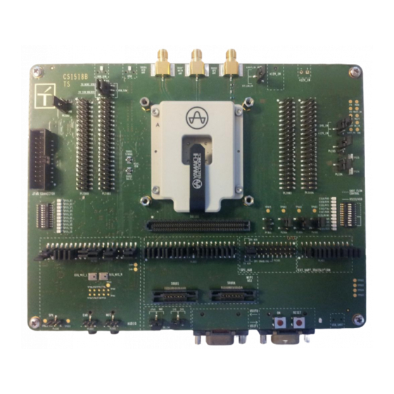
- Page 10 The xE910 Development Board can be split into several functional blocks depending on the implemented function; the following drawing shows the main blocks on the board: Reproduction forbidden without Telit Communications S.p.A. written authorization - All Rights Reserved page 10 of 49...
- Page 11 The motherboard factory setup is: Serial port USIF 0 and USIF 1 on USB UART DC source 12V only Audio Available on MIC/EAR DVI connected Follow this sequence of commands to use the Development Board: insert your SIM card set properly all jumpers in the desired position connect the antenna to RF connector connect the audio accessories if required Insert the module in the Socket (ensure to properly place the module in it following the...
- Page 12 The following picture is showing the board section related to the Power supply: The Development Board could be powered in two different ways: 12V DC using the provided Power supply 3.8V DC using the provided red/black cable The requested setting is made inserting the proper jumper connectors in the right position as described in the next paragraphs.
- Page 13 There are 3 Jumpers on this section that could be used to configure it: PL102 This Jumper could be used to select if the board is supplied by using the 12V to 3.8V switching from SO101 or by the direct supply to VBATT (3.8V to TP103/TP104). 1) Power supply using the Switching 12V to 3.8V Jumper between pin 2 and 3 (default setting) 2) Power supply using the 3.8V input for VBATT...
- Page 14 This is the main power supply of the Development Board and it is the suggested method to be used with this device. You could use the provided 12V power supply plugging its connector to SO101. As described above to use this Power supply input the PL201 Jumper has to be set between pin 2 and 3.
- Page 15 If you want to use your own 12V DC power supply, the minimum characteristics to be supported are the following: Characteristic Value Unit Nominal dc output voltage Rating load current minimum 1.25 Ripple 120 p-p Rise time less than 20 Output connector dc plug type: 5.5*2.5*11 Center “+”...
- Page 16 The following schematic is related to the 12V to 3.8V switching regulator Reproduction forbidden without Telit Communications S.p.A. written authorization - All Rights Reserved page 16 of 49...
- Page 17 It is possible to control the module’s ON_OFF and RESET lines using two buttons present on the Development Board. This button permits to power on and off the module. Its behaviour and the related reaction time has to be checked on the product’s Hardware User Guide.
- Page 18 The xE910 Development board is permitting to interface the module using all the supported communication ports. The UART section of the Development Board is shown in the following picture: This section is related to interface the USIF0 (Main serial port of the module) and the USIF1 (Auxiliary serial port of the module).
- Page 19 Communications between your application and the Telit modules are allowed connecting the DTE to the Asynchronous Serial Interfaces of Base-Band Chip, USIF0 and USIF1, through the two standard RS232 communications ports (9 way D-socket connector at slow data rates of RS232 protocol) or a standard Mini USB receptacle. The selection between D-Socket and USB is done using the SW901 switch.
- Page 20 The Development Board is provided by a section that permit to force/show the status of the Serial Port Lines. The following Image shows where the controls are located. There is a set of LED that is showing the status of the Serial Port lines and a Switch (SW901) that permits to force the Flow control Lines to a defined state: The ON Position of the switches means signal set to LOW state.
- Page 21 The USB port section of the Development Board is shown in the following picture: The USB HS port is related to the connector named as USB MAIN. The connector is a MINI USB. When the USB is connected the led DL202 will be lighted on. Reproduction forbidden without Telit Communications S.p.A.
- Page 22 The Development board is provided by a SIM Holder and a M2M SIM that could be selected using the Jumper PL1201. The Development Board is provided by a push-push SIM Holder and the following image is showing its position and how to insert the SIM. The Jumper on PL1201 permits to select the used SIM.
- Page 23 The Development Board is provided by a M2M SIM that could be enabled using the PL1201; M2M SIM Jumper removed The command AT#SIMDET=1 should be provided in this case. Reproduction forbidden without Telit Communications S.p.A. written authorization - All Rights Reserved page 23 of 49...
- Page 24 This section of the Development Board permits to interface the DVI of the module and, when supported, the Analog Audio. The Board is equipped with the following functionalities: 1 Audio Codec usable in connection with the module’s DVI 1 Audio amplifier section that could interface the Analog Audio 1 additional HI Power Audio amplifier (15W) The Audio section on the Development board is shown in the following image: Reproduction forbidden without Telit Communications S.p.A.
- Page 25 PL701 permits to set the different configurations of the Audio section. PL601 or SO601 are permitting to connect an external Microphone PL602 or SO602 are permitting to connect an external Earpiece PL606 is the output of the High Power Amplifier Reproduction forbidden without Telit Communications S.p.A.
- Page 26 The board is provided by an Audio codec (MAX9867ETJ from Maxim) that could be used to interface the Module’s DVI. The schematic is the following: The CODEC is programmed through the I2C using two GPIOs of the module (GPIO_08 for I2C_SCL and GPIO_09 for I2C_SDA) In this schematic the configuration is for a Stereo Input and Output.
- Page 27 The Development Board is provided by a set of possible Audio inputs to interface the Audio circuitry (i.e. Audio Codec) or directly the module. Its configuration could be set using the Jumpers on PL701. You could refer to the “Audio Settings” paragraph for the details. The schematic of this section is the following: Reproduction forbidden without Telit Communications S.p.A.
- Page 28 This circuit permits to connect a standard electret microphone. It could be connected using the SO601 connector (Jack 3.5mm) where the jack contacts are described in the following Image: Or using the PL601 connector where the pin-out is the following: 1) BIAS/R_MIC Signal 2) GND 3) L_MIC Signal...
- Page 29 The Development Board is provided by a set of possible Audio Outputs to interface the Audio circuitry (i.e. Audio Codec) or directly the module. Its configuration could be set using the Jumpers on PL701. You could refer to the “Audio Settings” paragraph for the details. This part of the circuit permits to amplify the audio signal coming from the Codec or directly from the Analog Audio output from the module.
- Page 30 This circuit permits to connect a headset using the SO602 connector (Jack 3.5mm) where the jack contacts are described in the following Image: Or using the PL602 connector where the pin-out is the following: 1) RIGHT_EAR 2) GND 3) LEFT_EAR Reproduction forbidden without Telit Communications S.p.A.
- Page 31 The Development Board is provided by an additional High Power Audio Amplifier. It is developed using the MAX98400A from Maxim and it is a Class D amplifier capable to deliver 40W into 4 ohm load. The Schematic is in the following Image: The external 4 ohm Speaker could be connected to PL606 between pin 1 and 2.
- Page 32 LOUTN_CODEC LOUTN line (CODEC) LOUTP LOUTP line (MAX9722A) LOUTN LOUTN line (MAX9722A) EAR+_F EAR+ Analog line (filtered from xE910) EAR-_F EAR- Analog line (filtered from xE910) EAR+_F EAR+ Analog line (filtered from xE910) EAR-_F EAR- Analog line (filtered from xE910)
- Page 33 The Audio circuitry could be set to interface or the DVI or the Analog Audio of the module. It is not possible to use in the same moment the Codec and the Analog Audio Lines. The following Image is showing the factory default settings: The pins 1 to 8 permit to set the Max98400 Amplifier gain.
- Page 34 The Pins from17 to 28 permits to select the Input Audio lines. The pins from 28 to 40 are related to the Output Audio lines. The settings to select the Analog Audio lines are the following: Signal Setting Audio Input (SO601, PL601) connected Jumper on 17-19 and 18-20 to module’s MIC signals.
- Page 35 This setting permit to have the Audio Codec connected to the DVI port of the module The programming of the codec is done using two GPIO’s (GPIO8 and GPIO9) controlled by SW as an I2C port. This setting permit to use the Analog Audio signals (for Module’s supporting this feature). Reproduction forbidden without Telit Communications S.p.A.
- Page 36 The following tables show the suggested specification to obtain the best performance from off-the-shelf accessories. This section describes the typical characteristics of the Microphone and Earpiece to be used with the Development Board. MICROPHONE Nominal sensitivity -45dBV /1Pa (+/- 3dB) Line coupling Nominal Voltage Range of Using Voltage...
- Page 37 The Development board is provided by 3 Antenna connectors (SMA Female) and , depending to the supported features of the assembled module, permits to connect an Antenna to the module. The connectors are on the upper part of the Board and the following image is detailing the assigned function: The Development Board is provided by a circuitry capable to supply an Active GPS...
- Page 38 The STAT_LED shows information on the network service availability and Call status. The function is available as alternate function of GPIO_01 (to be enabled using the AT#GPIO=1,0,2 command). Please refer to the module’s HW User Guide to have the details on the STAT LED behavior. The following Image shows the LED Position: Reproduction forbidden without Telit Communications S.p.A.
- Page 39 The Development Board is providing an indication of the GPIO status (LED) and a possibility to force the GPIO status to LOW using a Switch (SW902): The layout of that PCB area is in the following image: The GPIO Status Switch and corresponding controlled line is in the below Image: The ON position on the Switch means signal set to GND.
- Page 40 The Development Board offers a set of connectors that hosts all the module’s signals in case the developer needs to interface directly the module with its application. The connectors are named PL1001, PL1002, PL1003, PL1004 and their position on the board is in the following image: The following Chapters will detail the connectors pin-out Reproduction forbidden without Telit Communications S.p.A.
- Page 41 Signal Name Function Type Comment Ground Power Ground Power Ground Power Ground Power ADC_IN1 Analog / Digital converter input Accepted values 0 to 1.2V DC Reserved Reserved Reserved Reserved Reserved Ground Power SIMVCC SIM Power Supply 1.8 / 3V SIMIN SIM Presence (active low) CMOS 1.8 SIMIO...
- Page 42 Signal Name Function Type Comment Ground Power Ground Power Reserved Reserved Reserved Reserved Reserved VRTC VRTC Backup capacitor Power RTC Backup (1.8V) 1V8_SEL 1V8 SEL for VDD_IO1 1V8_SEL VDD_IO1 VDD_IO1 Input VDD_IO1 Reserved Ground Power GPIO_07 GPIO_07 CMOS 1.8V Reserved C125/RING Output for Ring (RI) to DTE CMOS 1.8V...
- Page 43 Signal Name Function Type Comment Ground Power Ground Power Ground Power Ground Power Reserved Reserved Ground Power Ground Power Ground Power Ground Power VBATT Main power supply (Baseband) Power VBATT Main power supply (Baseband) Power VBATT_PA Main power supply (Radio PA) Power VBATT_PA Main power supply (Radio PA)
- Page 44 Signal Name Function Type Comment Ground Power Ground Power Ground Power Ground Power GNSS_NMEA_TX GNSS Serial Port (TX) CMOS 1.8V GNSS_NMEA_RX GNSS Serial Port (RX) CMOS 1.8V GNSS_EN GNSS Enable Reserved Reserved Reserved Reserved Reserved Reserved Reserved Reserved Reserved Reserved Reserved Reserved Reserved...
- Page 45 When the USB UART port is connected to the PC the system will detect 4 Serial Ports. Please select the xE910 Development Kit USB drivers when required. The ports will be recognized as “xE910 Dev Board USB <--> Serial” Then after the driver installation the system will list 4 new Serial Ports:...
- Page 46 READ CAREFULLY Be sure the use of this product is allowed in the country and in the environment required. The use of this product may be dangerous and has to be avoided in the following areas: Where it can interfere with other electronic devices in environments such as hospitals, airports, aircrafts, etc Where there is risk of explosion such as gasoline stations, oil refineries, etc It is responsibility of the user to enforce the country regulation and the specific environment...
- Page 47 According to the directives 2002/95/CE, 2002/96/CE and 2003/108/CE, which have been transposed in Italian Legislative Decree of July 25, 2005, n. 151, Telit Communications S.p.A informs that: The symbol of the crossed-out wheeled bin reproduced on the product or on the packaging, indicates that the product, at the end of life cycle, must be gathered separately from the other waste.
- Page 48 This symbol, applied on our products and/or on its packaging, indicates that this product should not be treated as household waste when you wish to dispose of it. Instead, it should be handed over to an applicable collection point for the recycling of electrical and electronic equipment. By ensuring this product is disposed of correctly, you will help prevent potential negative consequences to the environment and human health, which could otherwise be caused by inappropriate disposal of this product.
- Page 49 Revision Date Changes Rev 0 2013-10-22 First issue Reproduction forbidden without Telit Communications S.p.A. written authorization - All Rights Reserved page 49 of 49...
Need help?
Do you have a question about the xE910 and is the answer not in the manual?
Questions and answers