
Related Manuals for Telit Wireless Solutions EVB 2.0


Summary of Contents for Telit Wireless Solutions EVB 2.0
- Page 1 Telit EVB2.0 User Guide 1VV0301732 Rev. 1 – 2021-10-18 Telit Technical Documentation...
-
Page 2: Applicability Table
PRODUCTS All modules available on a legacy TLB All modules available on a smart TLB • First release of EVB 2.0 (based on CS2125). • EVB2.0 2 release (based on CS2148) will include some changes compared to the first release. -
Page 3: Table Of Contents
Telit EVB2.0 User Guide CONTENTS APPLICABILITY TABLE CONTENTS INTRODUCTION Scope Audience Contact Information, Support Symbol Conventions GENERAL PRODUCT DESCRIPTION Overview Block Diagram EVB2.0 Target TLB Types Main Features Main Electrical Specifications Mechanical Specifications 2.5.1. Dimensions 2.5.2. Temperature Range 120-PIN MALE B2B CONNECTORS B2B Connectors Layout (Top View) B2B Connectors Pinout POWER SUPPLY... - Page 4 Telit EVB2.0 User Guide 4-Wires Connection for DIRECT SUPPLY 4.5.1. Direct Supply Power Consumption Measurement 4.6.1. Measure the Current by a Current Meter 4.6.2. Measure the Current by a Power Supply 4.6.3. Measure the Current through the Shunt Resistor VAUX/PWRMON Power Output DIGITAL SECTION Power On Communication Ports...
- Page 5 Telit EVB2.0 User Guide Electrical Characteristics MECHANICAL SPECIFICATIONS Drawing PRODUCT AND SAFETY INFORMATION Copyrights and Other Notices 8.1.1. Copyrights 8.1.2. Computer Software Copyrights Usage and Disclosure Restrictions 8.2.1. License Agreements 8.2.2. Copyrighted Materials 8.2.3. High Risk Materials 8.2.4. Trademarks 8.2.5. Third Party Rights 8.2.6.
-
Page 6: Introduction
Telit EVB2.0 User Guide 1. INTRODUCTION Scope This document introduces the Telit EVB2.0 and presents possible hardware solutions for the development of a product based on the Telit modules. The features and solutions described in this document are applicable to the variants listed in the applicability table. This document may not include all hardware solutions or products that can be designed. -
Page 7: Symbol Conventions
Telit EVB2.0 User Guide Symbol Conventions Danger: This information MUST be followed, or catastrophic equipment failure or personal injury may occur. Warning: Alerts the user on important steps about the module integration. Note/Tip: Provides advice and suggestions that may be useful when integrating the module. -
Page 8: General Product Description
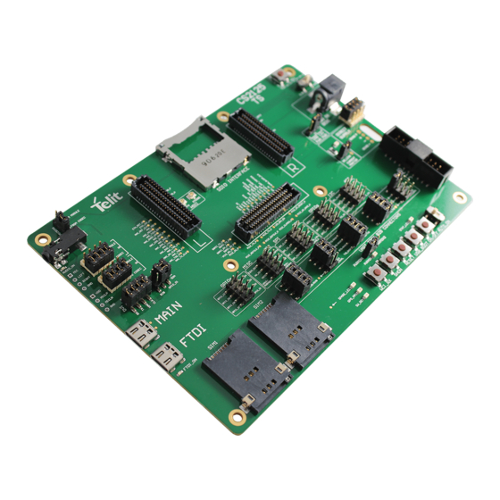
2. GENERAL PRODUCT DESCRIPTION Overview Telit EVB 2.0 system consists of a main board, as well as connectors, cables, accessories, and software. It is designed to host Telit modules allowing users to easily test the main module functions and features. -
Page 9: Evb2.0 Target
Telit EVB2.0 User Guide Of course, some circuit parts can be used as examples or inspirations, but in some cases, end product design solutions should be tailored to specific applications. The modem communicates with the host PC via two USB-C cables: one for the module USB communication port and the other for serial lines, through a USB to serial converter. -
Page 10: Main Features
Telit EVB2.0 User Guide TLB TAG Description The TLBs developed before this EVB, for modules with V =3.8V. batt LGCY38 TLB The voltage selector must be set at 3.8V. The TLBs developed before this EVB, for modules with V =3.3v. batt LGCY33 TLB The voltage selector must be set to 3.3V. -
Page 11: Main Electrical Specifications
Telit EVB2.0 User Guide Function Features When VIA DCDC mode is used, an external PC can control the regulator: it can be switched ON or OFF and the voltage can be set as desired 2 SIM holder • There are 2 SIM holders, for module supporting 2 SIM interfaces •... -
Page 12: Mechanical Specifications
Telit EVB2.0 User Guide Mechanical Specifications 2.5.1. Dimensions The overall dimensions of EVB2 (CS2125 PCB version) are: • Size: 156x110 [mm] • PCB Thickness: 1.6 [mm] 2.5.2. Temperature Range Mode Temperature Note SIM CARDs might not withstand extreme –20°C ÷ +55°C temperatures Operating Temperature Range The board (except SIM cards) is fully functional... -
Page 13: 0-Pin Male B2B Connectors
Telit EVB2.0 User Guide 3. 120-Pin male B2B Connectors B2B Connectors Layout (Top View) The connection between EVB and TLB is implemented via three 120-poles (20 poles x 6 rows) SAMTEC SEARAY 1.27mm High Speed/High Density B2B connectors (10mm stack height SEAM/SEAF). -
Page 14: B2B Connectors Pinout
Telit EVB2.0 User Guide B2B Connectors Pinout B2B L (LEFT) GPS_LNA_BIAS GPS_LNA_EN MICBIAS_MODULE NC / JACK_DET MIC2_MT+ MIC2_MT- EAR2_MT- EAR2_MT+ MIC1_MT+ MIC1_MT- EAR1_MT- EAR1_MT+ RESERVED SPKR_N SPKR_P MIC_VDD (DON'T USE) D_MIC_CLK D_MIC_DATA_1 ADC_IN3 ADC_IN2 ADC_IN1 DAC_OUT DVI_RX DVI_TX DVI_CLK DVI_WAO REF_CLK_FF ESIM_RST SIMVCC1... - Page 15 Telit EVB2.0 User Guide B2B C (CENTRAL) I2C_SCL_AUX I2C_SDA_AUX SGMII_RX_M USB_SS_RX_P I2C_SDA_B2B TGPIO_06 SGMII_TX_M SGMII_RX_P USB_SS_RX_M TGPIO_05 I2C_SCL_B2B SGMII_TX_P VAUX/PWRMON2 VAUX/PWRMON2 PCIE_RX_P FORDCED_USB_B USB_SS_TX_P PCIE_TX_P PCIE_RX_M NetSO101_45 TGPIO_12 SPI_MOSI PCIE_TX_M PCIE_REFCLK_ TGPIO_11 TGPIO_04 PCIE_REFCLK_ #SPI_CS TGPIO_02 TGPIO_03 SPI_MISO VAUX/PWRMON1 VAUX/PWRMON1 LED_DRV_EN SPI_CLK TGPIO_08...
- Page 16 Telit EVB2.0 User Guide B2B R (RIGHT) VBATT VBATT VBATT VBATT_PA VBATT_PA VBATT_PA VBATT VBATT VBATT VBATT_PA VBATT_PA VBATT_PA VBATT VBATT VBATT VBATT_PA VBATT_PA VBATT_PA VBATT_AUX VBATT_AUX VBATT_AUX VBATT_PA VBATT_PA VBATT_PA DCDC_ADJ LDO_ADJ DCDC_OUTPUT 3V8_EVB DCDC_ADJ_2 DCDC_OUTPUT_2 DCDC_OUTPUT_2 DCDC_OUTPUT_2 UART3_TXD UART3_RXD UART3_RTS UART3_CTS...
-
Page 17: Power Supply
Telit EVB2.0 User Guide 4. POWER SUPPLY During final product development phases, it might be necessary to supply the module with low-level voltages (either 1.8V, 3.3V, or 3.8V) from an external DC source located close to the board and through a wire of adequate section. This case is defined as “DIRECT SUPPLY”. -
Page 18: Example Use Cases
Telit EVB2.0 User Guide Example Use Cases Use Case 1: The TLB is powered externally by DIRECT SUPPLY, while the EVB is powered by VIA DCDC. The EVB must always receive 3.8 V, so it is most frequently connected to the internal fixed regulator. -
Page 19: Batt Voltage Level
Telit EVB2.0 User Guide Note: Please see section 4.6 Power Consumption Measurement for more information and use cases. Voltage Level batt Telit modules typically require either 3.8V, data cards require 3.3V, and 1.8V is the standard voltage for positioning modules. Please follow the guidelines below to provide the correct voltage to each Telit module: •... -
Page 20: Source Selector
Telit EVB2.0 User Guide Figure 6: No-leak Jumper 4.3.2. Source Selector When the VIA DCDC mode for some supply rail is used, it is possible to select the power source: it can be supplied either from the dedicated 5.5x2.5 mm jack or from the 5V USB- MAIN (USB-DEVICE). -
Page 21: Voltage Selector
Telit EVB2.0 User Guide 4.3.3. Voltage Selector On the legacy TLB board (developed before EVB2 introduction), no AVS (Automatic Voltage Selector) is available, thus the DCDC regulator must be set to the voltage needed by the device using the voltage selector switch. With the jumper set on the left position, the voltage is set to 3.3V. -
Page 22: 4-Wires Connection For Direct Supply
Telit EVB2.0 User Guide In VIA DCDC mode, the wall adapter connected to the jack can supply a voltage in the 5V- 12V range. The regulator can accept up to 36V (42V absolute maximum) but, in this case, the output voltage (V ) will not be properly regulated. -
Page 23: Power Consumption Measurement
Telit EVB2.0 User Guide Figure 10: Direct Supply Power Consumption Measurement The EVB not only allows different power supply configurations (as explained in the previous chapter), but at the same time supports different methods to measure current consumption of the Telit module connected to the EVB: 1. -
Page 24: Measure The Current By A Current Meter
Telit EVB2.0 User Guide 4.6.1. Measure the Current by a Current Meter The board is fully powered VIA DCDC. The current consumption of the device can be measured by placing an Ammeter in series to the desired rail. The image below shows the VBATT measurement configuration. Please ensure that the ammeter wires are properly sized. -
Page 25: Measure The Current By A Power Supply
Telit EVB2.0 User Guide 4.6.2. Measure the Current by a Power Supply In this case, only the device is powered by an external source via DIRECT SUPPLY, while the TLB's auxiliary parts and the EVB board are powered via DCDC. Obviously, a key requirement is that the external power supply must be able to perform current measurements. -
Page 26: Measure The Current Through The Shunt Resistor
Telit EVB2.0 User Guide 1. Remove the NO-LEAK JUMPER(PL301) 2. Cut the coffee-bean shaped bridge Figure 16: Avoiding Leakage Current 4.6.3. Measure the Current through the Shunt Resistor The device is exclusively powered VIA DCDC. The device current consumption is indirectly measured by measuring the voltage across the 50 mΩ... - Page 27 Telit EVB2.0 User Guide approach in EVB2 design is to avoid drawing current from this port and use 3V8_EVB as source. At the same time, if desidered, VAUX/PWRMON1/2 pins are available for supplying the translators through a 0-Ohm jumper. They are available as well on their pin header to allow the user to connect external application hardware and test the system.
-
Page 28: Digital Section
Telit EVB2.0 User Guide 5. DIGITAL SECTION Most of the device pins available on the to EVB are digital. Its supply domain is VDDIO_1V8/2V8 and is set to 1.8V or 2.8V depending on the device (legacy TLB’s are satisfied with 1.8V, smart TLB’s set the voltage by its own). These signals mostly terminate on a male connector, allowing the user to connect to other boards using wire jumpers. -
Page 29: Communication Ports
5.2.1. USB DEVICE (MAIN) and USB AUX (FTDI) The EVB mounts two USB-C connectors, labeled “MAIN” and “FTDI” on the initial EVB 2.0 board revision silk screen (based on CS2125 PCB revision), “DEVICE” and “AUX” on the second EVB 2.0 board revision. -
Page 30: Uarts Pins Naming Convention
Telit EVB2.0 User Guide Figure 19: USB DEVICE (MAIN) and USB AUX (FTDI) The 3 UART lines are connected to the device serial lines and are mapped as Virtual Com Ports on the host PC. Note: When the USB DEVICE is used as a power source, make sure the USB cable is as short and thick as possible, in order to avoid voltage drops on the cable that can cause issues. -
Page 31: Sim Card Holders
Telit EVB2.0 User Guide UART3 SERIAL is a spare serial port, often used by the GNSS receiver integrated • in cellular devices Each serial line must be configured as 115200 8-N-1, unless otherwise specified. Serial port lines can be monitored (eg with a scope or logic state analyzer) or disconnected, thanks to dedicated jumpers placed on the front of the board. -
Page 32: Leds
Telit EVB2.0 User Guide Figure 21: SDIO Interface LEDs 5.5.1. Peak Current When exceeding about 100mA current draw, the LED switches on. 5.5.2. STAT_LED Indication of Network Service Availability The STAT_LED pin status displays network service availability and call status. The function is available as an alternative function of GPIO_01 (to be enabled by means of the AT#GPIO=1,0,2 AT command). -
Page 33: Ftdi On
Telit EVB2.0 User Guide The indication is supported for both digital and analog audio chains. 5.5.4. FTDI ON This LED switches on when the host PC operating system enumerates the USB instance of the FTDI level converter. 5.5.5. PWRMON This LED switches on when the host PC operating system enumerates the module USB instance. -
Page 34: On/Off
Telit EVB2.0 User Guide 5.6.3. ON/OFF This is the ON/OFF push button: keeping it pressed for a few seconds switches the device ON or OFF. The adjacent “AUTO_ON” switch, is a “comfort gadget” for users who want to emulate ON/OFF button always pressed. When activated, it “holds down” the ON/OFF push button permanently. -
Page 35: Audio Section
Telit EVB2.0 User Guide 6. AUDIO SECTION The EVB2 AUDIO interface includes an headphone amplifier, typically not present on Telit evaluation boards: this solution was chosen since loudspeakers are referenced to ground, thus avoiding tantalum DC block capacitors causing audio clicks and pops. The user interface is a CTIA standard handfree TRRS 3.5mm jack or a 4 test points array in 2.54mm pitch. -
Page 36: Electrical Characteristics
Telit EVB2.0 User Guide To provide the user with maximum flexibility, all audio and codec signals are routed through a pair of jumpered headers. In example, a handsfree can be connected directly and jumpers can be removed to connect external circuitry. To initialize the audio codec using GPIO1 as SDA and GPIO2 as SCL, the following commands from the AT interface must be sent: •... - Page 37 Telit EVB2.0 User Guide Signal I/O for the device Function Type Output for Device (MASTER) CMOS DVI_WA0 Digital Audio Interface (Word Alignment / LRCLK) Input for Device (SLAVE) 1.8V/2.8V Input for Device CMOS DVI_RX Digital Audio Interface (RX) Output for Codec 1.8V/2.8V Output for Device CMOS...
-
Page 38: Mechanical Specifications
Telit EVB2.0 User Guide 7. MECHANICAL SPECIFICATIONS (FIRST EVB2.0 RELEASE) Drawing Figure 24: Board Mechanical Drawing (dimensions are in millimeters) 1VV0301732 Rev. 1 Page 38 of 45 2021-10-18 Not Subject to NDA... -
Page 39: Product And Safety Information
Telit EVB2.0 User Guide 8. PRODUCT AND SAFETY INFORMATION Copyrights and Other Notices SPECIFICATIONS ARE SUBJECT TO CHANGE WITHOUT NOTICE Although reasonable efforts have been made to ensure the accuracy of this document, Telit assumes no liability resulting from any inaccuracies or omissions in this document, or from the use of the information contained herein. -
Page 40: Usage And Disclosure Restrictions
Telit EVB2.0 User Guide computer programs, including – but not limited to - the exclusive right to copy or reproduce in any form the copyrighted products. Accordingly, any copyrighted computer programs contained in Telit’s products described in this instruction manual shall not be copied (reverse engineered) or reproduced in any manner without the express written permission of the copyright owner, being Telit or the Third Party software supplier. -
Page 41: Trademarks
Telit EVB2.0 User Guide 8.2.4. Trademarks TELIT and the Stylized T-Logo are registered in the Trademark Office. All other product or service names are property of their respective owners. 8.2.5. Third Party Rights The software may include Third Party’s software Rights. In this case the user agrees to comply with all terms and conditions imposed in respect of such separate software rights. -
Page 42: Safety Recommendations
Telit EVB2.0 User Guide Safety Recommendations Make sure the use of this product is allowed in your country and in the environment required. The use of this product may be dangerous and must be avoided in areas where: • it can interfere with other electronic devices, particularly in environments such as hospitals, airports, aircrafts, etc. -
Page 43: Glossary
Telit EVB2.0 User Guide 9. GLOSSARY Evaluation Board Future Technology Devices International FTDI Input Output Subscriber Identification Module Translation Board UART Universal Asynchronous Receiver Transmitter Universal Serial Bus 1VV0301732 Rev. 1 Page 43 of 45 2021-10-18 Not Subject to NDA... -
Page 44: Document History
Telit EVB2.0 User Guide 10. DOCUMENT HISTORY Revision Date Changes 2021-08-16 First issue 2021-10-18 Minor corrections, watermark removed From Mod.0818 rev.4 1VV0301732 Rev. 1 Page 44 of 45 2021-10-18 Not Subject to NDA...
Need help?
Do you have a question about the EVB 2.0 and is the answer not in the manual?
Questions and answers