
Related Manuals for Telit Wireless Solutions Bravo


Summary of Contents for Telit Wireless Solutions Bravo
- Page 1 Bravo Evaluation Board Quick Start Guide 1VV0301650 Rev. 0 – 2020-03-18 Mod. 0809 2017-01 Rev.8...
-
Page 2: Notice
SPECIFICATIONS ARE SUBJECT TO CHANGE WITHOUT NOTICE NOTICE While reasonable efforts have been made to assure the accuracy of this document, Telit assumes no liability resulting from any inaccuracies or omissions in this document, or from use of the information obtained herein. The information in this document has been carefully checked and is believed to be reliable. -
Page 3: Usage And Disclosure Restrictions
USAGE AND DISCLOSURE RESTRICTIONS License Agreements The software described in this document is the property of Telit and its licensors. It is furnished by express license agreement only and may be used only in accordance with the terms of such an agreement. Copyrighted Materials Software and documentation are copyrighted materials. -
Page 4: Applicability Table
APPLICABILITY TABLE PRODUCTS BRAVO EVALUATION KIT 1VV0301650 Rev. 0 Page 4 of 28 2020-03-18... -
Page 5: Table Of Contents
Third Party Rights ................. 3 APPLICABILITY TABLE ................4 CONTENTS ....................5 INTRODUCTION ................6 UNPACKING AND PREPARING THE BRAVO BOARD ....9 Bravo Board Content ..............9 Strip Connectors Installation ............9 PC USB Drivers Installation ............11 SIM Card ..................12 Power Supply ................ -
Page 6: Introduction
INTRODUCTION 1.1. Scope Scope of this document is to give a quick getting start guide for Bravo Evaluation Kit. 1.2. Audience This document is intended for Telit Bravo Kit users. 1.3. Contact Information, Support For general contact, technical support services, technical questions and report documentation errors contact Telit Technical Support at: •... - Page 7 1.4. Text Conventions Danger – This information MUST be followed or catastrophic equipment failure or bodily injury may occur. Caution or Warning – Alerts the user to important points about integrating the module, if these points are not followed, the module and end user equipment may fail or malfunction.
- Page 8 1.5. Related Documents • Bravo EVK HW User Guide, 1VV0301646 • ME910C1 HW User Guide, 1VV0301351 • xE910 Global Form Factor Application Note, 80000NT10060A • ME910 C1 Quick Start Guide, 80529NT11661A • xE910 Global Form Factor Application Note, 80000NT10060A 1VV0301650 Rev. 0...
-
Page 9: Unpacking And Preparing The Bravo Board
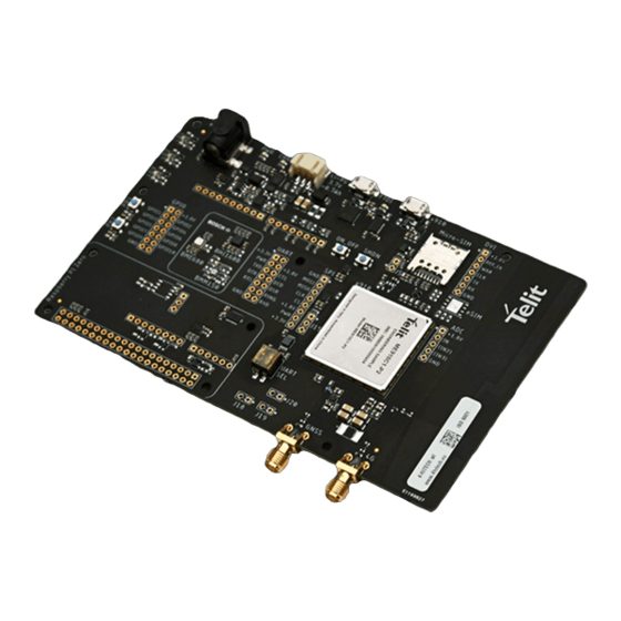
UNPACKING AND PREPARING THE BRAVO BOARD Bravo Board Content This Quick Start guide will walk you through the steps required to setup and run the Bravo EVK Board. Your Bravo kit contains the following: 1 Bravo EVK Board featuring Telit ME910C1-P2 IoT OneEdge-enabled module... - Page 10 For Arduino, male Berg connectors must be mounted on the bottom side of the board, as shown below: 2) For Raspberry Pi, female Berg connectors must be installed as shown below.: 1VV0301650 Rev. 0 Page 10 of 28 2020-03-18...
-
Page 11: Pc Usb Drivers Installation
3) For Raspberry Pi Zero, it is required to mount the female Berg connector on the top side. It is suggested to mount two 11mm teflon spacers between Bravo and the open hardware boards, such as (in example) Wurth PN... -
Page 12: Sim Card
SIM Card In order to allow the module to register and exchange data on a mobile network, insert a data-capable SIM card in the SIM holder on the Bravo board. The format supported is Micro-SIM. Please make sure the subscription supports data traffic on LPWA (either Cat-M or NBIoT) or GSM/GPRS radio access technologies. -
Page 13: Connecting The Board To A Pc
CONNECTING THE BOARD TO A PC Connecting Bravo to a PC is suggested to test board communication and familiarize with module AT commands. USB connection between Bravo and PC • Connect the micro-USB cable between the x910 port on the Bravo Board and the USB port of your PC or laptop. -
Page 14: Switching On The Telit Module
or Battery connector: Switching On the Telit Module After connecting the USB cable to the USB x910 port and optionally the power adapter to the power Jack or the battery to the Li-Po connector, the board is powered but the ME910 is still turned off. -
Page 15: Communication Ports
An alternate procedure is to go to Control Panel ► Network and Sharing Center ► change Adapter settings ► right-click on Cellular connection and disable it. • On Linux, configure ModemManager to exclude the devices from use as modems inserting the ID in ModemManager configuration files Communication Ports Two of the three USB devices can be used as terminals for sending AT commands to the MCU. - Page 16 To use FTDI ports, check “Ports (COM & LPT)” group: there will be a USB Serial Port (COM X) entry. This port will allow to communicate over the Main UART COM Port of ME910 MCU. 1VV0301650 Rev. 0 Page 16 of 28 2020-03-18...
-
Page 17: Telit At Controller Installation
Telit AT controller is a terminal application designed to send AT commands to Telit IoT modules. It can be downloaded for free at the following address: selecting “Telit AT Controller” https://www.telit.com/bravo/ Unzip the folder and run Setup_TATC_x.x.xx_XFP_x.x.x.msi file. Upon successful installation, the following files will be created on your desktop: Telit At Controller.lnk... - Page 18 Upon configuration, click Connect button: Module information such as IMEI, Manufacturer name, Model number and FW release version will be displayed: 1VV0301650 Rev. 0 Page 18 of 28 2020-03-18...
- Page 19 Click on AT Terminal to start the AT Terminal window: Issue the following AT commands to verify firmware version and options • AT#SWPKGV • AT#SWOPTIONS 1VV0301650 Rev. 0 Page 19 of 28 2020-03-18...
- Page 20 1VV0301650 Rev. 0 Page 20 of 28 2020-03-18...
-
Page 21: Use Cases
USE CASES The following use cases are for example only and show command sequences. Each command is documented in the Telit ME910 AT Commands manual: users are encouraged to consult it for further details. Module Registration, Data Connection to a Test Server The following example shows a simple AT command sequence to perform the following actions: •... - Page 22 Activate the PDP context with: AT#SGACT=1,1 And connect to the server using the socket dial command (in ONLINE MODE) AT#SD=1,0,10510,”modules.telit.com” 1VV0301650 Rev. 0 Page 22 of 28 2020-03-18...
- Page 23 Type “hello” (without quotes) in the input field an press Enter. The server will reply with an echo message: To exit ONLINE mode, type +++ and press Enter: Check socket status and exchanged data with AT#SS=1 AT#SI=1 1VV0301650 Rev. 0 Page 23 of 28 2020-03-18...
- Page 24 Close the socket and disable the PDP context with the following commands: AT#SH=1 AT#SGACT=1,0 1VV0301650 Rev. 0 Page 24 of 28 2020-03-18...
-
Page 25: Switch On Led At Startup
It is advisable to automatically turn on at least one LED at MCU wakeup: this is useful as visible feedback to know whether the IOT Module is powered ON or OFF. The BRAVO Board is equipped with 3 LEDs (connected to GPIO 1, 9 and 10) that can be enabled/disabled using the following AT commands: To turn ON the leds: •... -
Page 26: Glossary And Acronyms
GLOSSARY AND ACRONYMS Description TTSC Telit Technical Support Centre Universal Serial Bus High Speed Data Terminal Equipment UMTS Universal Mobile Telecommunication System WCDMA Wideband Code Division Multiple Access HSDPA High Speed Downlink Packet Access HSUPA High Speed Uplink Packet Access UART Universal Asynchronous Receiver Transmitter HSIC... -
Page 27: Document History
DOCUMENT HISTORY Revision Date Changes 2020-03-18 Initial Revision 1VV0301650 Rev. 0 Page 27 of 28 2020-03-18... - Page 28 Mod. 0809 2017-01 Rev.8...
Need help?
Do you have a question about the Bravo and is the answer not in the manual?
Questions and answers