Table of Contents
Advertisement
Quick Links
Advertisement
Table of Contents

Related Manuals for Telit Wireless Solutions CHARLIE


Summary of Contents for Telit Wireless Solutions CHARLIE
- Page 1 CHARLIE EVK HW User Guide 1VV0301670 Rev. 2 – 2020-10-29 Mod. 0805 2017-01 Rev.6...
-
Page 2: Notice
CHARLIE HW User Guide SPECIFICATIONS ARE SUBJECT TO CHANGE WITHOUT NOTICE NOTICE While reasonable efforts have been made to assure the accuracy of this document, Telit assumes no liability resulting from any inaccuracies or omissions in this document, or from use of the information obtained herein. -
Page 3: Usage And Disclosure Restrictions
CHARLIE HW User Guide USAGE AND DISCLOSURE RESTRICTIONS License Agreements The software described in this document is the property of Telit and its licensors. It is furnished by express license agreement only and may be used only in accordance with the terms of such an agreement. -
Page 4: Applicability Table
CHARLIE HW User Guide APPLICABILITY TABLE PRODUCTS CHARLIE EVALUATION KIT 1VV0301670 Rev. 2 Page 4 of 37 2020-10-29... -
Page 5: Table Of Contents
CHARLIE HW User Guide Contents NOTICE COPYRIGHTS ....................2 COMPUTER SOFTWARE COPYRIGHTS ............2 USAGE AND DISCLOSURE RESTRICTIONS ..........3 License Agreements ............... 3 Copyrighted Materials ..............3 III. High Risk Materials ................ 3 Trademarks ..................3 Third Party Rights ................3 APPLICABILITY TABLE .................. - Page 6 CHARLIE HW User Guide 4.5. MCU Reset Button ............... 24 4.6. Battery Charger ................25 4.7. 3V3 Power Supply ................ 28 4.8. 1V8 Power Supply ................ 29 4.9. 3V8 Power Supply ................ 30 4.10. ME310 ON/OFF Switch ..............31 4.11.
-
Page 7: Introduction
CHARLIE HW User Guide INTRODUCTION 1.1. Scope Scope of this document is to describe the hardware components of the CHARLIE EVK board based on Telit ME310G1-WW module and ATSAMD21G18 MCU from Microchip. 1.2. Audience This document is intended for Telit customers, who are integrators, about to implement their applications using our CHARLIE EVK board. -
Page 8: Text Conventions
CHARLIE HW User Guide 1.4. Text Conventions Danger – This information MUST be followed or catastrophic equipment failure or bodily injury may occur. Caution or Warning – Alerts the user to important points about integrating the module, if these points are not followed, the module and end user equipment may fail or malfunction. -
Page 9: Related Documents
CHARLIE HW User Guide 1.5. Related Documents • ME310G1 HW User Guide, 1VV0301351 1VV0301670 Rev. 2 Page 9 of 37 2020-10-29... -
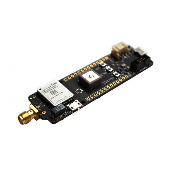
Page 10: Overview
CHARLIE HW User Guide OVERVIEW The aim of this document is to describe the “CHARLIE” EVK board based on Telit ME310G1-WW modem module and ATSAMD21G18 MCU from Microchip. The CHARLIE board is an Arduino MKR form factor evaluation board that can be programmed with Arduino IDE or with native tools for ATSAMD21 from Microchip. - Page 11 CHARLIE HW User Guide Figure 2 - CHARLIE Block Diagram The CHARLIE EVK has 2 USB connectors: • The first USB connector is located at opposite site of ME310 module and SMA connector is connected to the ATSAMD21 microcontroller •...
-
Page 12: Notice
CHARLIE HW User Guide NOTICE While reasonable efforts have been made to assure the accuracy of this document, Telit assumes no liability resulting from any inaccuracies or omissions in this document, or from use of the information obtained herein. The information presented in this document is believed to be accurate and reliable. -
Page 13: Connectors
CHARLIE HW User Guide CONNECTORS 3.1. Arduino MKR format Pin-out Figure 3 - Arduino MKR Pinout Signal Function Type MCU I/O POWER SUPPLY J4,14 5.0 V I/O Level J4,13 External Power Input J4,12 +3V3 3.3 V I/O Level J4,11 GPIO INTERFACE @ 3V3... - Page 14 CHARLIE HW User Guide J4,6 GPIO/I2C SDA PA08 J4,5 GPIO/SPI MISO PA19 J4,4 GPIO/SPI SCK PA17 J4,3 GPIO/SPI MOSI PA16 J4,2 GPIO/PWM PA21 J4,1 GPIO/PWM PA20 J3,14 GPIO/PWM PB11 J3,13 GPIO/PWM PB10 J3,12 GPIO/PWM PA11 J3,11 GPIO/PWM PA10 J3,10 GPIO...
-
Page 15: Mcu Native Usb Connector
CHARLIE HW User Guide 3.2. MCU Native USB Connector Figure 4 – ATSAMD21 Native USB Signal Function Type Comment POWER SUPPLY J1,1 J1,5 USB HS 2.0 COMMUNICATION PORT (FW upgrade and Data) J1,2 USB_DM USB differential Data (-) PA24 J1,3... -
Page 16: Me310 Native Usb Connector
CHARLIE HW User Guide 3.3. ME310 Native USB Connector Figure 5 – ME310 Native USB Signal Function Type ME310 POWER SUPPLY J7,1 USB_VBUS J7,5 USB HS 2.0 COMMUNICATION PORT (FW upgrade and Data) J7,2 USB_DM USB differential Data (-) J7,3... -
Page 17: Mcu Debug Connector
CHARLIE HW User Guide 3.4. MCU DEBUG connector Figure 6 - DEBUG connector Signal Function Type Comment POWER SUPPLY J2,1 J2,3 J2,5 J2,9 DEBUG Interface J2,2 SWDIO DEBUG DATA PA31 J2,4 SWCLK DEBUG CLOCK PA30 J2,10 RESETN RESET RESETN 1VV0301670 Rev. 2... -
Page 18: Sim Connectors
CHARLIE HW User Guide 3.5. SIM Connectors Figure 7 - SIM Sockets The board supports a micro SIM socket and includes pads to solder an eSIM: both inputs are ESD protected. 1VV0301670 Rev. 2 Page 18 of 37 2020-10-29... -
Page 19: Antenna Connectors
CHARLIE HW User Guide 3.6. ANTENNA Connectors Figure 8 – Antennas The 4G Cellular antenna signal is connected to the J8 SMA connector. The GNSS Signal can be connected either to the uFL connector J9 or the GPS Patch Antenna, which is enabled by default. -
Page 20: Circuit Blocks
CHARLIE HW User Guide CIRCUIT BLOCKS 4.1. MCU to ME310 serial connection Figure 9 –MCU to ME310 Serial Connection The ATSAMD21 MCU GPIO works at 3.3 V while the ME310 GPIO levels are 1.8 V. To connect the two devices using a serial connection with hardware handshake, level shifters are used. -
Page 21: Bma400 Accelerometer
CHARLIE HW User Guide 4.2. BMA400 Accelerometer Figure 10 – BMA400 Accelerometer The CHARLIE board mounts a Bosch Sensortech BMA400 ultra low power acceleration sensor, connected to the ATSAMD21 MCU through I2C communication. Direction Function PA09 I2C Clock PA08 I2C Data... -
Page 22: Mcu Buttons And Leds
MCU Buttons and LEDs Figure 11 – ATSAMD21 Pushbuttons and Leds The CHARLIE board has a user-available LED, LD1 and a button, PB2 connected to ATSAMD21 MCU. The led is ON when the MCU pin is high, while the button is active LOW. -
Page 23: Me310 Sled
CHARLIE HW User Guide 4.4. ME310 SLED Figure 12 – ME310 SLed The CHARLIE board has a LED, LD2 connected to ME310 S_LED pin. The led is ON when the MCU pin is high. Direction Function Amber LD2/S_LED 1VV0301670 Rev. 2... -
Page 24: Mcu Reset Button
CHARLIE HW User Guide 4.5. MCU Reset Button Figure 13 – RESET button The CHARLIE board has one RESET button PB1 connected to ATSAMD21 MCU. 1VV0301670 Rev. 2 Page 24 of 37 2020-10-29... -
Page 25: Battery Charger
Battery Charger Figure 14 - Battery Charger A +3.7 V Lipo battery (not included) connected to J10 can power the CHARLIE board. The battery can be charged by the onboard charger, which receives receives +5V from the VIN connector, MCU USB Native Connector or ME310 Native USB connector. - Page 26 Figure 16 Connector without temperature sensor (top) and with temperature sensor (bottom) By default, the Charlie board is configured for batteries without NTC temperature sensor. To disable battery temperature monitoring, the 10 Kohm resistor R31 is mounted. If a battery with NTC temperature sensor is connected to the board WITHOUT removing R31 resistor, the battery charger will not function.
- Page 27 CHARLIE HW User Guide WARNING Use Li-Ion battery V = 3.7V, V = 4.2V Capacity >= 700 mAh chrg Li-Po batteries are charged at 4.2V with a current that is usually half the nominal capacity (C/2). This board has a dedicated IC that has a preset charging current of 350mAh: this means that the MINIMUM capacity of the Li-Po battery shall be 700 mAh.
-
Page 28: 3V3 Power Supply
CHARLIE HW User Guide 4.7. 3V3 Power Supply Figure 17 - 3V3 Power Supply The CHARLIE board provides a +3.3 V power source to power: • ATSAMD21 MCU and LEDs • BMA400 Accelerometer • Level Shifters 1VV0301670 Rev. 2 Page 28 of 37... -
Page 29: 1V8 Power Supply
CHARLIE HW User Guide 4.8. 1V8 Power Supply Figure 18 – ME310 internal power supply The ME310 module is powered at 3.8 V, but all I/O pins operate at 1.8 V: the LDO provides 1.8 V level to: • level translators •... -
Page 30: 3V8 Power Supply
CHARLIE HW User Guide 4.9. 3V8 Power Supply Figure 19 – ME310 3.8 V power supply The ME310 module is powered at 3.8V, the Buck converter provides 3.8V power supply for: • ME310 Module • NCP612S LDO regulator for uFL GPS antenna 1VV0301670 Rev. -
Page 31: Me310 On/Off Switch
CHARLIE HW User Guide 4.10. ME310 ON/OFF Switch Figure 20 - ON/OFF Switch Circuit The ON_OFF pin can be controlled by the PB3 bush-button or by the 310_ON_OFF signal that is connected to PB08 output pin of ATSAMD21 MCU. 4.11. -
Page 32: Mechanical Design
CHARLIE HW User Guide MECHANICAL DESIGN 5.1. Drawing 1VV0301670 Rev. 2 Page 32 of 37 2020-10-29... -
Page 33: Safety Recommendations
CHARLIE HW User Guide SAFETY RECOMMENDATIONS 6.1. READ CAREFULLY Be sure the use of this product is allowed in the country and in the environment required. The use of this product may be dangerous and has to be avoided in the following areas: •... -
Page 34: Acronyms
CHARLIE HW User Guide ACRONYMS Telit Technical Support Centre TTSC Universal Serial Bus High Speed Data Terminal Equipment Universal Mobile Telecommunication System UMTS Wideband Code Division Multiple Access WCDMA High Speed Downlink Packet Access HSDPA High Speed Uplink Packet Access... - Page 35 CHARLIE HW User Guide Chip Select Real Time Clock Printed Circuit Board Equivalent Series Resistance Voltage Standing Wave Radio VSWR Vector Network Analyzer 1VV0301670 Rev. 2 Page 35 of 37 2020-10-29...
-
Page 36: Document History
CHARLIE HW User Guide DOCUMENT HISTORY Revision Date Changes 2020-07-20 Initial revision 2020-09-02 Battery information added 2020-10-29 ME310 variant updated to ME310G1-WW 1VV0301670 Rev. 2 Page 36 of 37 2020-10-29... - Page 37 Mod. 0805 2017-01 Rev.6...
Need help?
Do you have a question about the CHARLIE and is the answer not in the manual?
Questions and answers