
Related Manuals for Infineon TLF4277 Demoboard


Summary of Contents for Infineon TLF4277 Demoboard
- Page 1 T L F 4 2 7 7 D e m o b o a r d A p p l i c a t i o n N o t e R e v . 1 . 1 , 2 0 1 2 - 0 4 - 2 5 A u t o m o t i v e P o w e r...
-
Page 2: General Description
Introduction Introduction The TLF4277 Demoboard is a demonstration of the Infineon low drop out linear voltage regulator with integrated current monitor. The TLF4277 is the ideal companion IC to supply active antennas for car infotainment applications. The adjustable output voltage makes the TLF4277 capable of supplying the majority of standard active antennas. -
Page 3: Technical Specification
TLF4277 Demoboard Technical Specification Technical Specification The chapter provides a brief technical description of TLF4277. Adjustable Output Voltage The output voltage of the TLF4277 can be adjusted between 5 V and 12 V by an external output voltage divider, closing the control loop to the voltage adjust pin ADJ. - Page 4 Current and Protection Monitor Functions The TLF4277 Demoboard provides a set of advanced monitor functionality. The current flowing into the power stage can be monitored at the CSO output. In addition the current limitation can be adjusted via external resistors.
- Page 5 TLF4277 Demoboard Technical Specification Short Circuit to V 3.1 V typical 2,95 Thermal Shut Down 2.80 V typical 2,65 Current limitation and SC to GND 2.55 V typical 2,45 Linear Current Sense Band up to 2.45 V 163 170 [mA]...
- Page 6 TLF4277 Demoboard Technical Specification 2.2.2 Adjustable Output Current Limitation The TLF4277 has an adjustable current limitation for the current flowing into the power stage (pin CS2). If the level of the voltage drop across the sense resisto is higher than the desired linear monitor range the output SHUNT current of the TLF4277 will be limited.
-
Page 7: Operating Conditions
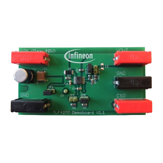
TLF4277 Demoboard Demoboard Demoboard The TLF4277 Demoboard is equipped with TLF4277 and the necessary external components. Figure 5 TLF4277 Demoboard V1.1 Operating Conditions To avoid damage of the Demoboard, the maximum of the operating range defined in Table 1 must be followed. -
Page 8: Board Configuration
• Enable function. 3.3.1 Output Voltage Setting The TLF4277 Demoboard provides two output voltage options 5 V and 8 V, which can be configured by setting the jumpers JP2 and JP3 (see Figure Table 2 Jumper setting for output voltage... -
Page 9: Typical Performance
TLF4277 Demoboard Demoboard Typical Performance In this chapter, the typical performance of the current and protection monitor functions are shown with lab measurement results. All measurements are done on TLF4277 Demoboard under the following condition: • = 25°C ambient •... - Page 10 TLF4277 Demoboard Demoboard Setup 2: 5 V output voltage (JP2 close, JP3 open) 54 mA current limitation (JP4 close, JP5 open) The typical current monitor performance is shown in Figure 7. The current sense accuracy is specified in section 7.2 on page 17 of the TLF4277 data sheet [1].
-
Page 11: Thermal Shutdown
TLF4277 data sheet [1]. Table 8 CSO output voltage during overvoltage Value in data sheet (Typ.) Measured typical value 3.1 V 3.115 V Schematic Figure 8 TLF4277 Demoboard V1.1 schematic Application Note Rev. 1.1, 2012-04-25... -
Page 12: Bill Of Material
TLF4277 Demoboard Demoboard Bill of Material Table 9 Bill of material Part Value Package Banana jack BABU4MM Banana jack BABU4MM Banana jack BABU4MM Banana jack BABU4MM Banana jack BABU4MM 10u/50V C2220K 100u/50V CPOL-EUE 10u/16V not mounted C1206 2u2/10V C0805 10u/16V... -
Page 13: Board Layout
TLF4277 Demoboard Demoboard Board Layout Figure 9 TLF4277 Demoboard V1.1 top layer component placement Figure 10 TLF4277 Demoboard V1.1 top layer Application Note Rev. 1.1, 2012-04-25... - Page 14 TLF4277 Demoboard Demoboard Figure 11 TLF4277 Demoboard V1.1 bottom layer Application Note Rev. 1.1, 2012-04-25...
- Page 15 This Demoboard is offering limited features allowing you only to evaluate and test the Infineon products. The Demoboard is not an end product (or finished appliance), nor is it intended or authorized by Infineon to be integrated into end products. You are not authorized to use the Demoboard in any production system.
- Page 16 TLF4277 Demoboard Reference Reference TLF4277 Data Sheet Application Note Rev. 1.1, 2012-04-25...
-
Page 17: Revision History
TLF4277 Demoboard Revision History Revision History TLF4277 Demoboard Revision History: Rev. 1.1, 2012-04-25 Previous Version(s): Rev. 1.0, 2012-03-12 Page Subjects (major changes since last revision) Restrictions disclaimer added. Application Note Rev. 1.1, 2012-04-25... - Page 18 Infineon Technologies components may be used in life-support devices or systems only with the express written approval of Infineon Technologies, if a failure of such components can reasonably be expected to cause the failure of that life-support device or system or to affect the safety or effectiveness of that device or system. Life support devices or systems are intended to be implanted in the human body or to support and/or maintain and sustain and/or protect human life.
Need help?
Do you have a question about the TLF4277 Demoboard and is the answer not in the manual?
Questions and answers